Servo-Controlled Robotic Hand Drill
by Andrija Dean in Circuits > Arduino
1480 Views, 11 Favorites, 0 Comments
Servo-Controlled Robotic Hand Drill


I am an engineering student from Croatia, and my school recently bought a robotic hand for teaching purposes. When I saw it, I was inspired to make my own version but didn't have a reason to do so. My dad told me about the Instructables webpage and its contests a long time ago, so one day I decided to see if there were any contests going on, and to my surprise, there was one that was a perfect fit for my project. The "Make It Move" contest encouraged me to finally create the hand I wanted. Without much procrastination, I started thinking and designing the robotic drill using my dad's old electronic parts. I will show you how I did it and haw you can crate your own version.
Supplies


The number of servo motors and potentiometers for the servo motors can be changed to your liking, just keep in mind that the code won't be exactly the same for more or fewer than three servo motors.
3D Prints


3D printing and modeling played a huge part in my project. I would say it turned my vision into reality, but unfortunately, sometimes I calculated the wrong dimensions and it didn't fit. However, in the end, everything fit perfectly. Here are 3D models of the parts i used:
Wiring


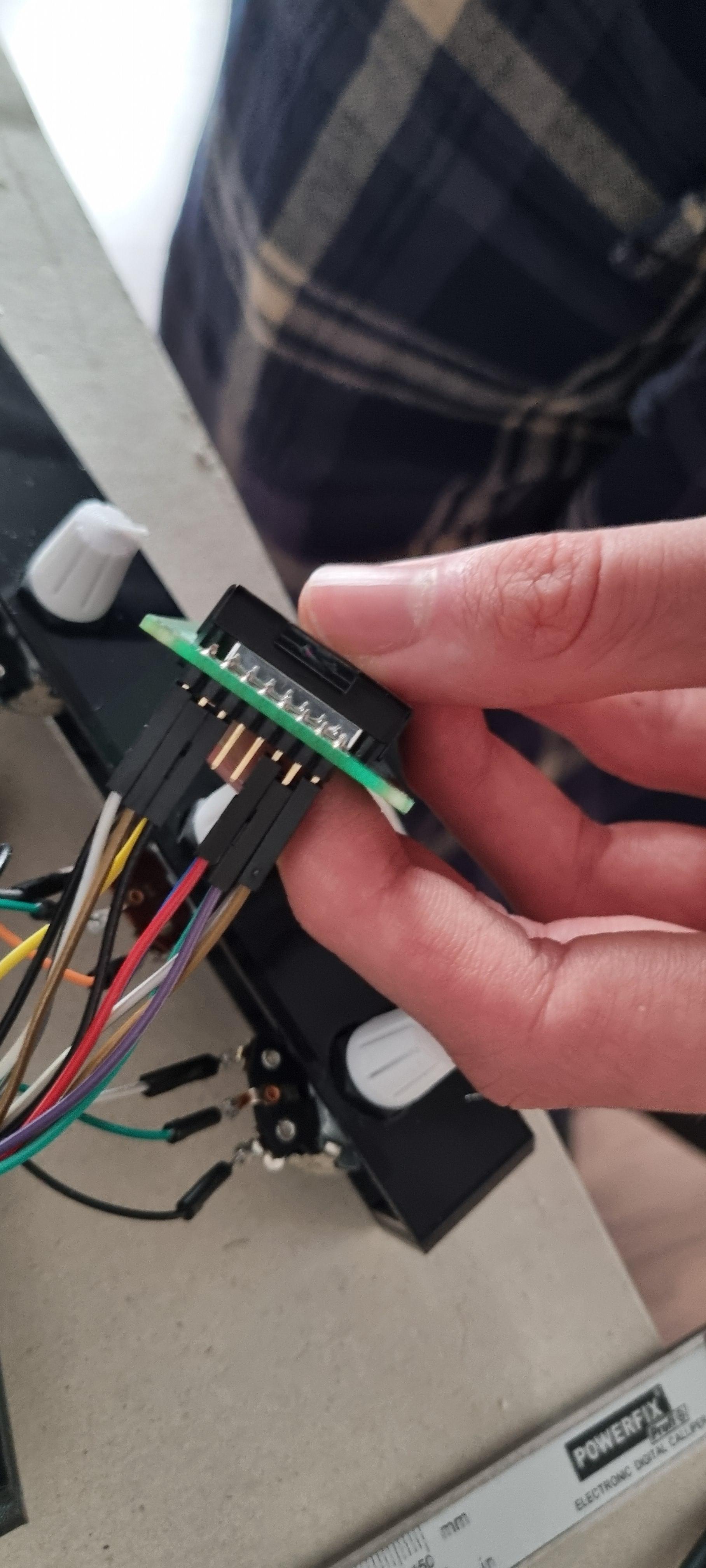
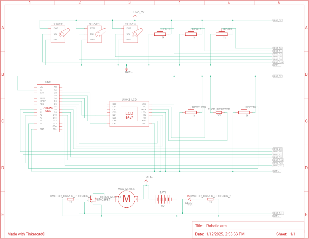
The first thing to do was connecting the wires. Connecting servo motors and a potentiometer to the Arduino was fairly simple, but connecting the Arduino with the LCD wasn't as easy because I couldn't find the datasheet for my LCD. To connect the Arduino with the LCD, I asked AI to help me, and after some trial and error, it finally worked. The last thing left to connect was the DC motor with the motor driver and, again, the Arduino. After a few searches, I found the datasheet for my motor driver and was able to connect everything with no problem.
Datasheet


Code

In this code, we are including two libraries: one for math functions and another for controlling the 16x2 LCD display. The next few lines initialize and declare constant variables for the motor, servo motors, and potentiometers. On the 12th line, there is an important constant variable, "servoNum," which represents the number of servo motors, so if you don't have three servos, don't forget to change that variable to the correct number of servos you have. Below that variable is a structure called ServoMotor, which declares the variables needed for controlling the servo motors. In the setup() function, we initialize these variables for each servo. There are a total of three functions used: controlling the servos, controlling the DC motor, and printing data on the LCD. In the loop() function, we read the analog input from the servo potentiometers and call the functions mentioned earlier.
Downloads
Have Fun


Even though this project is not pioneering, it is an example of how you can learn form any project that you do. This project had its ups and downs, but in the end, it all came together and inspired me to do something again, regardless of the contest result. I really hope this tutorial inspired you to do something you've always wanted to do but didn't have the courage to try.