Shaker Style Doll House Kitchen
by oliverb in Workshop > 3D Printing
102 Views, 0 Favorites, 0 Comments
Shaker Style Doll House Kitchen

This Instructable details how to build a 1/12th scale Doll House Shaker style kitchen with opening cabinet doors and LED downlights.
Traditionally Doll Houses were built in Victorian or Edwardian style. This kitchen was designed for my 1960s style Doll House which is fitted out in contempory English style.
Built from a mixture of wood and 3D printed parts that are bonded together. If required it would be very easy to 3D print the wooden parts as planks or even open boxes.
The Kitchen is "in frame" style and has 3D printed frame and doors while the cabinet carcasses, shelving and worktops are made from 3mm plywood.
LED kitchen downlights are fitted into the wall units.
I have designed a built in fridge freezer, microwave oven, conventional oven and touch sensitive electric hob to go with this kitchen. See the Doll House Kitchen appliances Instructable link below for details.
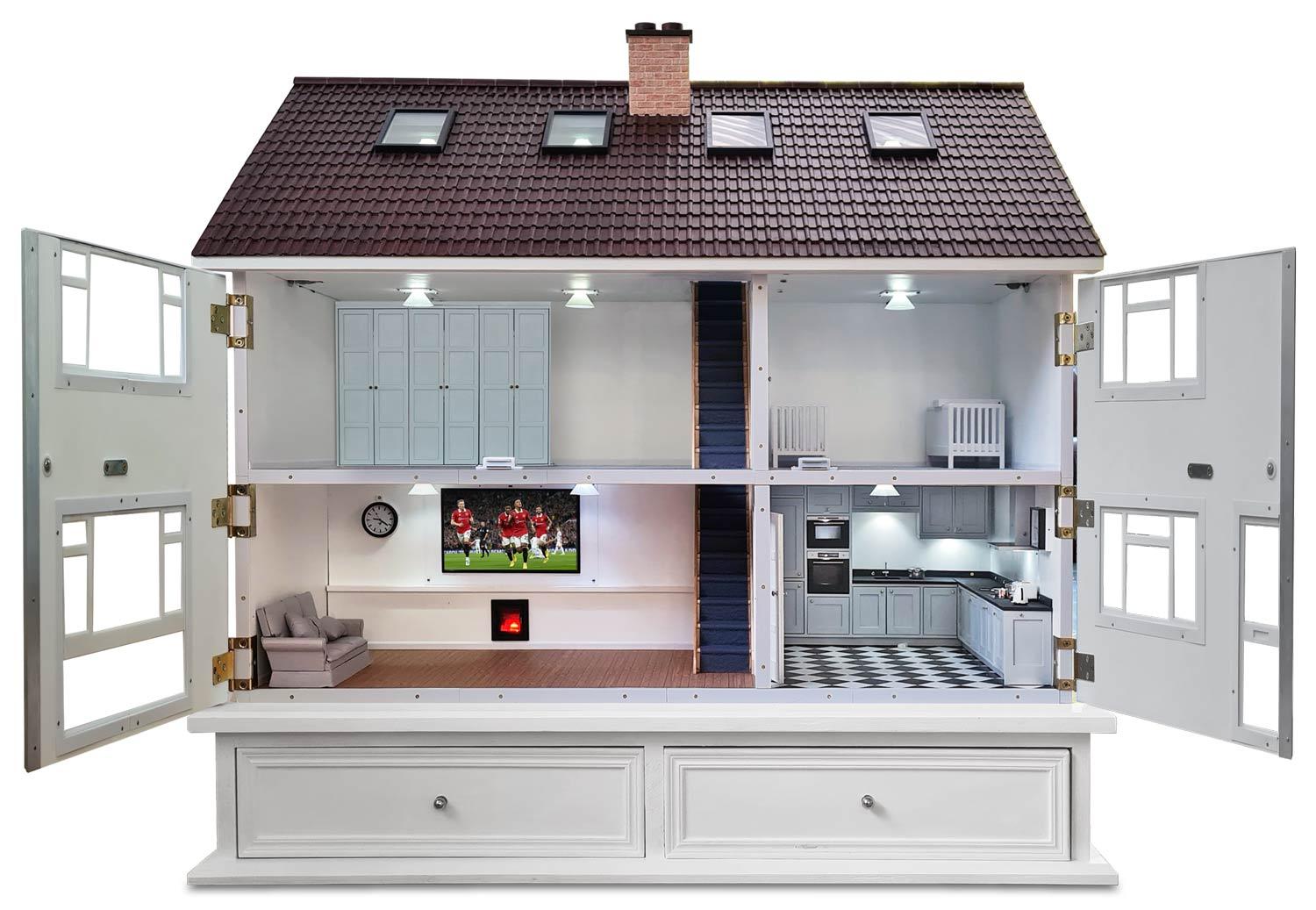
This Instructable is part of my 1960s Doll House build modelled on my own house and built for my granddaughter's 3rd birthday.
The whole build is so big I have split it into a number of seperate Instructables.
See 1960s Doll House build here.
See lighting Instructable here.
See Doll House Smart TV, Sound to light and Woodburner Instructable.
See Doll House Christmas Lights Instructable here.
Supplies
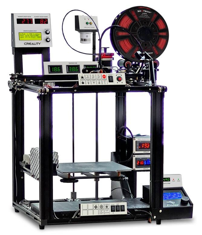
3D printer with 220mm x 220mm bed.
Wood working tools jigsaw, hand saw, files, drill and table saw. Power tools not essential.
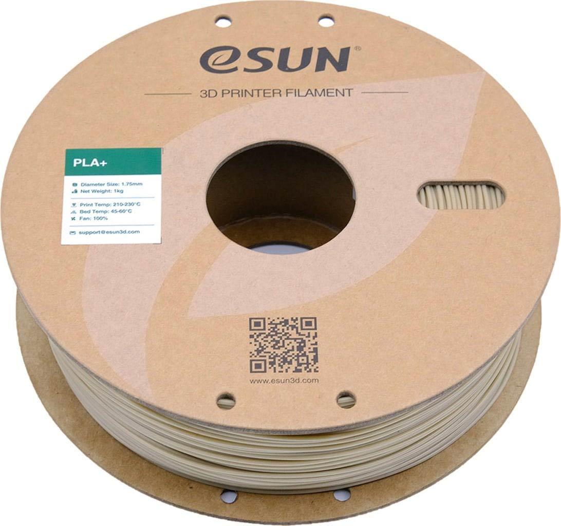
3D filament in white PLA/PLA+
3mm hardwood plywood (not required if you 3D print the wood parts)
Cyanoacrylate Glue (super glue)
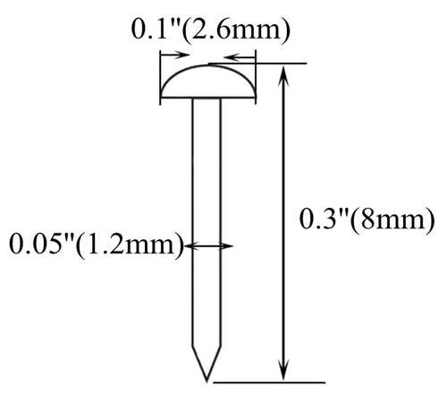
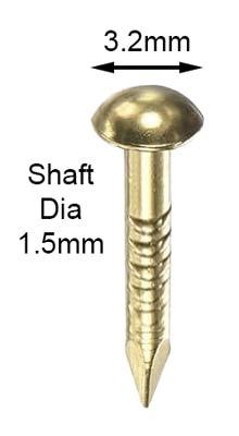
Door Knobs 2.6mm round headed brass nails
Appliance illumination LEDs https://amzn.eu/d/4nKblZ2
Resistors 180 Ohm https://amzn.eu/d/9vjeILD Qty 1 per LED
1mm wire for appliance hinges
M2 countersunk woodscres
Construction General
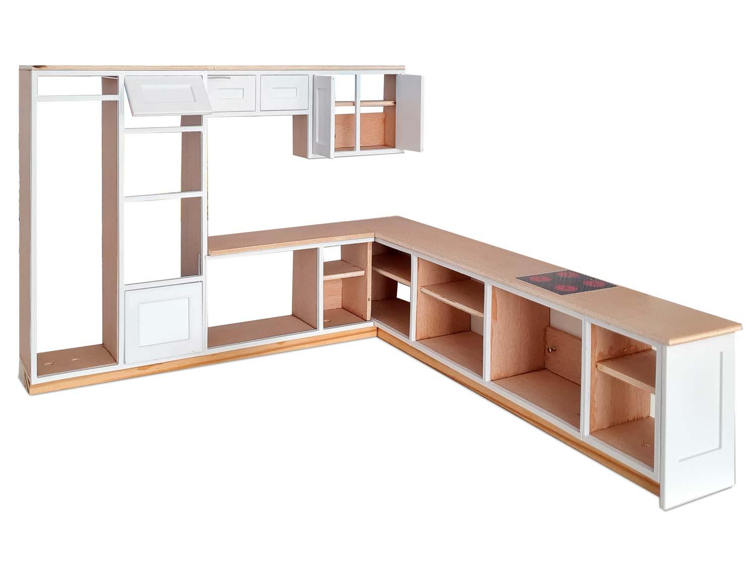


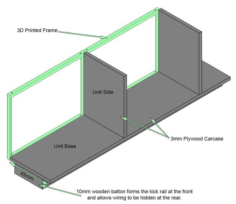
Pic 1. This images shows the basic construction of the kitchen units.
Worktops, unit carcasses and shelving are made from strips of 3mm plywood.
The pelmet on the larder and wall units is also 3mm plywood.
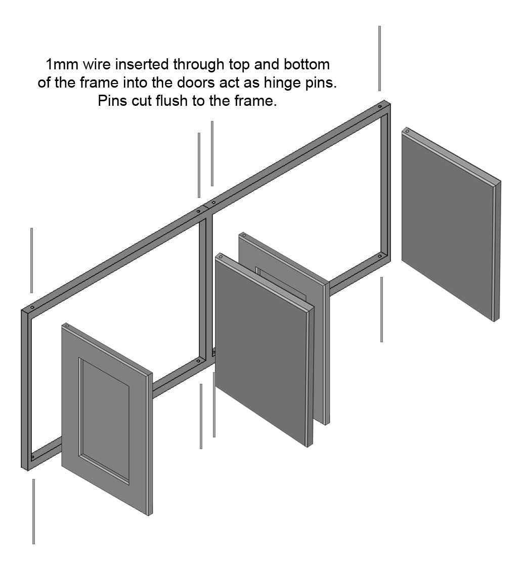
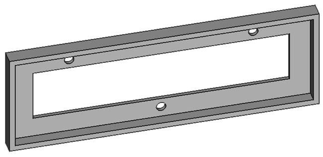
Pic 2. The kitchen unit external frames, doors and decorative end panel are 3D printed.
The doors open and close hinged on metal pins through the external frames.
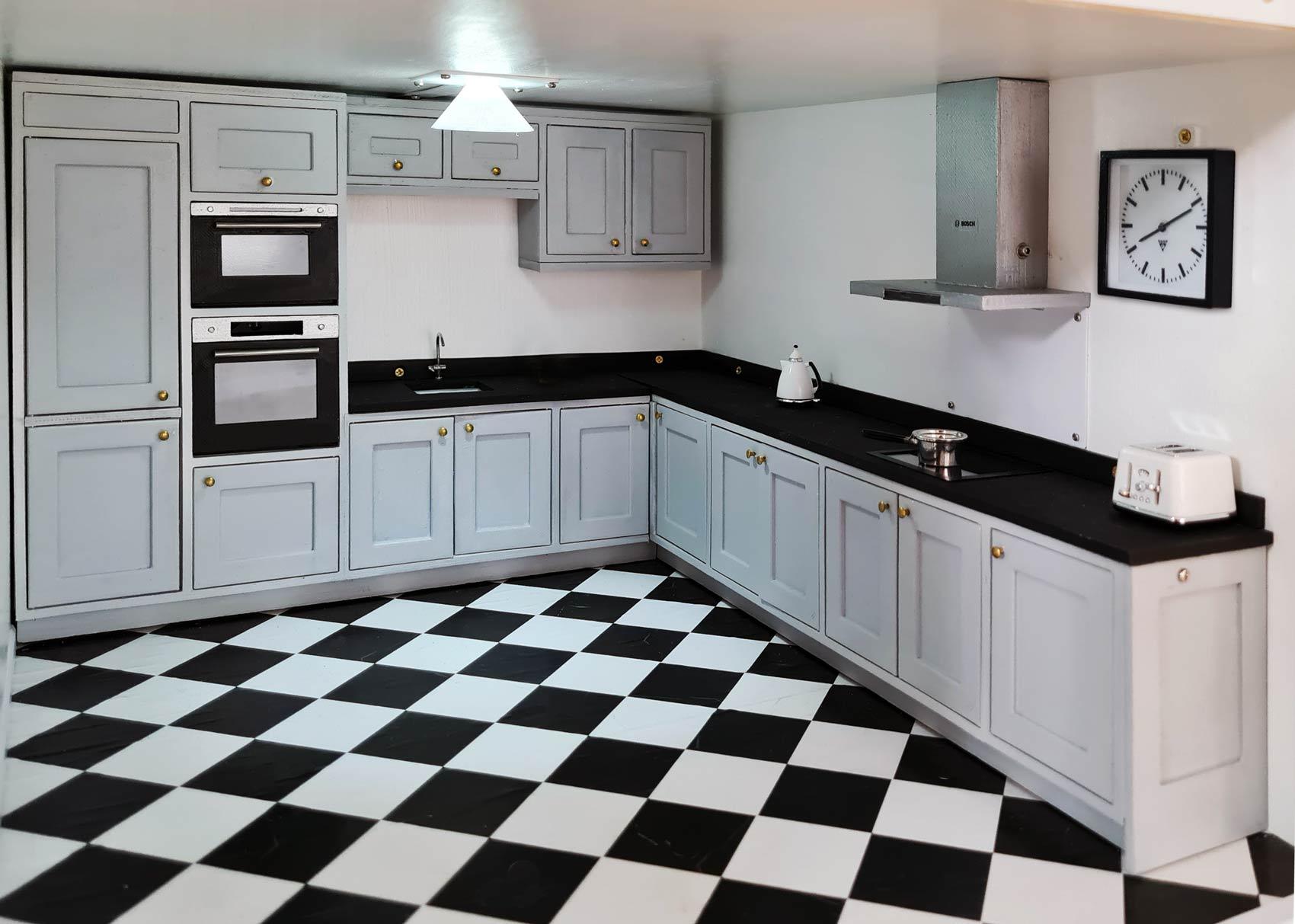
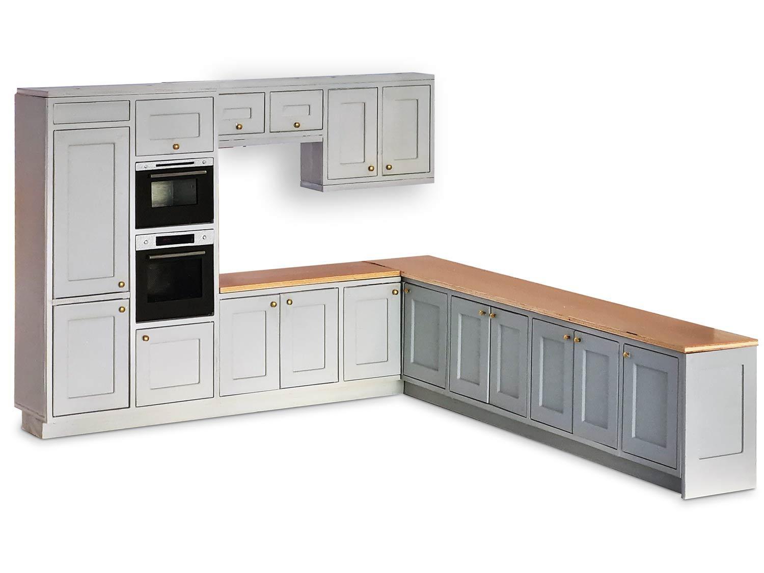
Pic 3. Completed kitchen units with 3mm plywood worktop waiting for cutouts for the sink and hob.
Pic 4. Completed kitchen with appliances installed. See Doll House Kitchen Appliances Instructable here.
3D Printed Frames

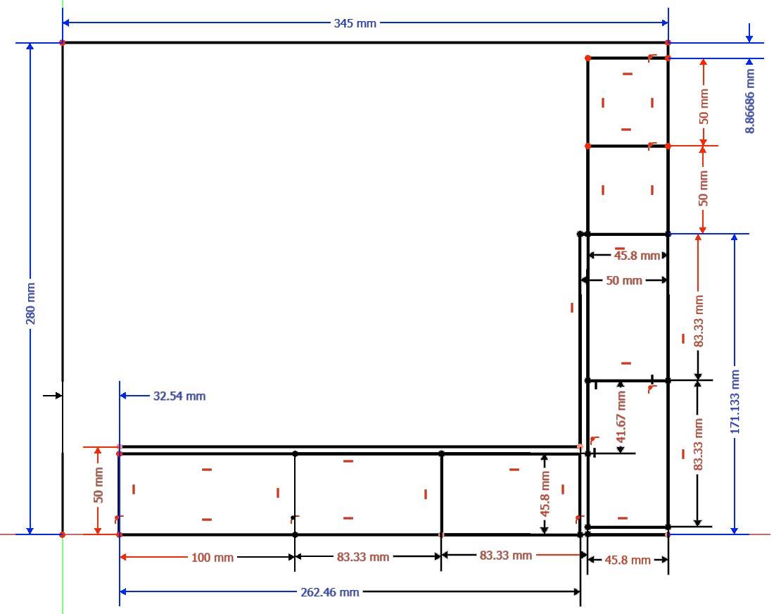
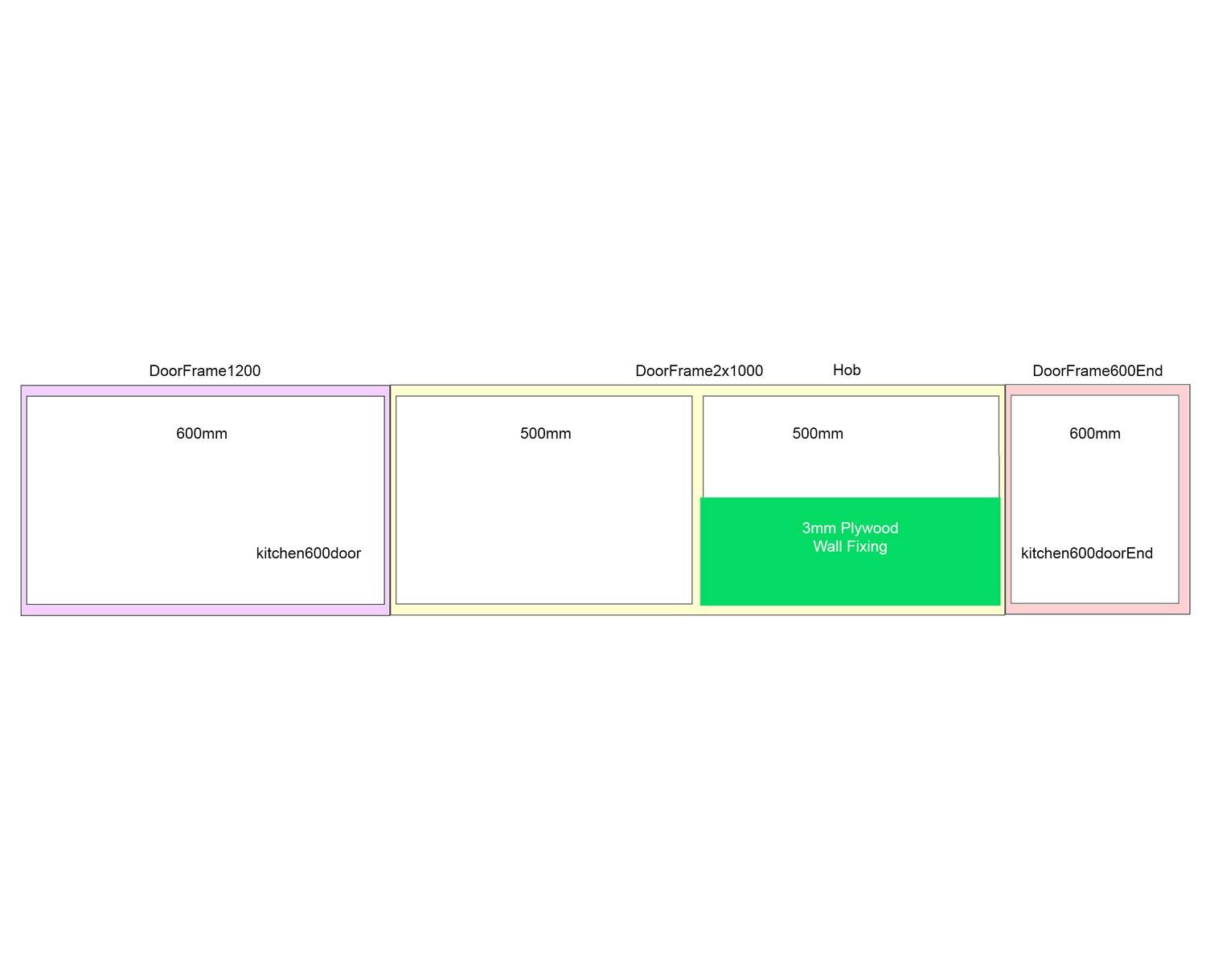
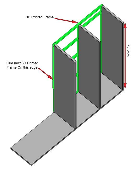
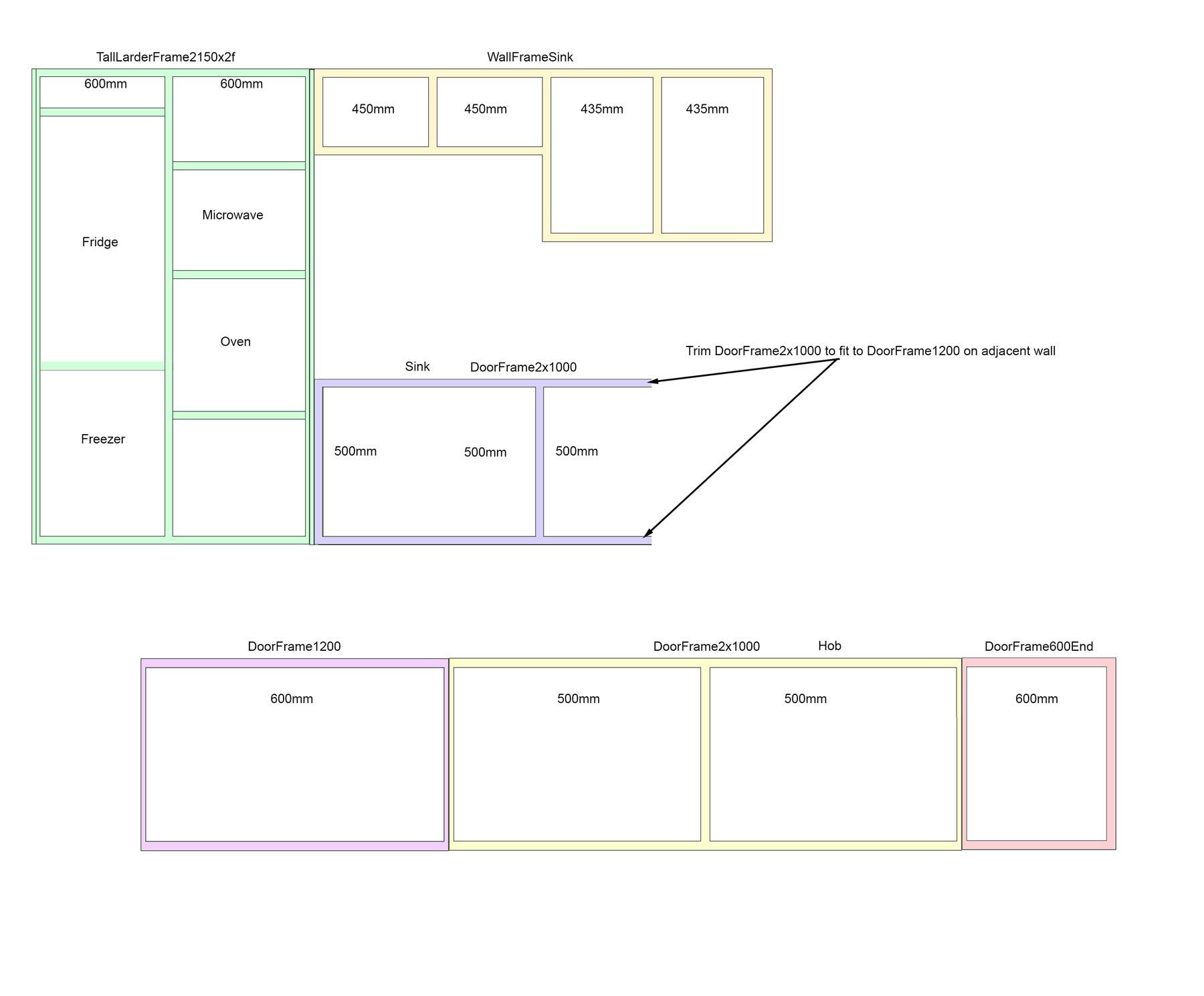
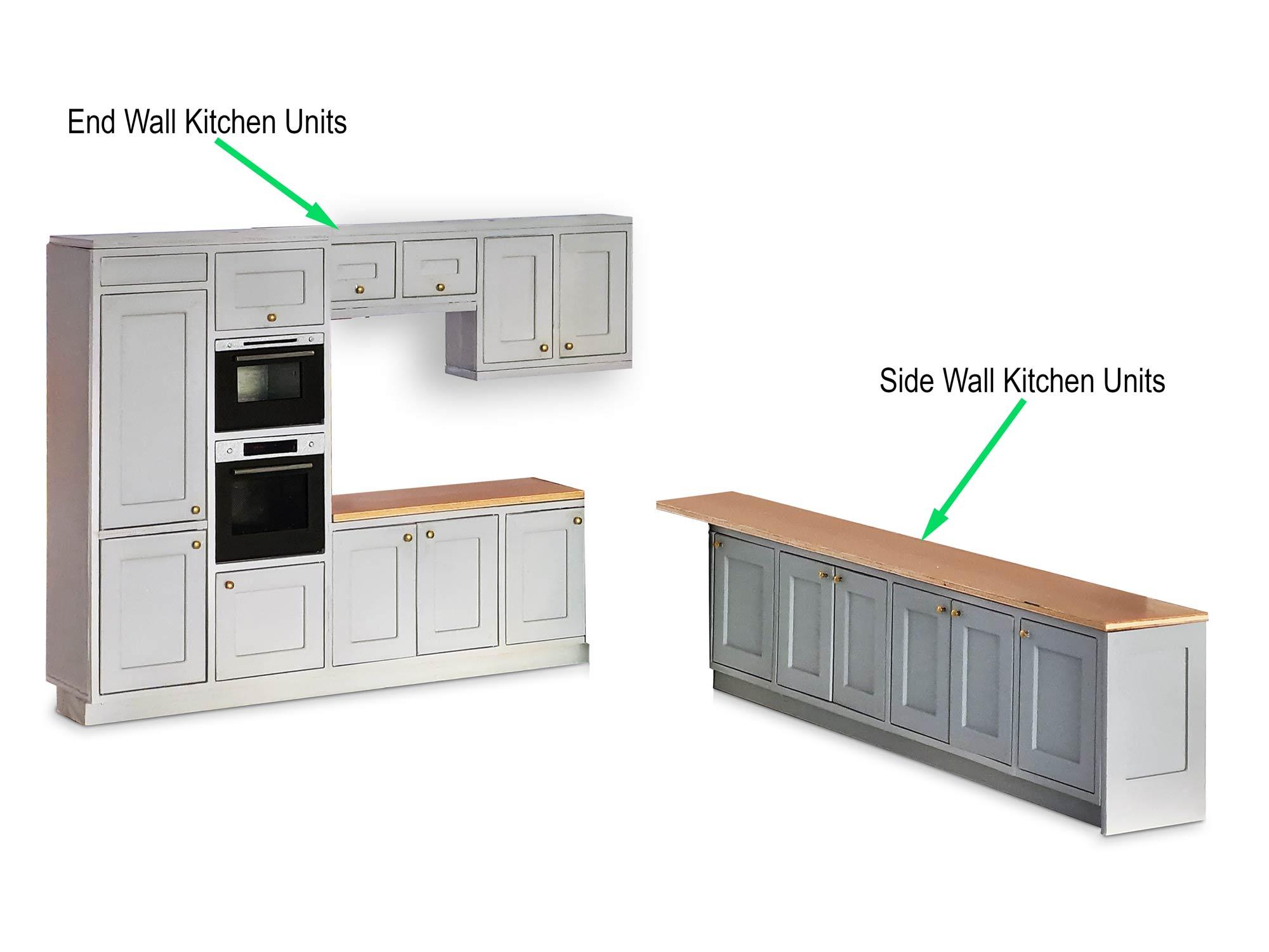
Pic 1. This shows the names and locations of the 3D printed frames.
The top image shows the end wall and the lower image the left side wall looking from the front of the house.
3D Print the frames from this list.
Note DoorFrame2x1000 on the end wall is cut down to fit into the corner.
Pic 2. Fixing detail showing how the doors, vertical & horizontal are fixed to the frames.
Pic 3. Kitchen plan showing floor units.
Side Wall Base Carcass Construction
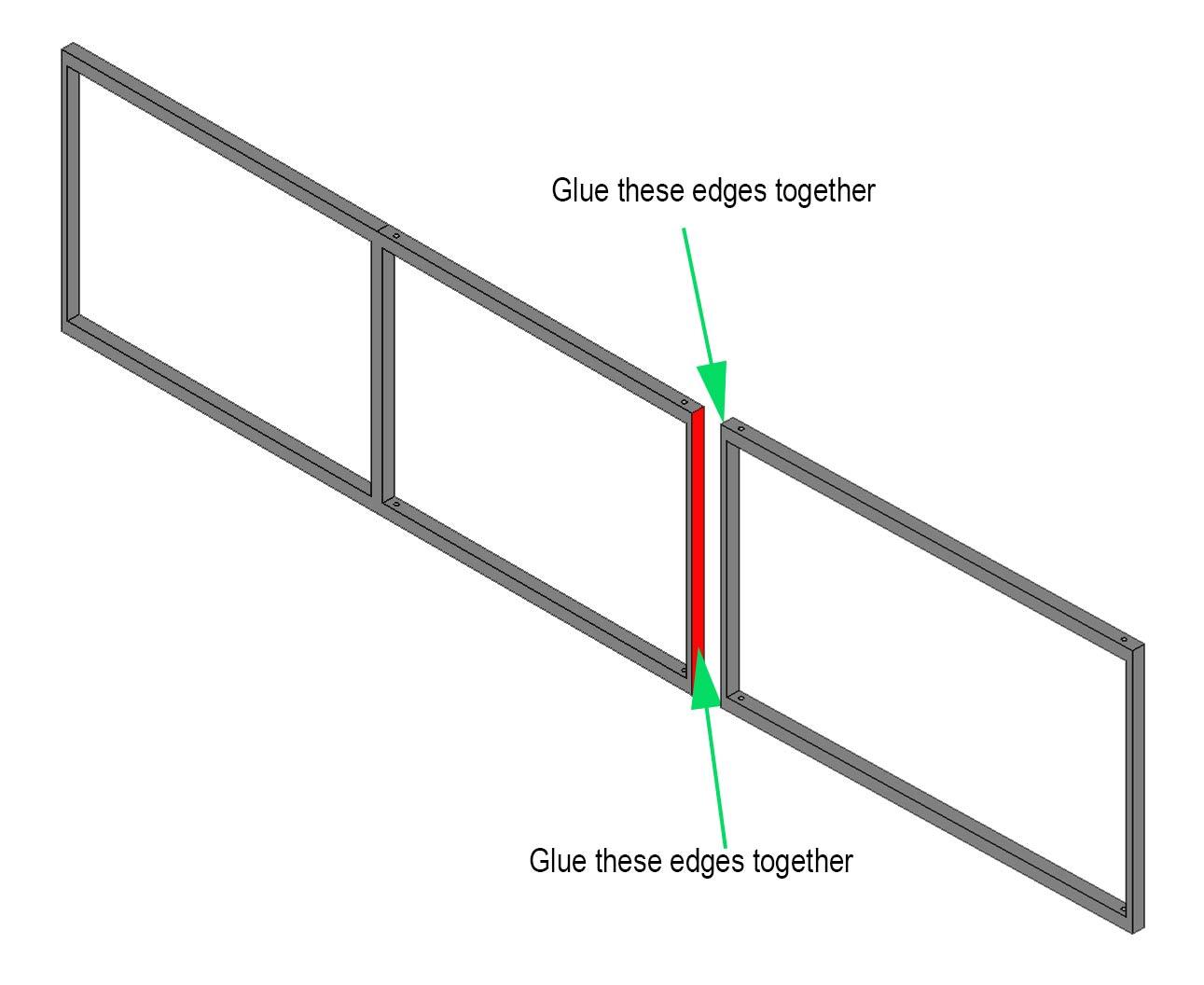

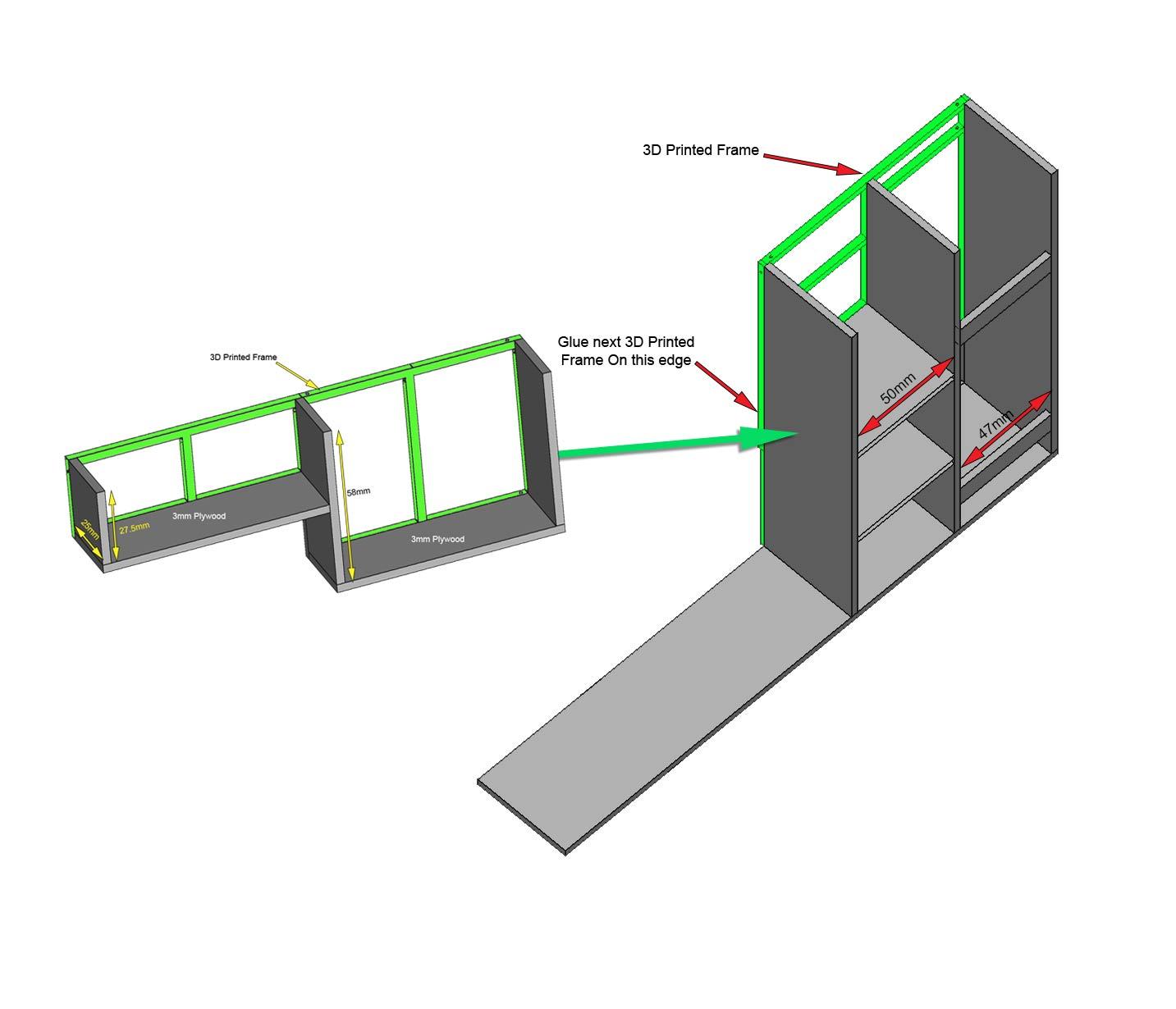
Pic 1. First the 3D the printed frames are glued together to form the complete run of units rear and side.
Do this on a flat surface with a timber guide to keep the rail aligned while the glue dries.
Pic 2. Is used as a referance for gluing.
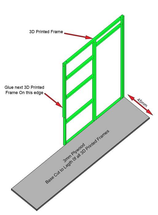
Pic 3. Next cut a 45mm wide strip of wood to the total length of the lower frame rail.
Glue this length that will form the cabinet base to the lower frame rail.
Now cut 45mm wide strips into 59.5mm lengths to form all the cabinet sides.
Glue the sides to the base plywood and 3D printed frame uprights.
Finally a 10mm high wooden baton is glued to the underside of the base.
This is set back from the front and rear of the base to form the kick rail at the front and wiring space at the rear.
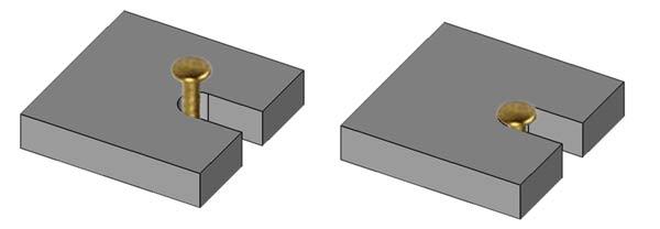
Pic 4. A 3mm Plywood length around 30mm high is fitted at the inside rear of the Hob unit carcass. This is used to fix the side units to the side wall of the kitchen.
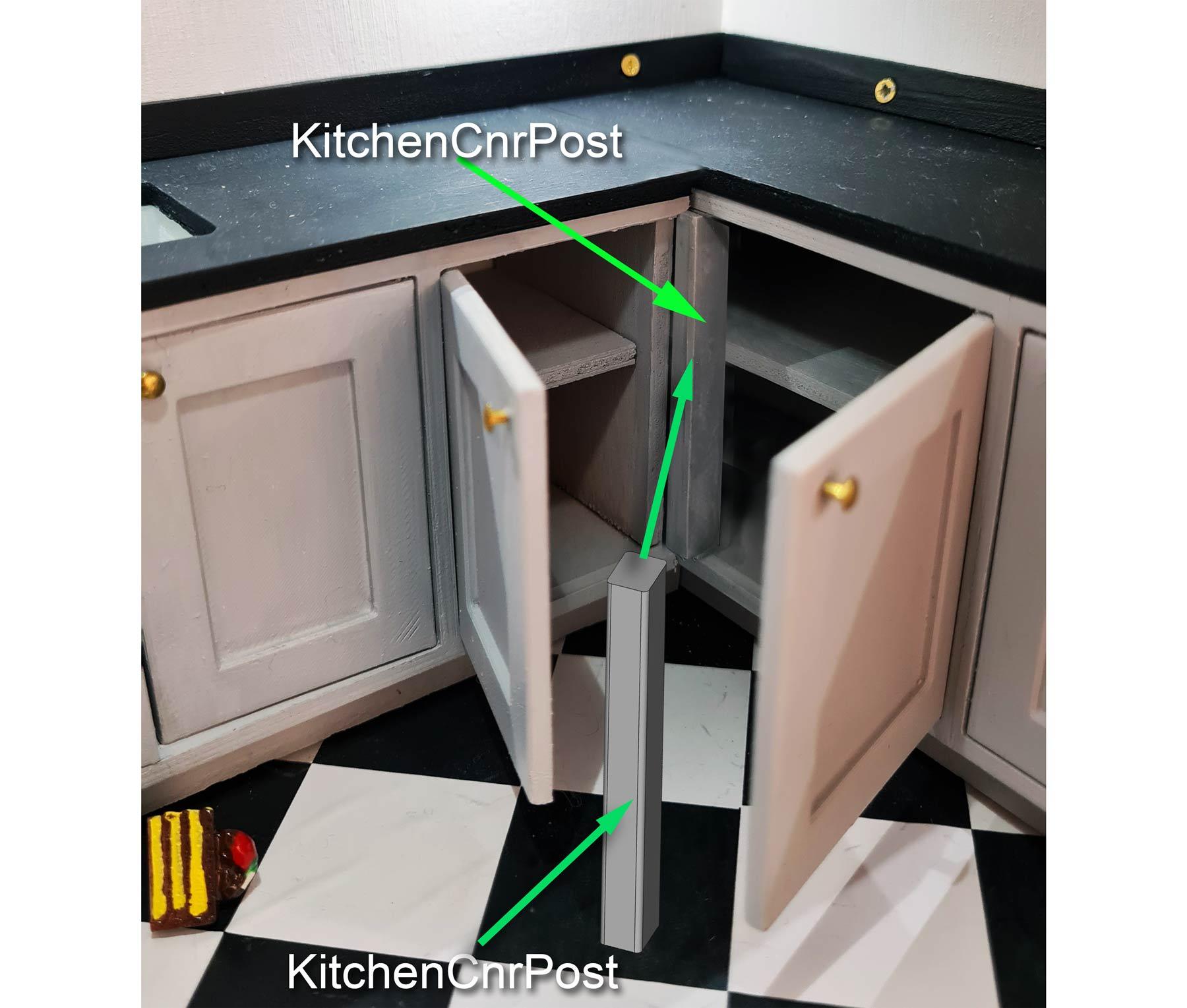
Pic 5. A corner post part name KitchenCnrPost is glued to the 3D printed frame where the doors meet at the corner.
3mm Plywood shelves can be added where required and should be cut around 43mm deep.
Downloads
Wall Carcass Construction
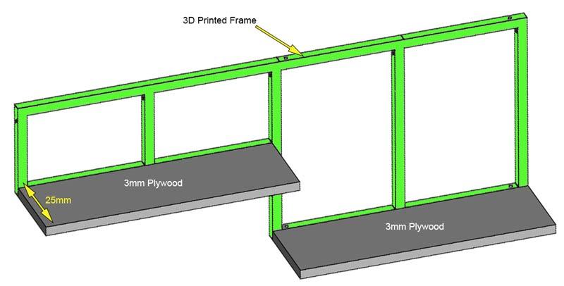
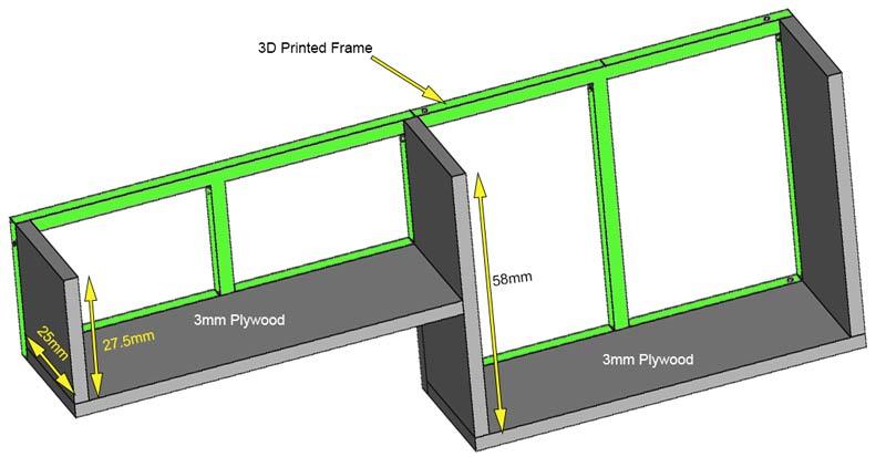
Pic 1. Wall units are built in the same way but use 25mm deep strips ( total 29mm deep 336mm real world depth).
Pic 2. Detail from rear of the kitchen wall units showing construction.
Larder/fridge/Oven Unit Carcass Construction
Pic 1. As before glue all the frames together for the whole run of units. The image shows a single part for clarity.
Using a 45mm deep length of 3mm plywood cut a length to fit the run of units and glue it ti the base of the 3D printed frame.
Pic 2. Then cut 3 off 176mm lengths of 45mm deep 3mm ply and glue it to the uprights to form the sides of the fridge and oven housings.
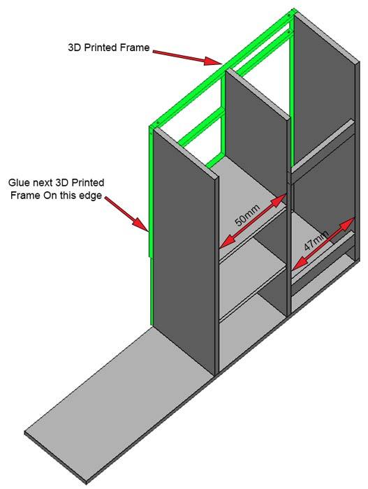
Pic 3. Cut 2 shelves out of 45mm ply 50mm deep to form the shelves for the oven and microwave. Glue them level with the lower 2 frame brackets.
Cut 2 off 10mm x 47mm stop brackets from 3mm ply and glue them flush with the rear of the fridge freezer cabinet.
Position these brackets towards the top and bottom of the fridge/ freezer.
These hold the fridge freezer in it's correct position in the housing.
If not using my fridge freezer then cut 4 off 47mm x 50mm and use as shelves.
Pic 4. Print "OvenFixingBracket.stl) 2 0ff (if fitting my oven & microwave).
Fitted behind the microwave and conventional oven to hold them in place.
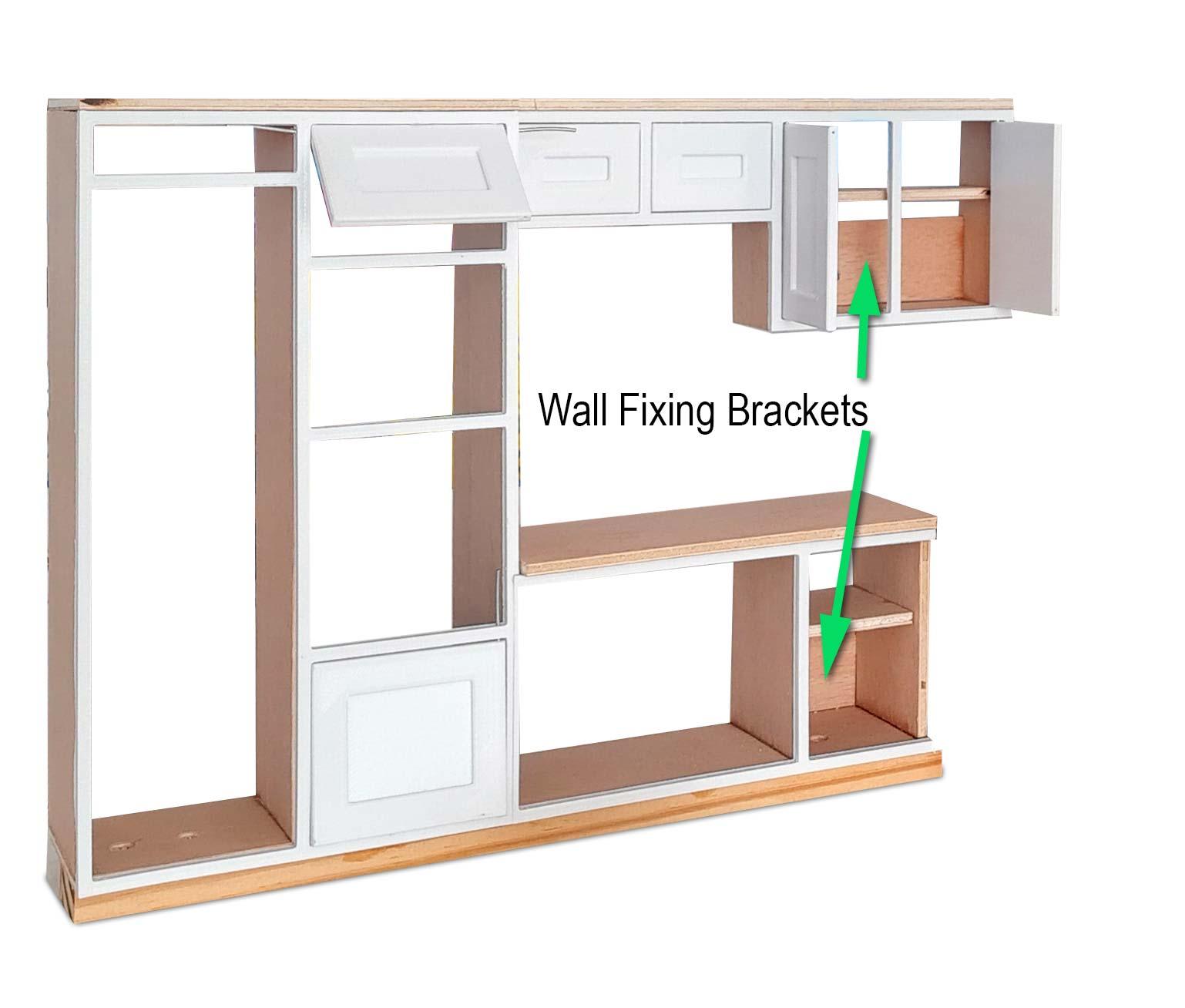
Pic. 5 Cut some fixing bracket out of 3mm plywood and glue into these locations. Drill 2.5mm holes in the center of these brackets. M2 wood screw will fix through these holes to the rear Doll House wall once the kitchen is completed.
Paint the carcasses pelmets etc the same colour inside and out if the doors are a light colour.
If the doors are dark you will prob want to paint the carcasses etc a light grey or white.
Downloads
Joining Wall Units to Fridge Freezer/Oven Unit

Pic 1. Join the wall unit module to the Fridge/Freezer/Oven module with superglue. To strengthen the joint cut the pelmet out of 3mm ply and glue across the modules.
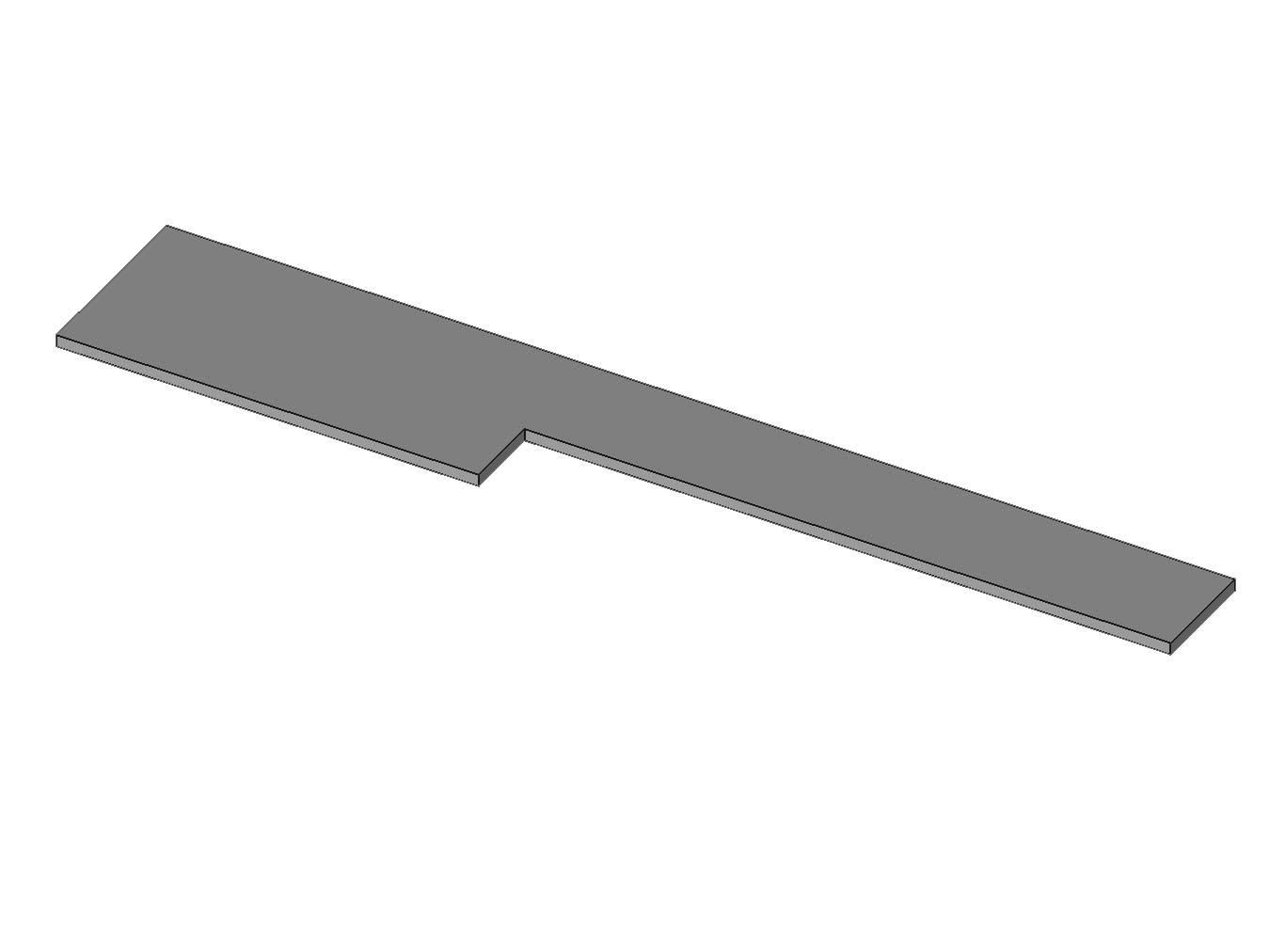
Pic 2. Plywood pelmet in place across the wall unit module and the Fridge/Freezer/Oven module.
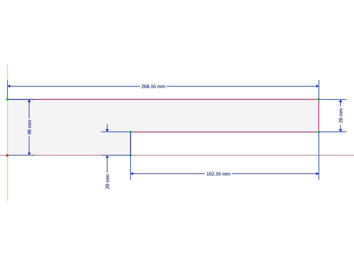
Pic 3. Plywood pelmet dimensions.
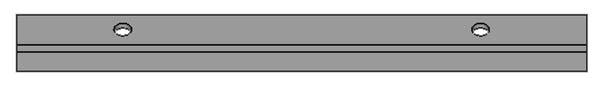
Pic 4 Pelmet side view.
Pic 5. The wall units have pelmets fitted under them wall.
"PelmitSink" is fitted under the smaller units above the sink.
Pic 6. "PelmetStd" goes under the standard tall wall units.
Cabinet Doors


All the cabinet doors are 3D printed and have holes for metal rod hinges.
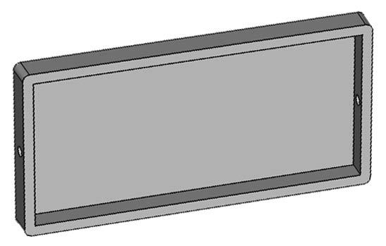
Pic 1. Door types with file names.
Pic 2. Door Locations with 3D file names.
Print out all the doors not forgetting the end panel.
Once printed, prime and paint them.
Pic 3/4. Fit the door knobs.
The kitchen cabinet door nobs were made from 8mm Round Head Brass Nails.
https://www.amazon.co.uk/dp/B078BPNV62?ref_=ppx_hzsearch_conn_dt_b_fed_asin_title_1
Pic 5. The knobs are fitted into 1mm holes in the cabinet doors using the "KitchCnrTemplate" to position the drill for the holes.
Pic 6/7. KitchenKnbSpacer
Push the brass pins through the hole in the door drilled above.
Slide the spacer under the brass pin until the head is flush with the top of the spacer.
This gives a 2mm gap. Pop a small bit of super glue on the rear of the pin where is passes through the back of the door.
Hang the Doors


Pic 1/2. Hang all the doors on the complete module by inserting the wire pin hinges through the frames into the doors.
Cut off any excess wire. You may need to drill out the 3D printed holes in the doors with a 1mm drill bit to clear them.
Note the picture shows the doors and cabinet carcasses unpainted as this image was taken during a test fit. Make sure all the cabinets and doors are painted and knobs fitted before hanging the doors.
Pic 3. You will now have completed rear and side units (ignore the temp worktops).
LED Downlights

Pic 1. LED downlights are simple white LEDs that fit into holes drilled in the 3mm plywood base of the wall units and illuminate the worktop below.
I have fitted two LEDs, one over the sink and one over the worktop below the taller wall unit. The LEDs are fitted with male header pins so the LEDs can be disconnected/connected with the rear wall unit. The wiring to the switch ends in female connectors.
Pic 2. At present you should have seperate completed kitchen units for the rear wall and side wall (ignore the temp worktops).
Slide the rear wall unit into the kitchen and open the wall unit doors. Mark the position of 2 holes to take the wire for the LEDs. Then remove the rear wall unit and drill the holes for the wires at the marked locations.
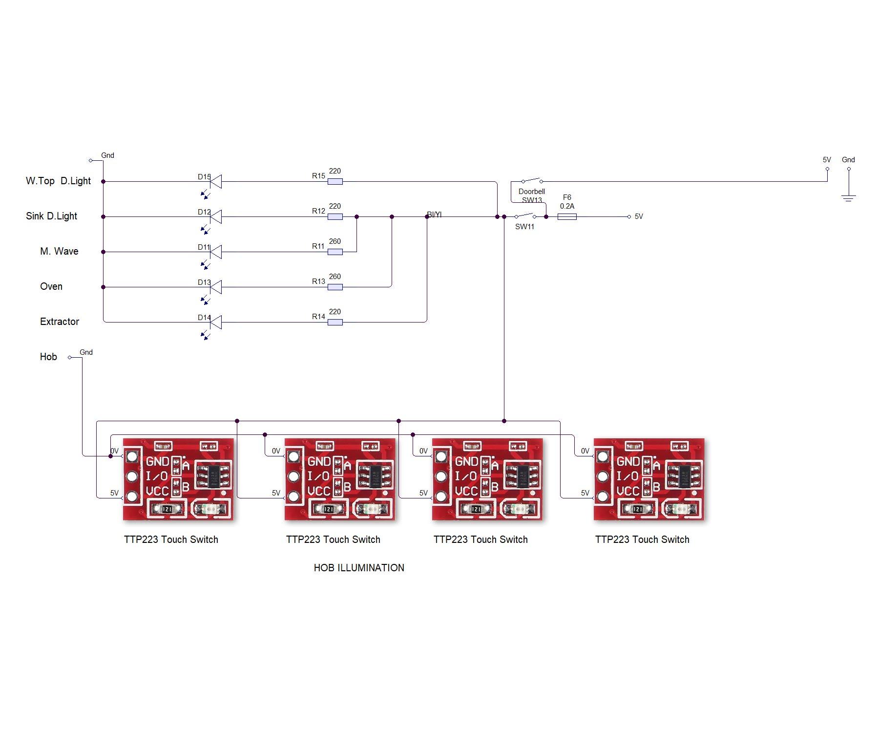
Pic 3. Wire the lights as per the schematic for "W.Top D.Lights".
See my Instructable Doll House Lighting for wiring details.
Slide the rear wall unit in place and connect the wiring to the two downlight LEDs.
Fix the rear wall unit in place through the fixing brackets with M2 wood screws.
Ensure all wiring for Hob, Extractor downlight etc is in place.
Slide the side wall units in and fix with M2 wood screws through the fixing bracket under the Hobs.
Worktops & Sink


Pic 1. Worktops are made from 50mm wide strips of 3mm plywood.
Cut a 324mm length for the side wall units (includes a bit of overlap) and a 122mm length for the end units.
Check they fit on the installed kitchen units.
Cut the hole for my Hob if fitted, see this Instructable for details.
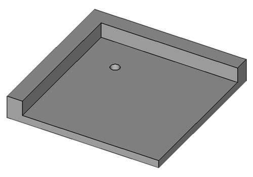
Pic 2. I have designed a sink for this kitchen. If you are using it cut a hole in the end worktop under the shrter wall units for the sink using the template in Pic. 3.
Pic. 3. Position this template on the worktop where the sink is going and then draw around the inside with a pencil.
Cut out the hole with a jigsaw.
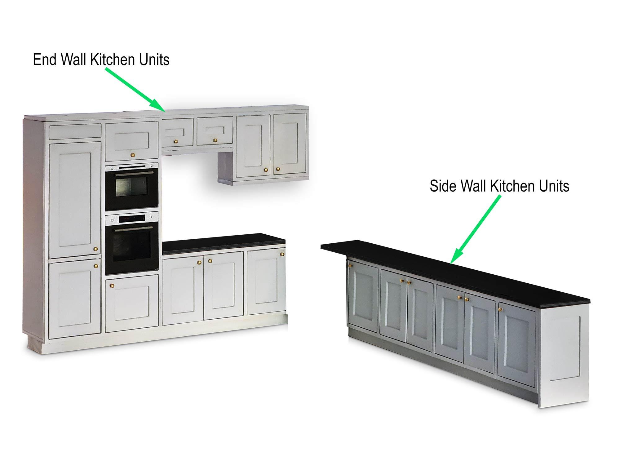
Paint the worktop in the colour of your choice.
I have used a metal tap from a doll house shop.
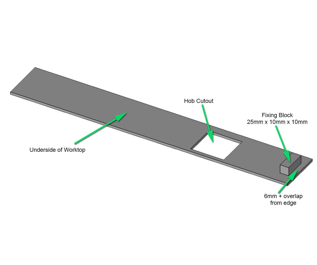
Pic 4. On the long lenth of worktop. Turn the worktop upside down and glue a small wood block (or 3D printed block) to the worktop.
To find the position of the block hold the worktop in place and draw a line from inside the end carcass with a cut down pencil. Glue the block on this line.
When the worktop is in place a M2 screw goes from the decorative end panel into the block to hold down the end of the worktop.
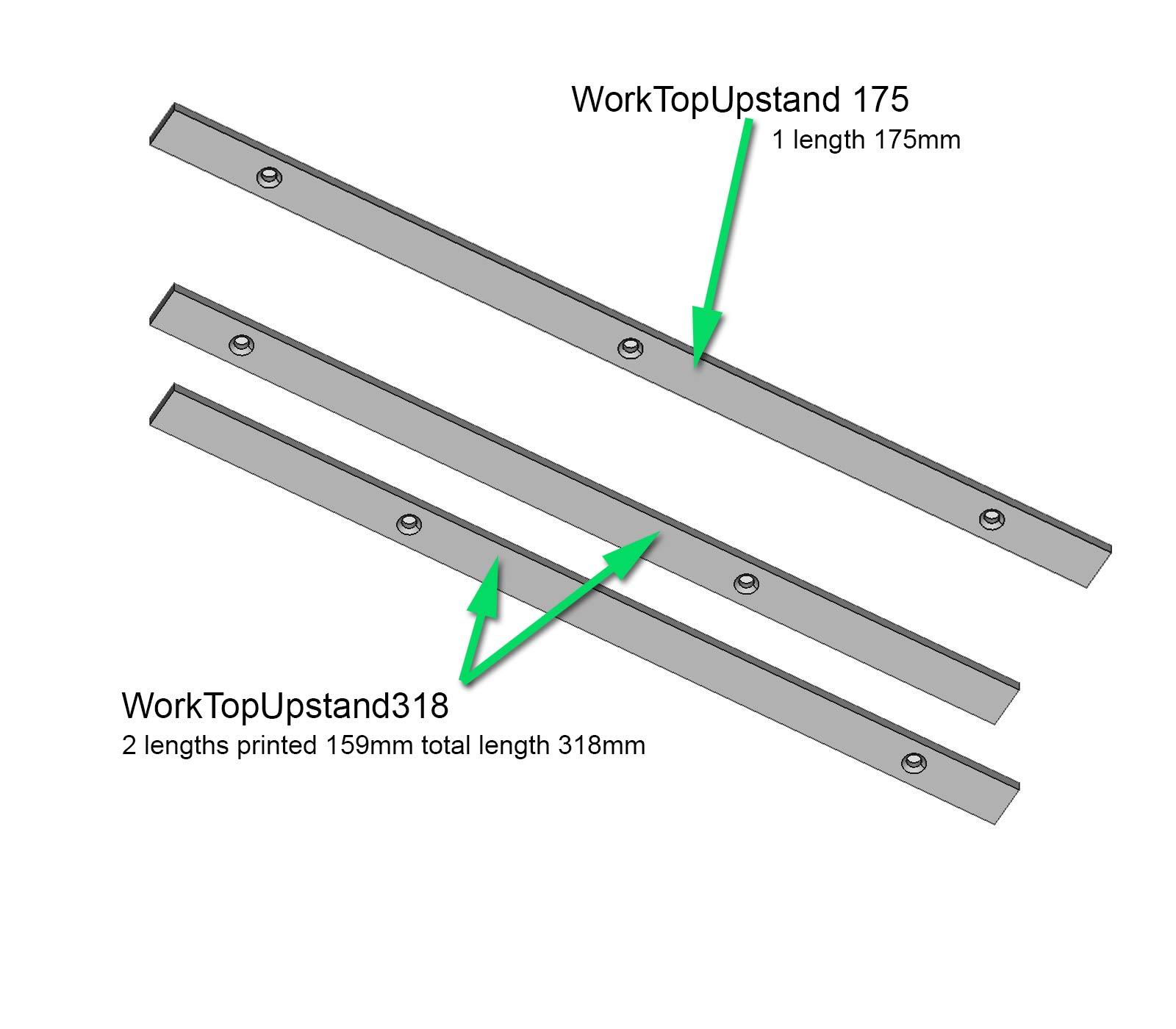
Pic 5. Worktop upstands are 8mm x 2mm x 318mm & 8mm x 2mm x 175mm and are made from timber or 3D printed.
Note if 3D printing the 318mm length it is made from 2 off "WorkTopUpstand 318" which are 159mm long.
3D print files are WorkTopUpstand 318 and WorkTopUpstand175.
Paint the upstands to match your worktop.
Fix the 318mm length first.
Upstands are fixed to the wall with M2 countersunk woodscrews.
The upstands also help hold the worktops on place.
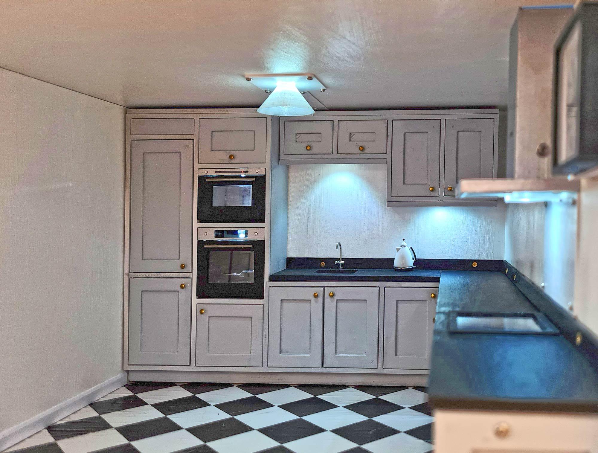
Pic 6. Shows the worktop/worktop upstands in place.