Simple and Cheap DIY Interactive Ambient Background Lighting.
79713 Views, 94 Favorites, 0 Comments
Simple and Cheap DIY Interactive Ambient Background Lighting.


This instructable will show you how to make a simple and cheap atmosphere background lighting system for your PC!
This simple system can be used with the AtmoWin software, or using the AtmoLight plugin in VLC (media player) , it connects to your PC using the standard USB connection on your arduino.
It has only one channel, but it still provides a nice effect.
A video of it in action:
This could be expanded to two channels, for more info see the last step.
Parts


You will need:
- An arduino
- 3x 2k2 resistors
- 3x an NPN transistor, capable of switching 12Volts (I will be using a 2SD1062)
- A 12Volt adapter (wall wart)
- A barrel jack
- A 12Volt RGB (common anode) LED Strip (I will be using this one)
- Header pins
- Some prototyping board (I will be using some perfboard)
Schematic
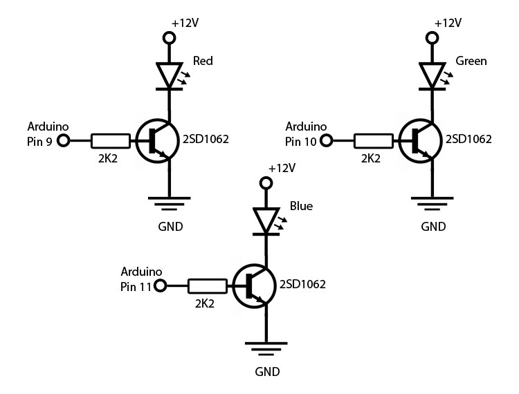
As you can see, the schematic is quite simple, it's just the same circuit three times, one time per color.
The Hardware


Cut a piece of perfboard so it covers all the pin headers on the arduino, make sure the holes in the perfboard line up with the holes in the headers.
It should be about 45 by 52 mm, leaving you with a grid of 17 by 20 holes.
Start assembling the circuit, I have added a picture showing how I built the circuit on my piece of perfboard.
All the components are on top of the board (the side without the solder rings) , the blue lines are the connections on the underside of the board.
If you are using a different transistor, make sure it has the same pinout as mine (Base - Collector - Emitter) , otherwise you will need to build the circuit differently.
If you are using the same LED strip that I am using, you can cut the strip into 6 smaller segments (on the indicated lines) , you can then add some wire between each segment, which makes it easier to position them.
Software Part 1: Arduino
This is the software that I wrote for the arduino.
I'm sure it could be done a lot better, but hey, it works!
Open up the attached sketch in the arduino IDE and upload it to your arduino.
This system only supports one channel, by default this is the sum channel, to change this find the following lines near the bottom of the sketch:
analogWrite(RedPin, RedSum); //change to RedLeft for left, RedRight for right, RedTop for top or RedBottom for bottom
analogWrite(GreenPin, GreenSum); //change to GreenLeft for left, GreenRight for right, GreenTop for top or GreenBottom for bottom
analogWrite(BluePin, BlueSum); //change to BlueLeft for left, BlueRight for right, BlueTop for top or BlueBottom for bottom
All the information you need is right there in the comments.
For example, if you want to use the top channel, change it to:
analogWrite(RedPin, RedTop); //change to RedLeft for left, RedRight for right, RedTop for top or RedBottom for bottom
analogWrite(GreenPin, GreenTop); //change to GreenLeft for left, GreenRight for right, GreenTop for top or GreenBottom for bottom
analogWrite(BluePin, BlueTop); //change to BlueLeft for left, BlueRight for right, BlueTop for top or BlueBottom for bottom
This could be expanded to two channels, for more info see the last step.
Downloads
Software Part 2: AtmoWin
In this step I will explain how to set up AtmoWin for this DIY interactive background lighting system.
If you want to use your interactive background lighting system all the time, use this, if you only wish to use it during movies (which I recommend) , see the next step.
If you don't have AtmoWin, you can download it from here , download links are at the bottom of the page.
One thing you will notice, is that most of it is in german, if you don't know german this can be a problem, but fear not! I will explain everything you need to change here and if you need more info, just ask!
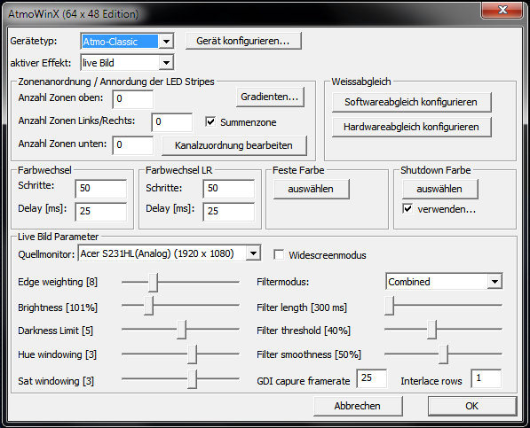
First of all, click "Gerät konfigurieren...", you will get a new window where you can select your arduino's COM port.
- "Gerätetyp:" set this to "Atmo-Classic"
- "aktiver Effekt:" set this to "live Bild"
- if you want to use the sum channel (default) , make sure to semect "Summenzone"
- "Anzahl Zonen oben:" set this to 1 if you want to use the top channel
- "Anzahl Zonen Links/Rechts:" set this to 1 if you want to use the left or right channel
- "Anzahl Zonen unten:" set this to 1 if you want to use the bottom channel
You can use the button "auswählen" under "Feste Farbe" to test out the hardware.
The other setting don't have to be changed, if you have multiple monitors, select the one you wish to use for the interactive background lighting under "Quellmonitor:".
Software Part 3: VLC


The AtmoWin software is quite CPU intensive, I only use it when watching movies or tv shows.
If you also only want to use it when watching movies or tv shows, you can set up the AtmoLight plugin in VLC media player.
If you don't have VLC (you should!) , you can download it from the official site.
To set up the plugin for this system, start VLC and go to Tools > Preferences .
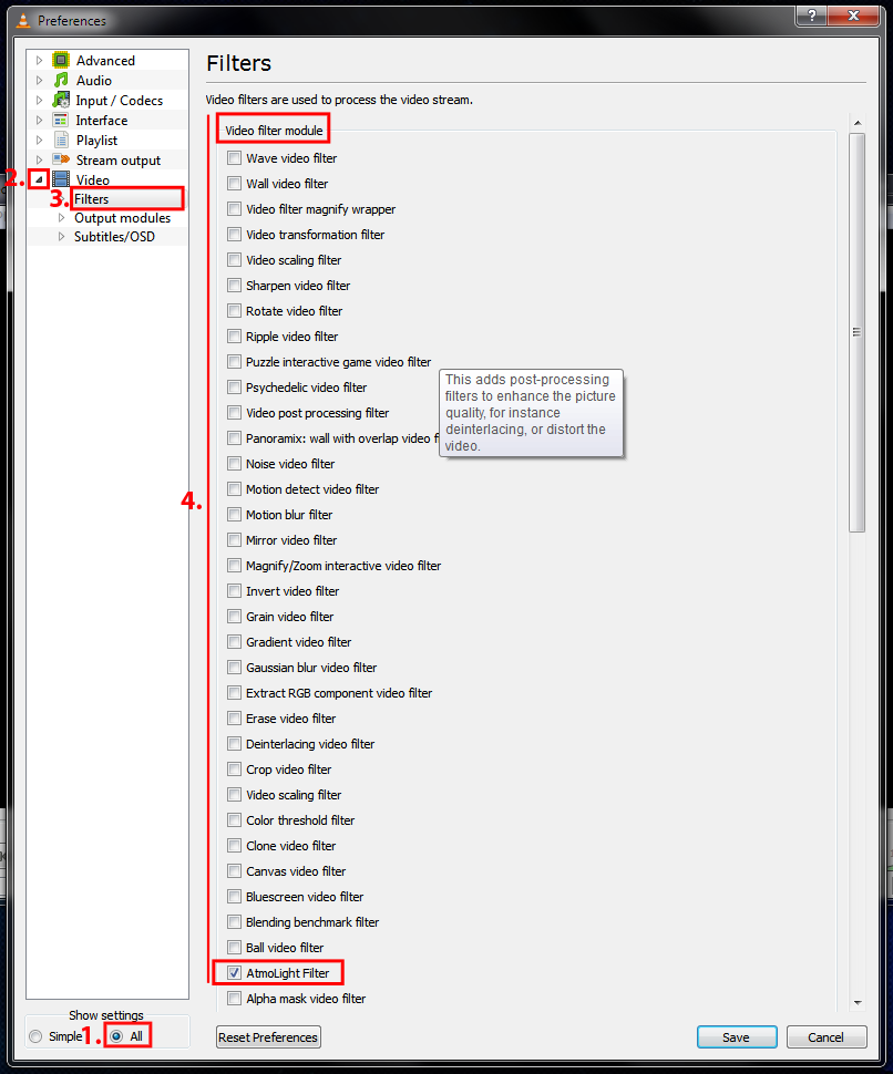
A new window will open up, in the bottom left corner, change "Show settings" to "All" , the window will change.
Click the little arrow next to "Video" and select "filters", on the right side of the window, you'll see a list, under "Video filter module " select "AtmoLight" , don't select it under "Video output filter module" or else you won't see the video anymore.
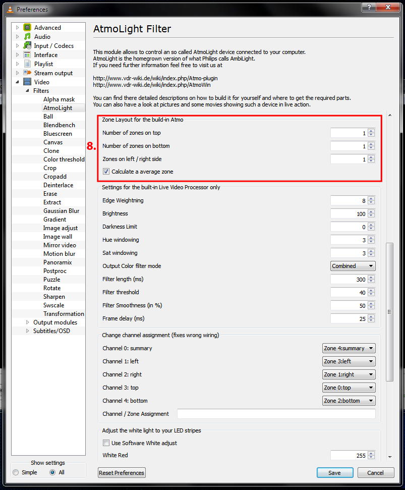
Now click the little arrow next to "Filters" and select "AtmoLight" .
- Set "Device type" to "Classic AtmoLight"
- Set "Serial Port/Device" to your arduino's COM port (you have to type this)
- Find "Zone Layout for the build-in Atmo" and change "Numbers of zones on top" , "Number of zones on bottom" and "Zones on left / right side" to 1 if they're not set to 1 allready, make sure to select "Calculate a avarage zone"
You shouldn't need to change any other setting.
Now if you open a video in VLC, your interactive background lighting system should work!
Done!
Plug in the wall wart and connect it to the barrel jack (the one in your circuit, not the one on the arduino) .
Connect your arduino to your pc, fire up VLC or AtmoWin and you are ready to go!
Enjoy your simple, cheap DIY interactive background lighting!
A video of it in action:
Possible Expansion.
It is possible to add a second channel to this system, the arduino has a total of six output pins that support PWM.
You can build the circuit again and connect the transistors to pins 3, 5 and 6 instead of 9, 10 and 11.
I have attached an alternate arduino sketch, by default it is set up to use pins 9, 10 and 11 for the left channel and pins 3, 5 and 6 for the right channel, you can change this easily by editing the 6 lines near the bottom of the sketch (see step 4 for more info) .