Single Stage Coilgun That Launches Projectiles at 14.5 M/s
by GyanKalra in Circuits > Electronics
220 Views, 3 Favorites, 0 Comments
Single Stage Coilgun That Launches Projectiles at 14.5 M/s
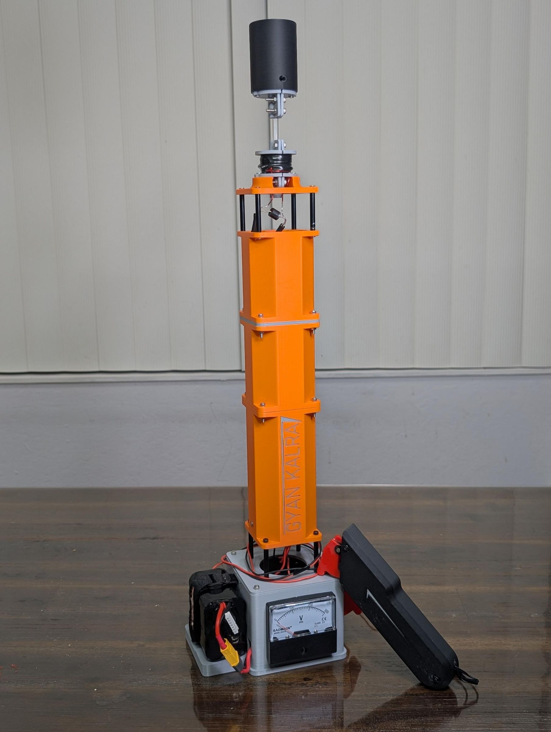
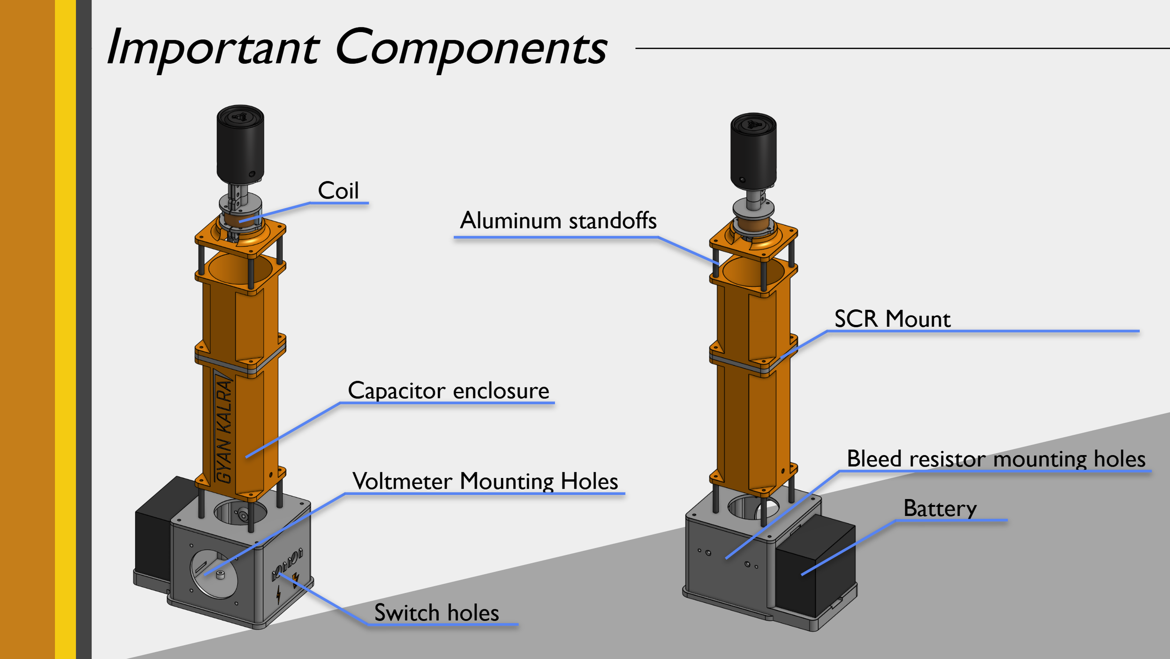
Single Stage Electromagnetic Coilgun
In this project, I built a single stage electromagnetic coilgun capable of launching a bearing steel projectile to a height of 10.7 meters at an initial velocity of 14.5 m/s. This was built as a physics project exploring concepts beyond AP Physics 1, specifically electromagnetic induction, capacitor discharge circuits, and the force on ferromagnetic materials in a magnetic field.
How it works:
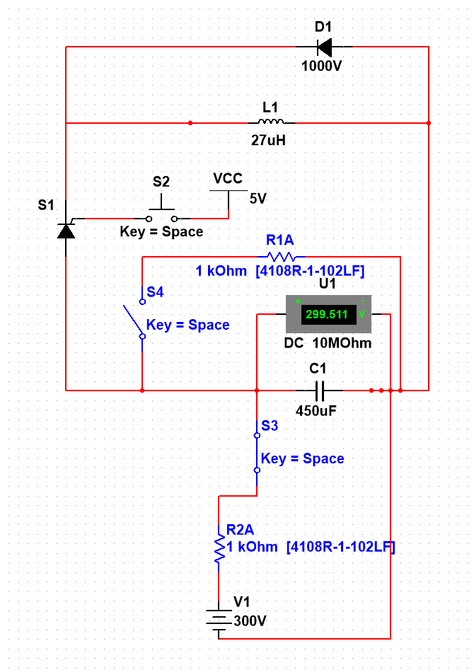
A 6S lithium ion battery powers a boost converter that charges a 450μF capacitor to 300V, storing 20 joules of electrical energy. When the trigger is pressed, a Silicon Controlled Rectifier (SCR) discharges the capacitor through an 18 AWG electromagnetic coil in under a millisecond, generating a magnetic field that pulls a bearing steel projectile into the center of the coil. The capacitor discharge ends before the projectile reaches the center, preventing it from being pulled back in and allowing it to exit at full velocity. A flyback diode protects the circuit from the voltage spike caused by the collapsing magnetic field.
Results:
- Initial launch velocity: 14.5 m/s (52.2kph/32.5mph)
- Average height: 10.73 meters
This project was inspired by large scale electromagnetic launch systems like the US Navy's EMALS system used to catapult aircraft off aircraft carriers, and explores the same physics at a scale that can be built and tested at home.
Safety Note: This device charges capacitors to 300V, which is potentially lethal. Always discharge the capacitor through the bleed resistors before handling any part of the circuit.
Supplies
Electronics
- 450μf 300v Capacitor - Used to rapidly discharge current and create a burst of electromagnetism
- 300v Boost converter - Used to boost 22v to 300v in order to charge the capacitor
- 18 AWG Enameled Copper Wire - Used to make the electromagnetic coil
- 100W 1kΩ resistors (2x) - Used to discharge the capacitor safely and prevent inrush current overloading the boost converter
- Silicon Controlled Rectifier 50RIA120 Thyristor (SCR) - Used to rapidly discharge stored capacitor energy into the electromagnetic coil
- 10A10 Rectifier Diode 10A 1000V - Used to prevent backcurrent from the collapsing magnetic field from damaging the SCR
- 5 watt 33Ω resistor - Used to reduce current from the 9v battery to trigger the SCR
- 9V battery - Used to provide the trigger input for the SCR
- XT60 Connector - Used to connect the Li-ion battery to the boost converter
- Auline 21700 4000mAh 6S 22.2V Battery - Used to charge the capacitor
- Toggle Switch - Used to toggle capacitor charging and discharging
- Momentary Push Button - Used to activate the trigger for the SCR
- 9v Battery - Used to provide power for the trigger signal
- 24AWG Wire - Used for power transfer and signal
- 12AWG Wire - Used for high current connections
3D Printing Supplies
- ASA Filament - Use ASA filament for the coil guide as it is durible and heat resistant. If you can, use ASA for the entire structure.
- Other filaments can be used for other structural components.
Soldering Supplies
- Soldering Iron - Used to heat up solder and make electrical connections
- Solder - Heated up to make electrical connections
- Flux - Removes oxidation from solder joint and spreads solder evenly
- Wire Strippers - Remove insulation from the wire
Additional Hardware
- M3x35mm Standoffs - Used to hold the pieces of the coilgun together
- Apex RC Products 5 Pack 20mm x 300mm HD Rubberized Battery Straps - Used to hold the battery
- Heat set inserts - Used to allow screws to be used in the 3D prints
- Screws - Used to assemble the frame and hold electronics in place
- Double sided tape - Used to secure small components
- 4mm × 16mm steel dowel pin - The projectile, ensure it's bearing steel or another ferromagnetic material
- 5mm internal diameter acrylic tube - Acts as the barrel for the projectile
3D-Print the Parts
STEP Files: All part files can be found on this printables page. All files are in the STEP, allowing you to modify them after downloading.
Notes
- Files that begin with a number (ex: 4xArm-PA6-CF.step) indicate how many times that part should be printed
- When printing this I used ASA for the main body due to it's elevated heat resistance. These can both be printed in PLA but the results will be less durable.
- ASA produces harmful particles, so it is recommended to print in a well-ventilated area. A heating chamber benefits these materials as it reduces warping
Add Heat-set Inserts to Prints
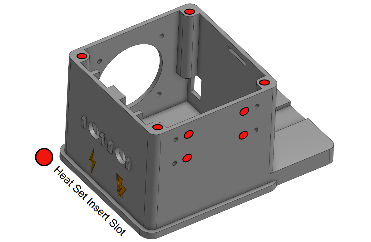
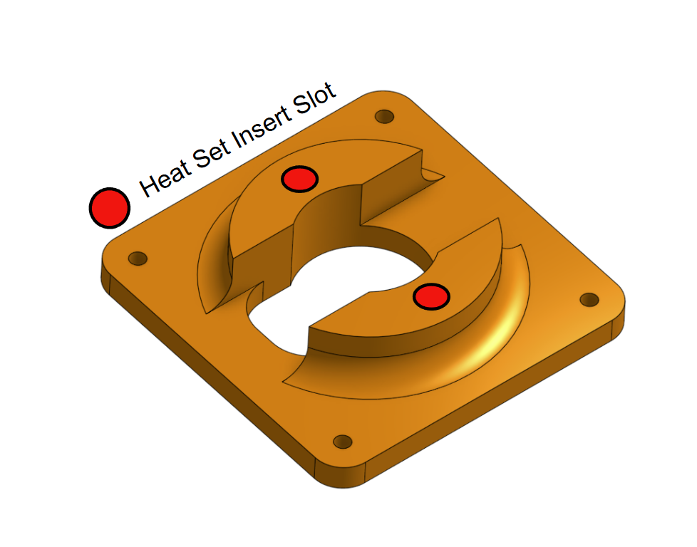
Introduction to heat-set inserts
Heat-set inserts are small brass threaded tubes with knurls on the outside which you melt into prints with a heated soldering iron. This allows reusable threads and strong connections.
Instructions
Heat up your soldering iron and place the heat insert on top of the hole. Once the soldering iron is heated, place the tip into the threaded hole and push down so that the insert melts into the plastic. If it does not push in, increase the temperature.
Notes
Any M3 heat set insert will work for this build. Use whatever length you have available, the exact depth is not critical as long as the insert is flush with the surface and the insert does not protrude through the other side.
Different heat settings for your soldering iron will be used for different 3D printer filaments. From my experience the following settings worked but you may have to experiment:
- ASA: 500° F
It is better to have a lower temperature than a higher temperature, as a high temperature can cause the insert to go in too far and weaken the surrounding plastic. I recommend practicing on a test print to figure out the proper temperature and timing.
Sometimes some plastic will bulge at the top as you push the insert in.
- You can trim it with flush cutters/filament cutters once the part cools.
- Make sure the insert is flush with the surface of the part.
Assembling the Base
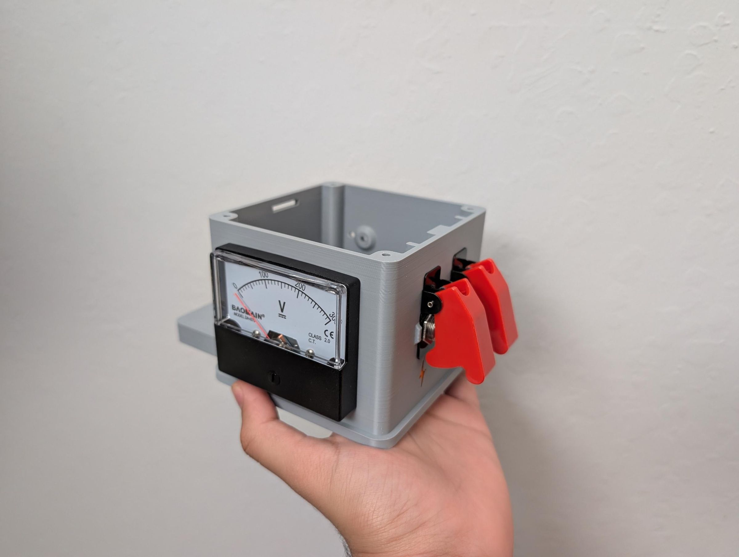
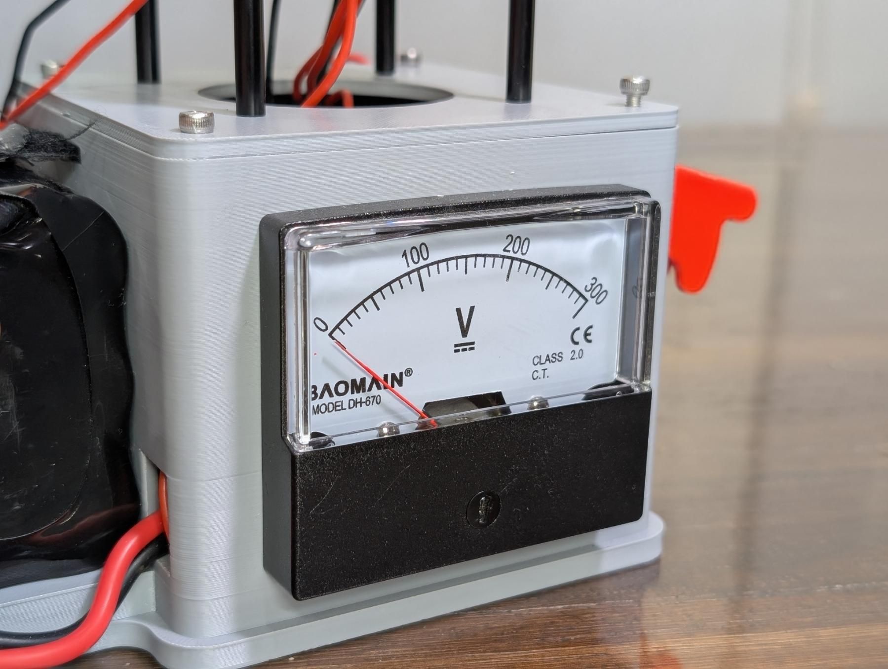
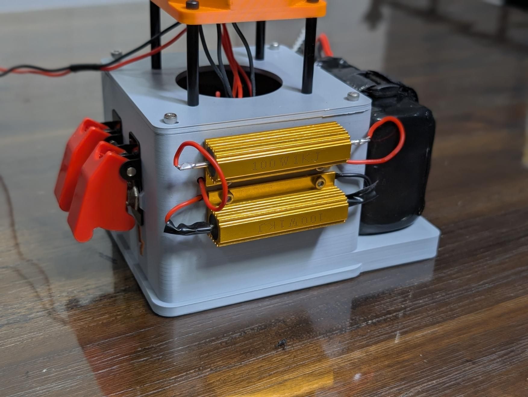
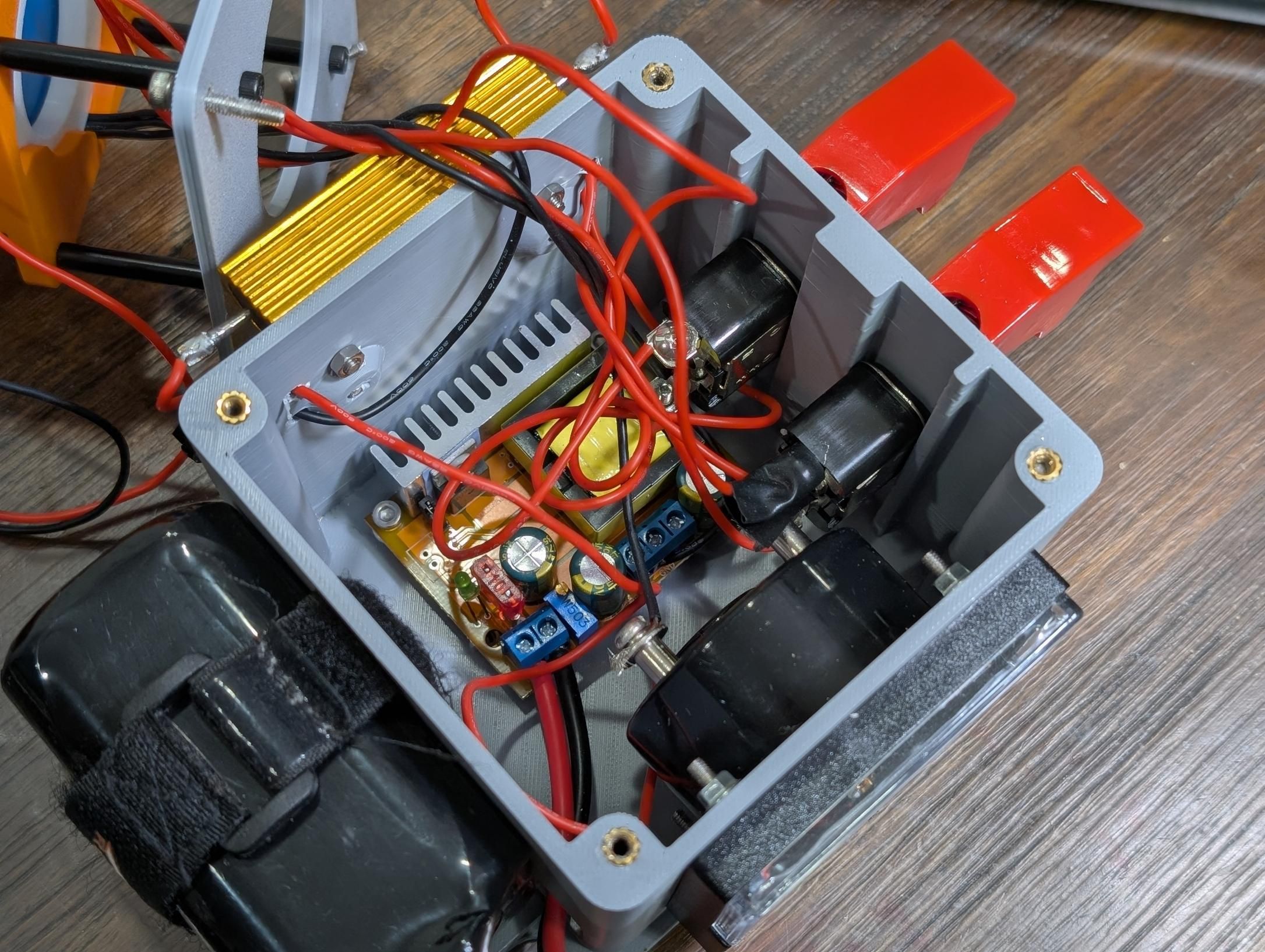
Connecting the Boost Converter
- Attach an XT60 connector to the input of the boost converter.
- Connect two 24 gauge wires to the output of the boost converter.
- Connect a lithium ion battery to the xt60 connector.
- Connect a multimeter to the 24 gauge wires to the output of the boost converter.
- Adjust the output of the boost converter to 300v with the adjusting screw.
- Screw the boost converter into the base and ensure the XT60 connector exits through the side port.
Mounting the Voltmeter
- Connect the voltmeter's screw terminals onto two 24 gauge wires.
- Slide the wires into the large hole in the front of the base and push the voltmeter into the designated screw holes. Ensure the voltmeter is facing right side up
- Fasten the voltmeter with nuts on the top two screws.
Mounting the Bleed and Inrush Current Resistors
- Solder two 24 gauge wires onto either side of the two 1kΩ resistors.
- Screw the two resistors into the rear holes of the base, with the top resistor being mounted upside down.
- Route the 24 gauge wires through the wire holes placed beside the resistors so that they are inside the base.
Mounting the Charge and Discharge Switches
- For the Charge switch, connect the boost converter's output wire to the input screw terminal of a switch. Connect the wire soldered to the inrush current resistor (the top resistor) onto the output of the charge switch. You should still have one wire on the other side of the resistor, this will connect to the capacitor. Slide the lever of the switch through the mounting hole, ensuring that the off position points downwards. Mount it with the nut provided with the switch.
- For the discharge switch, connect one wire from the bleed resistor (the bottom resistor) to the input of the switch lever. Connect the other wire from the bleed resistor to the capacitor positive terminal. Slide the lever of the switch through the mounting hole, ensuring that the off position points downwards. Mount it with the nut provided with the switch.
Notes:
- Inrush Current Resistor (top resistor): When the charge switch is flipped, the capacitor draws a large surge of current from the boost converter. This resistor limits that surge, preventing the boost converter from being damaged or shutting off.
- Bleed Resistor (bottom resistor): After use, the capacitor stores 300V even when the boost converter is off. Flipping the discharge switch routes current through this resistor, safely draining the capacitor before you handle the circuit.
Central Tube and Capacitor Assembly
Assembling the Central Tube
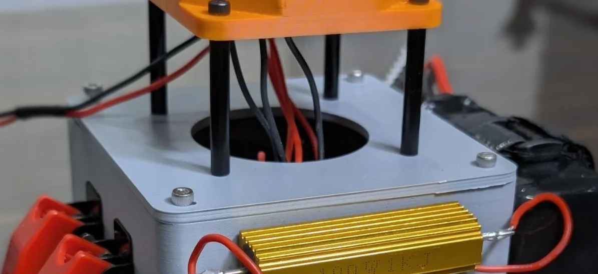
- Locate the lid of the base and mount four standoffs onto the central screw holes.
- Place the longest hexagonal tube on top of the assembly and attach it by screwing into the standoffs.
Connecting the Capacitor
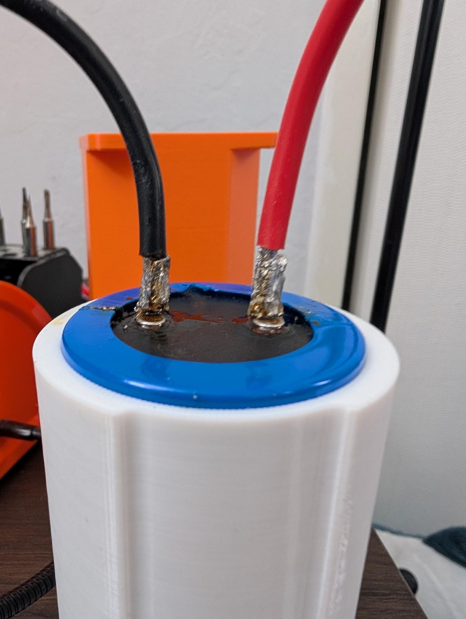
- Place your capacitor into the TPU sleeve.
- Pull the bleed resistor wires, boost converter output wires, and voltmeter wires out and through the hexagonal tube. Add two more long wires, at least 4 feet long, and ensure they stay inside the tube, they should route outside of the base through the gaps between the standoffs. These wires will be soldered to the SCR and will act as your trigger.
- Slide the TPU sleeve into the tube while ensuring the wires are in the designated wire channels in the sleeve and are not being compressed.
- Line up the holes on the TPU sleeve and the hexagonal channel. Push a short m3x5mm screw into the hole in order to secure the capacitor.
- Solder the voltmeter, boost converter, and discharge resistor wires to the capacitor leads along with a 12 gauge wire for output into the electromagnet that will be made later.
- Positive terminal:
- Wire from resistor connected to boost converter
- Wire from switch connected to resistor for discharge
- Positive wire from voltmeter
- 12 Gauge output wire
- Negative Terminal:
- Ground wire from boost converter
- Wire from discharge resistor
- Ground wire from voltmeter
- 12 Gauge ground wire
Silicon Controlled Rectifier Connection (SCR) and Electromagnet Assembly
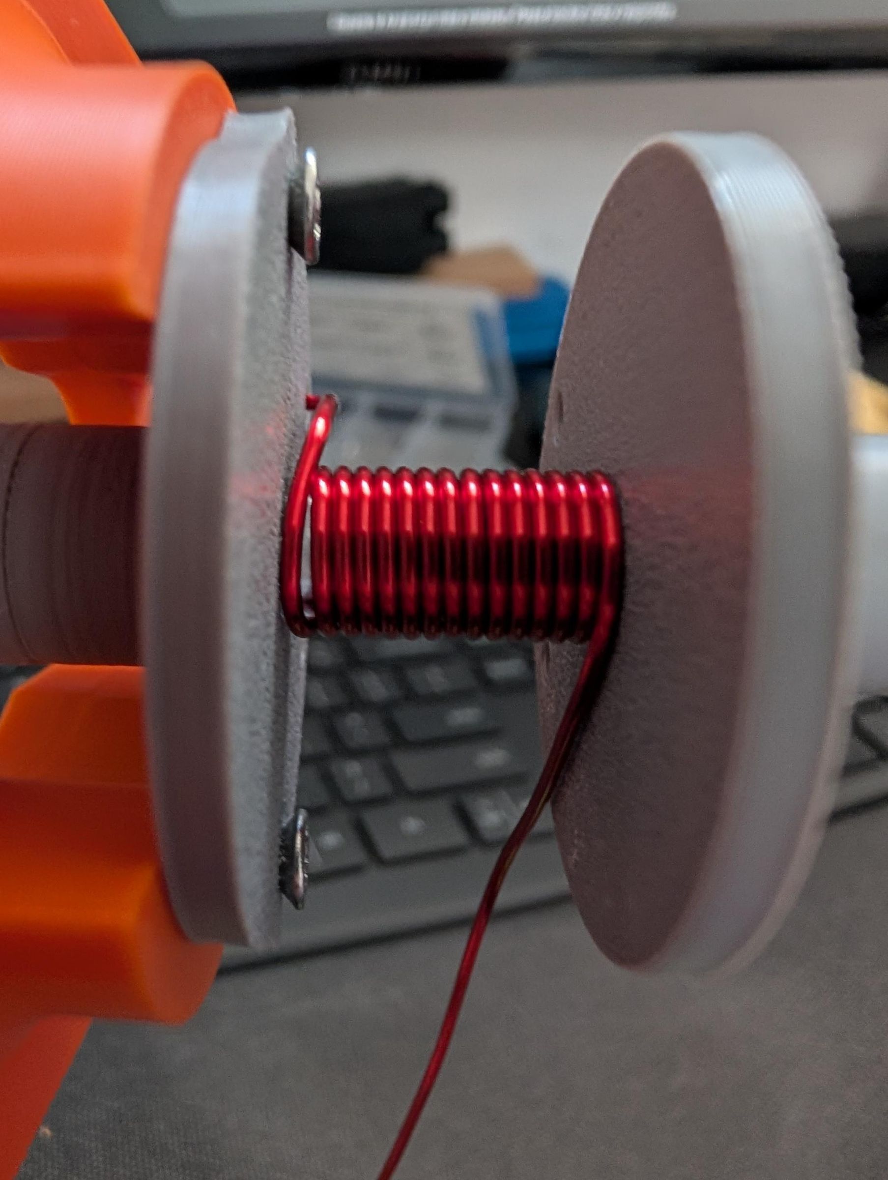
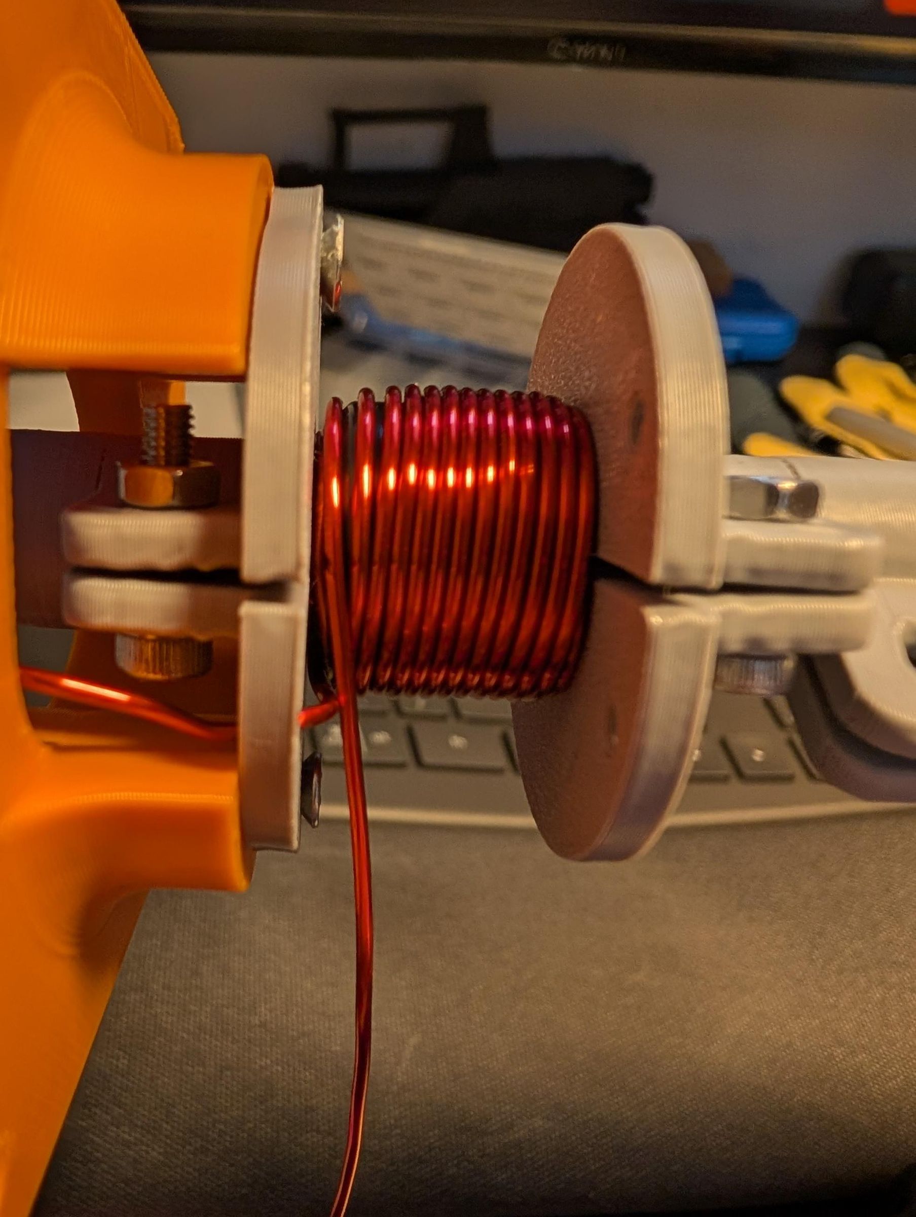
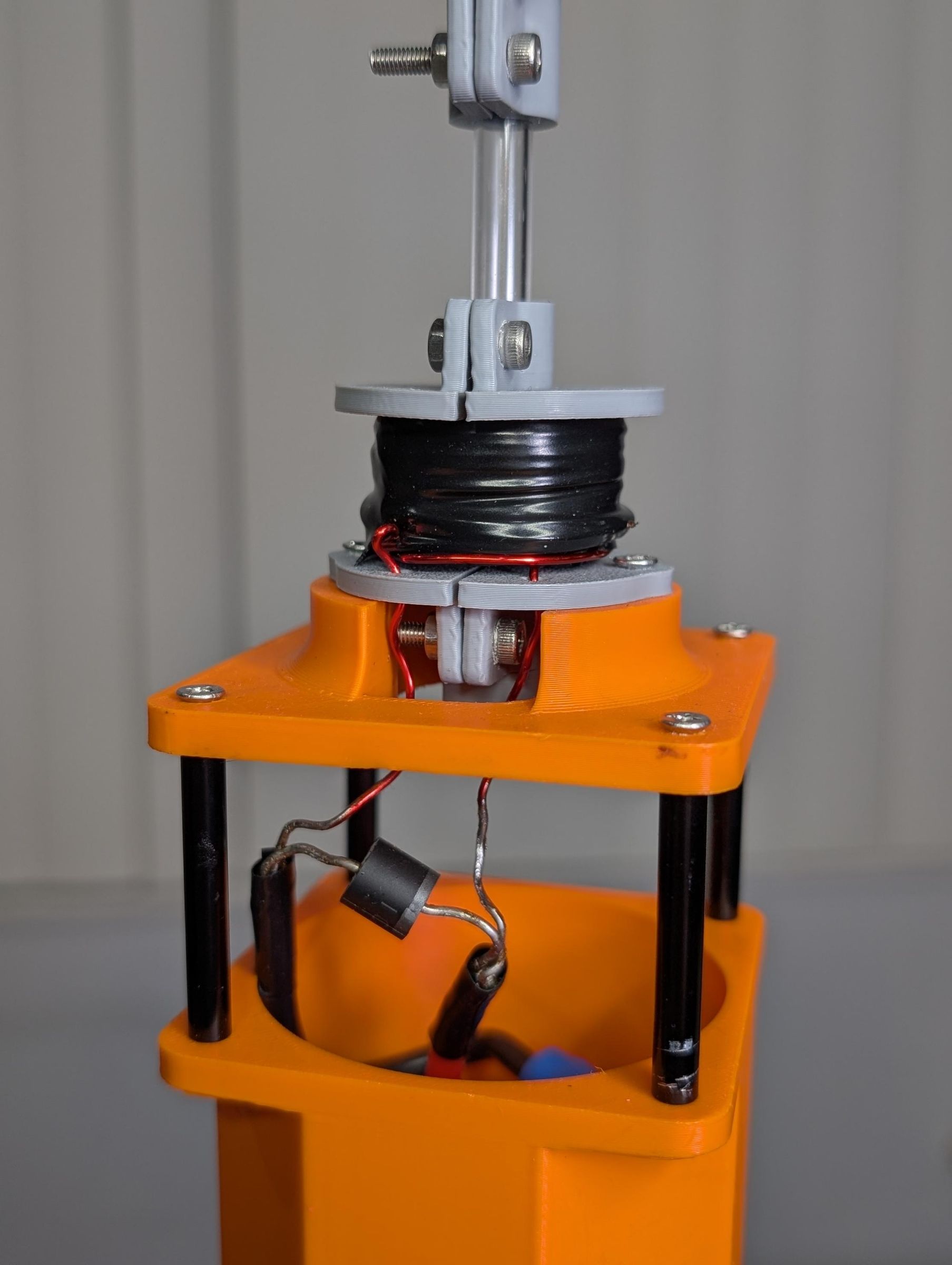
SCR Mount Assembly
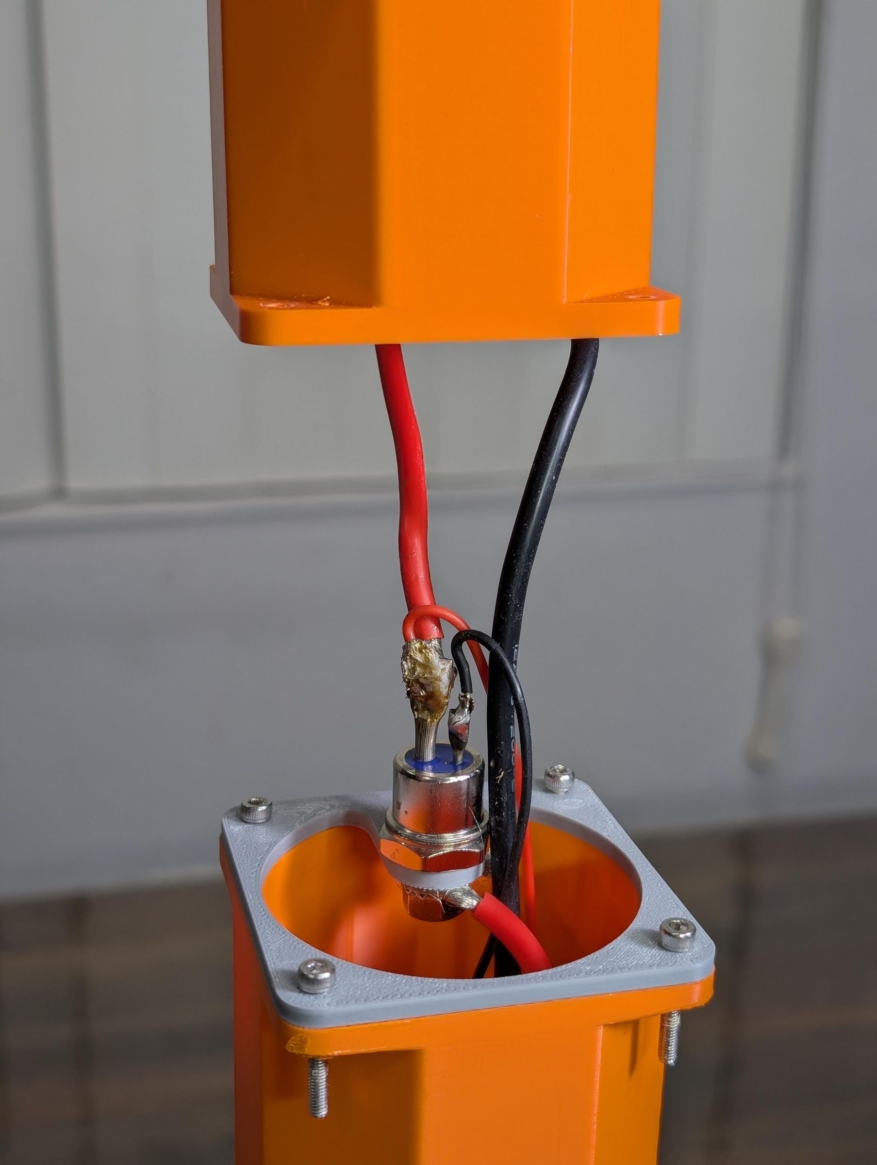
- Pass the 12 gauge output wire and 12 gauge ground wire through one of the two short hexagonal shafts.
- Push the SCR lug into the mount and strip enough of the 12 gauge output wire to wind around the SCR lug.
- Tighten the nut around the SCR and ensure a secure connection. The ground wire should be passing through the larger hole in the SCR mount.
- Temporarily screw the SCR mount and short hexagonal shaft together.
- The SCR has three terminals:
- Stud (large threaded lug) = Anode: this is where the 12 gauge output wire from the capacitor positive connects
- Large flat lug = Cathode: this is where the 12 gauge wire going to the electromagnet connects, and where the ground wire of the 9V trigger circuit connects
- Small lug = Gate: this is where the 33Ω resistor and trigger wire connects
- Solder the 12 gauge electromagnet wire onto the large flat lug (cathode). Solder one 24 gauge trigger wire onto the large flat lug (cathode) and the other 24 gauge trigger wire onto the small lug (gate). Make sure the other ends of the trigger wires are still unused and outside the assembly.
- Remove the previous temporary screws to secure the SCR mount and attach the second hexagonal shaft on top of the SCR with a screw and nut.
Electromagnet Assembly
- Cut 80mm tube of 5mm inner diameter acrylic tubing. Place the tube cap on the bottom and slide on the two coil clamps. Use the coil spacer to spread them the correct distance of around 16mm. Place the end of the coil through the small hole. Wrap the coil with 15 turns per layer. There can be any amount of layers, I had 13.
- The more layers there are the more magnetic force there is, although as there are more layers the layers get farther away from the projectile and cause diminishing returns, while also increasing resistance. It is good to experiment.
- Strip the ends of the copper wire and tin it with solder. Solder the output wire and ground wire onto the sides of the electromagnet and solder the flyback diode from the negative to positive direction. This is to prevent current backflow.
- Mount the electromagnet clamp onto the mounting piece. Connect the electromagnet mounting piece to the hexagonal shaft with standoffs.
Notes:
Winding the wire around the SCR stud:
Strip about 1 inch of insulation from the 12 gauge wire and wrap it around the stud before placing the nut on top. Tighten the nut hand tight plus a quarter turn. Do not overtighten, this can crack the stud mount.
Winding the coil:
- Keep your winding direction consistent across all layers
- After completing each layer, apply a small amount of electrical tape to hold it in place before starting the next layer
- The enameled insulation on the ends of the copper wire must be fully removed before tinning. Sand it off or briefly hold a flame to it until the coating burns away, then tin immediately.
Trigger and Final Assembly
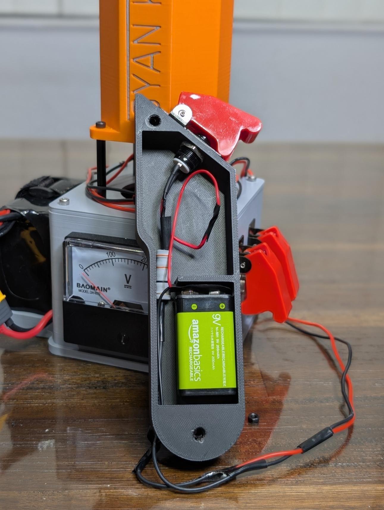
Trigger Assembly
- Push the pushbutton into the trigger shell, use a nut to secure it.
- Connect the ground of the 9V battery to the trigger wire that connects to the large flat lug (cathode) of the SCR and solder it.
- Solder the power of the 9v battery to the pushbutton.
- Connect the 5W 33Ω resistor to the output of the pushbutton and solder the second trigger wire, the one connected to the small lug (gate) of the SCR, to the other end of the resistor.
- Place the lid of the trigger shell on top of the shell and pass a screw through the two holes in the casing. Use a nut to fasten the two parts together.
Final Assembly:
- Slide the battery strap into the designated slits on the base.
- Connect the lid of the base to the base with 4 screws.
Notes:
Why the 33Ω resistor is necessary:
The SCR gate is sensitive and without a resistor, the 9V battery would dump uncontrolled current directly into the gate, potentially damaging or destroying it. The 33Ω resistor limits gate current to ~197mA, which is above the 100mA needed to trigger the SCR reliably while staying well within its 2.5A maximum gate current rating.
First-fire checklist before closing the assembly:
- Capacitor charged to 300V
- All exposed connections insulated with heat shrink
- Discharge switch in the off position
- Coilgun pointed in a safe direction away from people
- 9V battery connected to trigger circuit
How to Use It
Charging
- Ensure that the discharge switch is in the off position
- Connect the battery to the XT60 connector
- Flip the charge switch on. The voltmeter will begin rising towards 300v.
- Once the voltmeter reads your desired voltage, flip the charge switch off.
Loading and firing
- Drop a projectile into the barrel from the top. It should fall and rest at the bottom of the coil.
- Point the coilgun in a safe direction.
- Press the trigger button. The projectile will launch in whatever direction the coilgun is pointed at.
Discharging (every time you're done firing)
- Flip the discharge switch on
- Watch the voltmeter and wait until it reads 0v
- Flip the discharge siwtch off
- Disconnect the battery