SitSense


Have you ever caught yourself slouching at your desk, neck craned forward like a tech-savvy turtle, wondering why your back feels like it’s plotting against you? That’s me, bad posture and all. But instead of just grumbling about it, I decided to take matters into my own hands. Introducing SitSense, your personal posture enforcer that’s as relentless about good posture as your mom telling you to sit up straight!
Here’s how it works: SitSense uses an ESP32-S3, an IMU sensor (MPU6050), and some clever programming to monitor how you’re sitting. If your posture goes rogue a buzzer kicks in to politely nag you back into proper form, if you don't correct it for more than 10 Sec, your PC gets locked, no negotiations! To unlock it? Sit upright and reclaim your throne of productivity.
But that’s not all! SitSense comes in two flavors:
- Simple Version: A quick and easy program that compares your posture to a predefined baseline. Effective, but basic.
- Advanced Version: The showstopper! With a custom EdgeImpulse-trained model, this version can adapt and detect postures with far greater accuracy, making it a true posture police.
Sleek Hardware Design:
- The ESP32-S3 with Camera Module opens up endless possibilities beyond this project. Think gesture recognition, face tracking, or even AI-driven fitness coaching!
- It’s housed in a sleek, 3D-printed case with a magnetic clip design, so you can attach it to your body, the wall, or just about anywhere.
Whether you’re a DIY enthusiast or just someone tired of their posture wreaking havoc, SitSense is here to save your spine (and your productivity). Ready to sit up straight and dive in? Let’s build something awesome together!
Supplies


Components:
1x FireBeetle 2 Board ESP32-S3 with camera or FireBeetle 2 Board ESP32 S3
1x MPU6050
1x Buzzer
8x 5mm Magnet
Choosing the Right FireBeetle 2 Board ESP32-S3 for Your Needs
When building SitSense, selecting the right microcontroller is crucial, not just for this project but for your future endeavors. Here, I’ll guide you through the two options I considered, FireBeetle 2 Board ESP32-S3 with Camera and FireBeetle 2 Board ESP32-S3, and why I opted for the version with a camera.
The FireBeetle Board S3 stands out for its AI capabilities and built-in battery management, making it ideal for portable, efficient, and AI-driven projects.
- Option 1: FireBeetle 2 Board ESP32-S3 (Standard Version), Why Choose This?
- If you are focused solely on IoT projects that don’t require visual inputs, this is an excellent, cost-effective option. It’s powerful, compact, and reliable for a wide range of applications like posture detection, automation systems, and data monitoring.
- Option 2: FireBeetle 2 Board ESP32-S3 with Camera, Why Choose This?
- This board comes with the additional capability of capturing images or video streams using the OV2640 camera. This makes it perfect for future projects like facial recognition, object detection, and image-based IoT applications. Even though we don’t fully utilize the camera in this project, having it opens up endless possibilities for innovation.
I Chose the Camera Version, whether you choose the camera version for versatility or the standard version for simplicity, both boards work seamlessly with the SitSense project, and I designed a 3D-printed case that fits both boards. Pick the one that aligns with your needs and budget!
Tools:
Sponsored By NextPCB
This project was made possible, thanks to the support from NextPCB, a trusted leader in the PCB manufacturing industry for over 15 years. Their engineers work diligently to produce durable, high-performing PCBs that meet the highest quality standards. If you're looking for top-notch PCBs at an affordable price, don't miss NextPCB!
NextPCB’s HQDFM software services help improve your designs, ensuring a smooth production process. Personally, I prefer avoiding delays from waiting on DFM reports, and HQDFM is the best and quickest way to self-check your designs before moving forward.
Explore their DFM free online PCB Gerber viewer for instant design verification:
CAD Design & 3D Printing


For this project, I designed a custom case to house the FireBeetle 2 Board ESP32-S3 and make it easy to mount, clip, and use for your posture detection system. I used Fusion 360 for the design process, ensuring a sleek, functional case that fits the ESP32-S3 board and accessories perfectly.
3D Model & Files:
You can view the SitSense 3D model directly in your browser and you can modify the design to suit your needs in Fusion 360. Or, if you prefer, you can download the direct STL files to 3D print the case yourself.
Here’s what you have to print:
- 1x Housing
- 1x Cover or Cover with Camera Hole
- 2x Buttons
- 1x Clip Plate
Additionally, I've created a magnetic mount plate that you can modify according to your needs. This mount allows you to attach the case to various surfaces like walls, desks, or other locations where you'd like to track your posture or mount additional sensors.
3D Printing Process:
I printed the case using Gray and Orange PLA filament on my Bambu Lab P1S. For the cover, I used a filament change technique to achieve a two-tone color effect. This adds a unique touch to the design while maintaining the functional integrity of the case.
Circuit Connection


Circuit Connection 1: ESP32-S3 with MPU6050 and Buzzer
- MPU6050 (Accelerometer) to ESP32-S3:
- VCC (MPU6050) → Vcc (ESP32-S3): Supplies power to the MPU6050 sensor.
- GND (MPU6050) → GND (ESP32-S3): Establishes a common ground for both components.
- SCL (MPU6050) → SCL (ESP32-S3): Connects the I2C clock signal for communication.
- SDA (MPU6050) → SDA (ESP32-S3): Connects the I2C data signal for communication.
- Buzzer to ESP32-S3:
- Positive (+) of the buzzer → A2 (Pin 6)(ESP32-S3): Used to control the buzzer through PWM or digital signals.
- Negative (-) of the buzzer → GND (ESP32-S3): Provides a ground path for the buzzer.
Circuit Connection 2: FireBeetle Board with Battery
- Battery Module to FireBeetle Board:
- Positive (+) of the battery → +Ve (FireBeetle): Supplies power to the FireBeetle board from the battery.
- Negative (-) of the battery → -Ve (FireBeetle) (through the mini switch): Connects the ground(-Ve) of the battery to the FireBeetle board.
Testing and Assembly:
Before soldering, I first tested this circuit on a breadboard to ensure all connections were correct and the system functioned as expected. Using a breadboard allowed me to quickly identify and resolve any wiring or logic issues.
Once the circuit was tested successfully, I connected the components using wires and a soldering iron for a permanent assembly.
This FireBeetle board and battery setup provide a portable power solution, allowing the project to run without direct USB or external power supply.
Note: Don't Solder the switch in this step.
Downloads
Power Assembly


- Take the 3D printed housing designed for your circuit and take the mini switch and carefully snap it into its designated slot in the housing.
- Solder the -Ve wire of battery through the mini switch to the -Ve pin on the ESP32-S3 board.
- Use heat shrink tubes or electrical tape to insulate all soldered connections. This prevents accidental short circuits and enhances the durability of the assembly.
- Place the buzzer into the hole provided in the housing. Make sure it is properly seated.
- Insert the battery into the housing. Ensure it is firmly held in place to prevent movement or disconnection during use; you can use double-sided tape if it’s a loose fit.
ESP32 S3 Assembly


- Take the two 3D printed buttons and insert them into their respective slots in the housing.
- Use masking tape to temporarily hold the buttons in place. This will ensure they remain aligned during the assembly process and won’t fall out while positioning other components.
- Carefully guide and organize the wires to avoid tangling or interference and position the ESP32-S3 board in the housing, aligning its USB Type-C port with the designated slot in the housing for external access.
MPU Assembly


- Remove the masking tape used to temporarily hold the 3D buttons in place.
- Check that the buttons now move freely and are aligned correctly with their respective triggers on the ESP32-S3 board.
- Take the MPU6050 sensor and align it with the two pre-designed holes in the housing.
- Use two M2 screws to firmly attach the MPU sensor to the housing. Tighten the screws gently to avoid damaging the sensor.
Cover Assembly


- Take the 3D-printed cover and Camera module, place the camera module into its designated opening on the cover.
- Apply a small amount of super glue around the edges of the camera module to secure it in place. Be careful not to let the glue touch the camera lens or obstruct its view.
Final Assembly

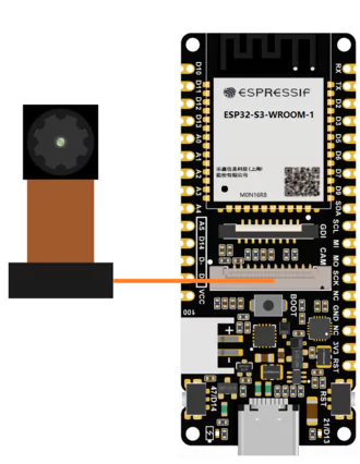


- Take the housing assembly and the cover assembly, carefully align the camera module cable with the corresponding connector on the ESP32 S3 board. Ensure that the connection is secure but do not force it if it does not fit easily.
- Press the housing and cover assemblies together until they snap into place. This will create a secure fit and keep the assembly intact during use.
- If the snap fit is not tight or feels loose, apply a small amount of super glue along the edges where the housing and cover meet.
Gluing Magnets


In this step, we will add magnets to both the housing and the mounting plate so that they can easily attach to each other for a secure and flexible mounting system.
- You’ll need 8 magnets for both the housing (the main body of the case) and the mounting plate (the clip).
- It’s crucial to keep the polarity of the magnets correct. Ensure that the magnets on the housing and the clip plate have opposite polarities, so they attract to each other.
- Apply a small amount of quick glue on the housing and the mounting plate where you plan to attach the magnets. Using tweezers, place the magnets carefully into the glue on each part. Ensure they are positioned flush.
- Once the glue has dried, bring the housing and mounting plate close together. They should attract and stick to each other securely. The magnets should hold the parts together but allow easy separation when needed. If the magnets aren’t aligned or the parts don’t stick, remove the magnets and try again with the correct polarity and alignment.
With the magnets securely in place, the case is now ready to be used with the SitSense posture system.
I have 3D Printed this extra Black mount for my other project use.
Uploading the Code




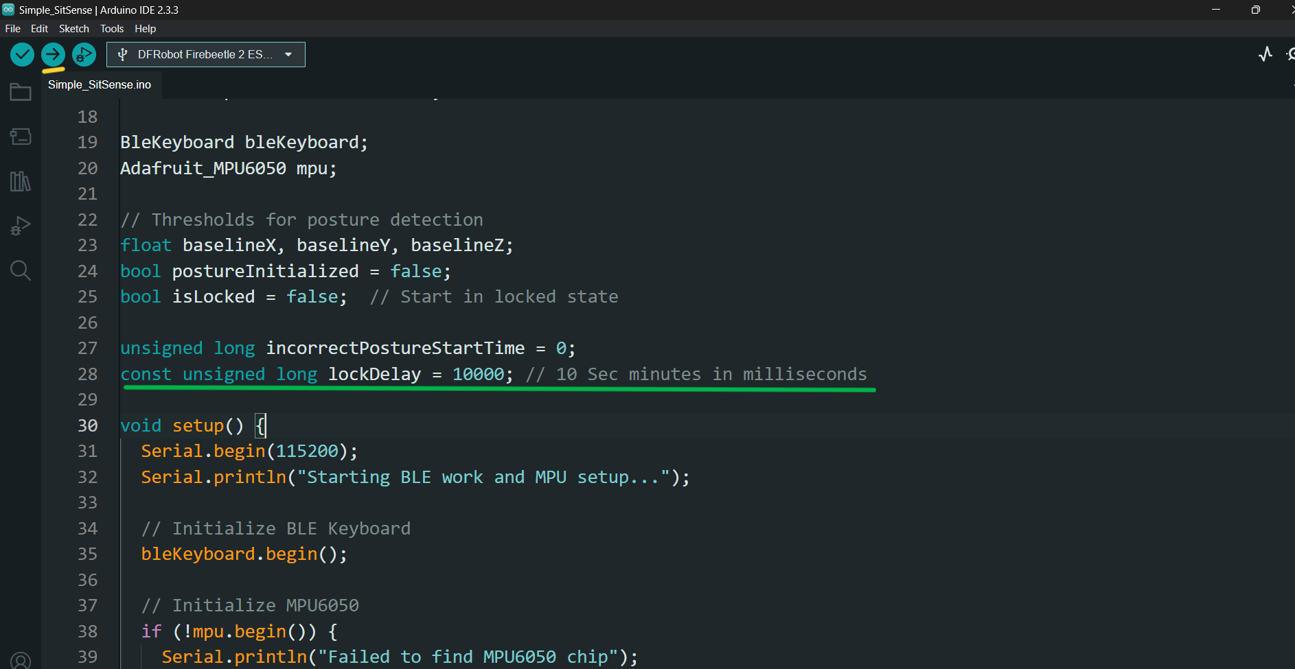


1. Download the Code
- GitHub Repository: Download the full repository
- Extract the files and locate the Simple_SitSense.ino file in the project folder.
- Open Arduino IDE on your computer.
- Navigate to File > Open, and select the Simple_SitSense.ino file from the extracted folder.
2. Install ESP32 Board Manager
If you haven’t already configured the ESP32 environment in Arduino IDE, follow this guide:
- Visit: Installing ESP32 Board in Arduino IDE.
- Add the ESP32 board URL in the Preferences window:
- Install the ESP32 board package via Tools > Board > Boards Manager.
3. Install Required Libraries
You need to install the following libraries for this project:
- ESP32_BLE_Keyboard Library
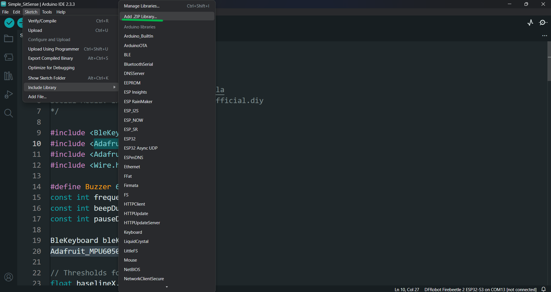
- In Arduino IDE, go to Sketch > Include Library > Add .ZIP Library and select the downloaded ESP32_BLE_Keyboard.zip file.
- Adafruit_MPU6050 Library
- Open the Library Manager: Tools > Manage Libraries.
- Search for Adafruit MPU6050 and click Install.
Go to Tools and set up the following:
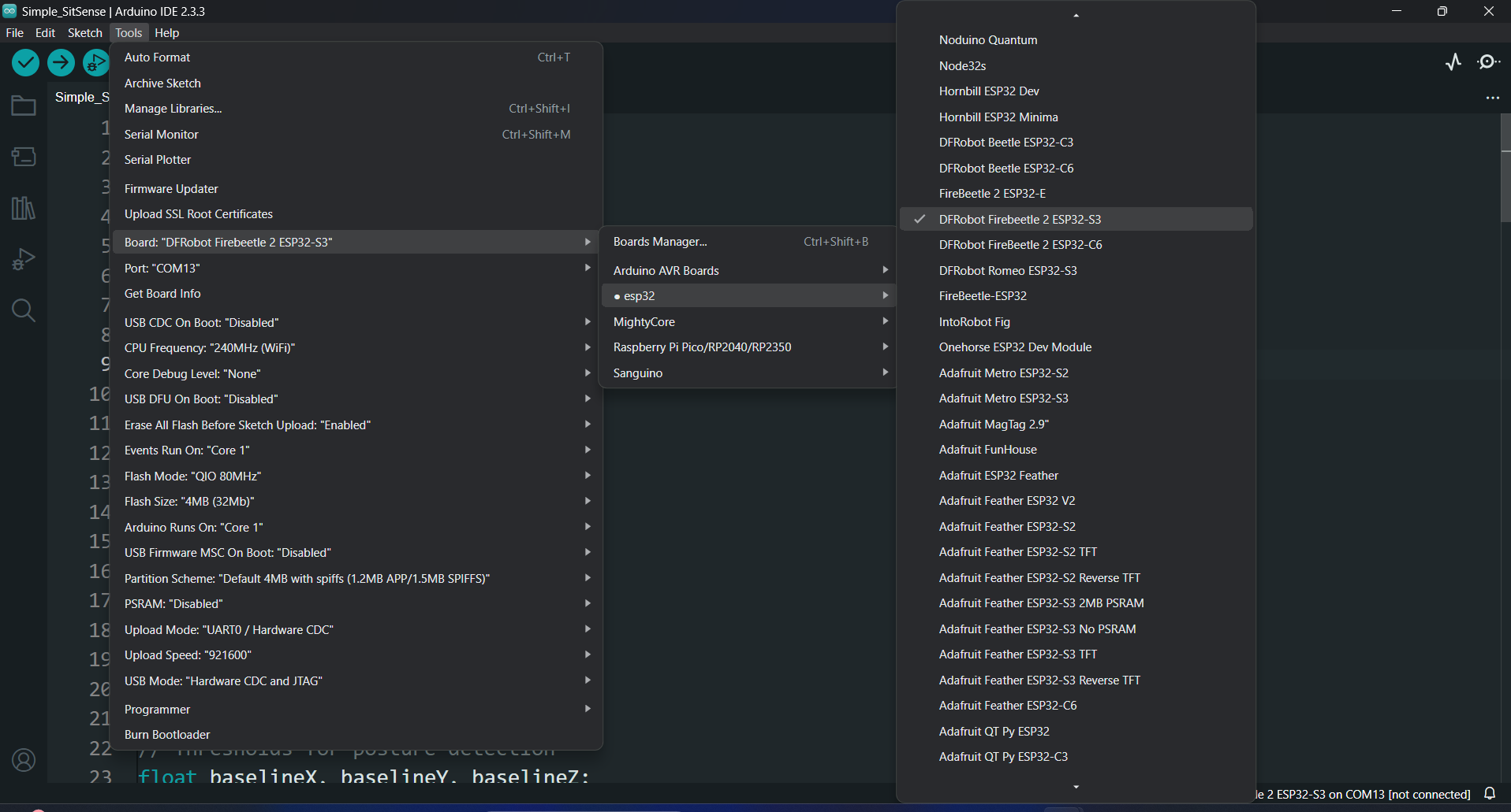
- Board: Select DFRobot FireBeetle 2 ESP32-S3 (or similar based on your exact board).
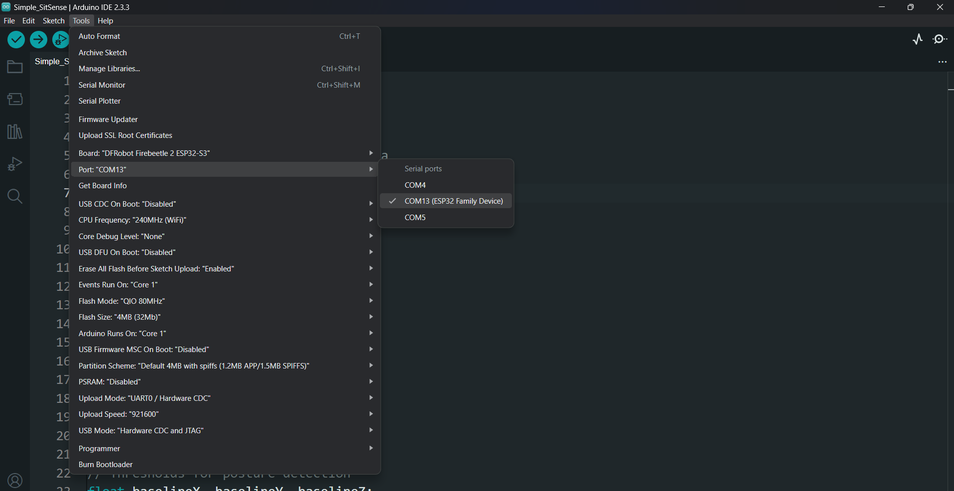
- Port: Select the COM port associated with your ESP32 board.
Click the Upload button (right arrow) in the Arduino IDE
With the code uploaded, your Simple SitSense device is ready! Here's how to get started:
Connect via Bluetooth
- Open the Bluetooth settings on your PC.
- Search for available devices, and you'll see your SitSense listed (as named in the code).
- Pair it just like you would with any other Bluetooth device.
Calibrate and Start Detecting Posture
- After pairing, SitSense will automatically calibrate to your initial posture at startup.
- Once calibrated, it will begin monitoring your posture and providing alerts if it detects any deviation from the calibrated position.
Recalibrating the Device
If you feel the calibration is off or not proper:
- Press the Reset button on the SitSense device.
- This will force it to recalibrate to your current posture.
- Once recalibrated, it should function correctly.
Simple SitSense Code Explaination


Key Features of the Code:
Calibration on Startup:
- At startup, the program calibrates to the current posture and assumes it as the "correct position" and connects to PC using Bluetooth.
Deviation Detection:
- If the posture deviates beyond the calibrated baseline, the buzzer will beep to notify the user.
Lock PC After Delay:
- If the bad posture is not corrected within 10 seconds (default), the system will lock the PC.
Change Lock Time:
- You can adjust the lock delay by editing the following line in the code at line 28:
const unsigned long lockDelay = 10000; // 10 seconds in milliseconds
Unlock Screen:
- After correcting posture, the system unlocks the PC by sending a pre-configured password through BLE (Bluetooth Low Energy) Keyboard functionality.
How to Configure the Password:
The password used to unlock your PC is defined in the function AT line no. 88:
Example code snippet to unlock using the password "1234":
If your password is different, replace KEY_NUM_1, KEY_NUM_2, etc., with the appropriate keys for your password.
Understanding HID (BLE Keyboard):
HID (Human Interface Device) is a protocol that allows devices like keyboards, mice, and game controllers to communicate with a host device (like a PC or smartphone).
In this project, we use BLE (Bluetooth Low Energy) Keyboard, which emulates a keyboard over Bluetooth. This allows the ESP32-S3 to send keypresses directly to your PC, enabling it to:
- Lock the Screen: By simulating the Win + L key combination.
- Unlock the Screen: By typing your password like a physical keyboard.
I am using BLE Keyboard Library from T-vK, use the same library if you are using the generic ESP32 board, the zip file which I provided is modified to work with ESP32 S3 and I have also tested it with ESP32 C6 as well.
The Simple SitSense code does a great job of getting the basics right, it assumes your initial position is the "Good Posture" and alerts you if it detects deviations. However, it has a major limitation: it treats every deviation as "Bad Posture." While functional, this approach is still a bit dumb.
Now, let's take this device to the next level and make it smart by integrating Edge Impulse! With this AI-powered model, SitSense can distinguish between multiple postures, good and bad, with much greater accuracy.
Installing & Setting Up Edge Impulse


To make SitSense smarter, we will use Edge Impulse, an AI platform designed to train and deploy machine learning models.
1. Install Edge Impulse CLI
The Edge Impulse CLI (Command Line Interface) allows us to connect the SitSense hardware to the Edge Impulse platform and collect posture data.
Follow the official Edge Impulse CLI Installation Guide to set up the required tools.
2. Create an Edge Impulse Account
- Visit Edge Impulse and create an account.
- Log in to access your project dashboard.
- Create the new project as shown in image.
Data Collection


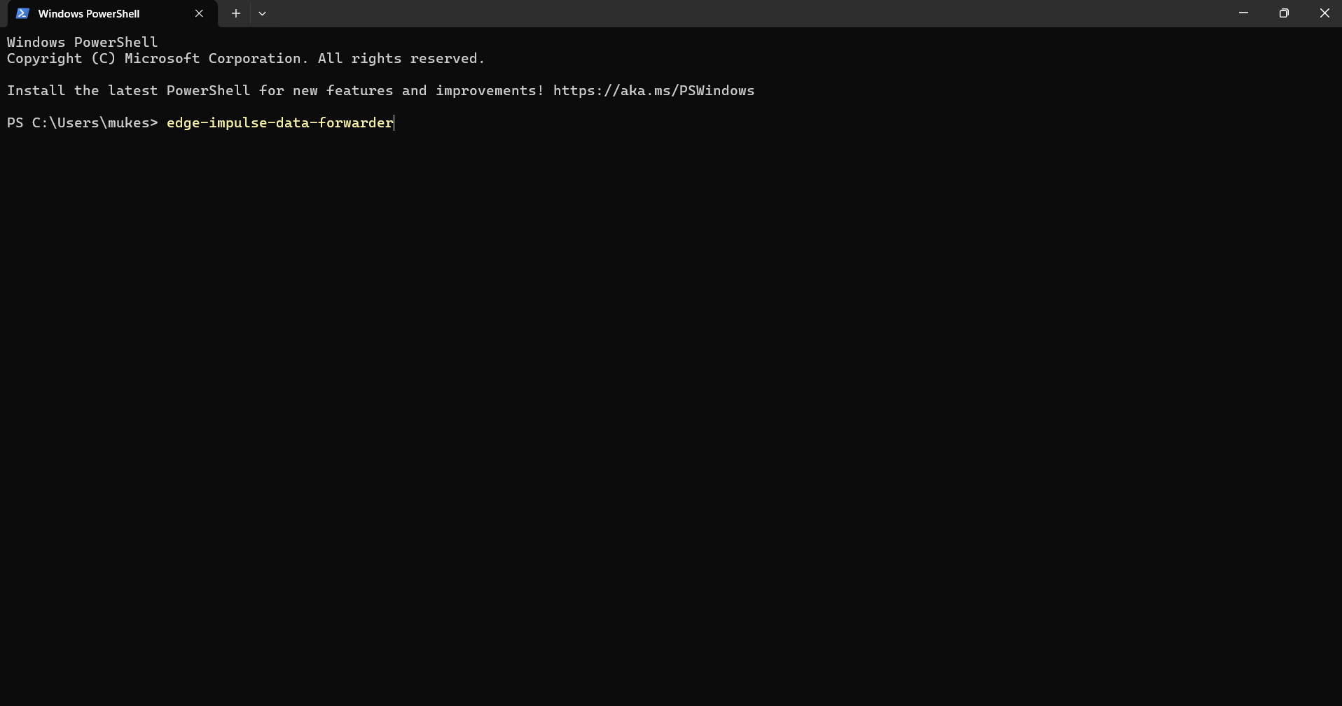


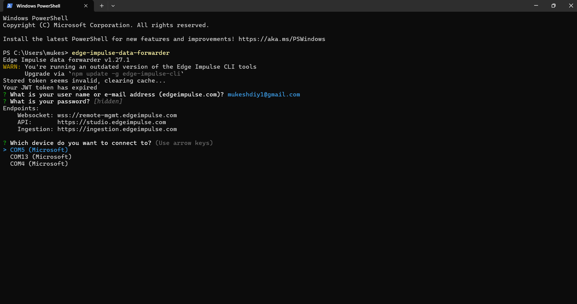

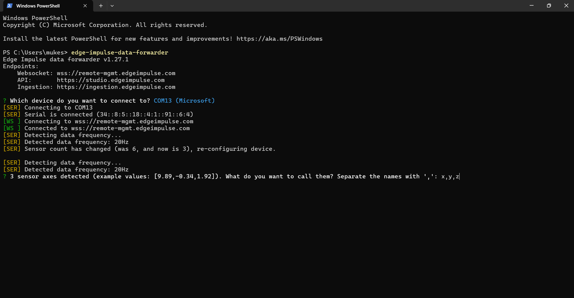
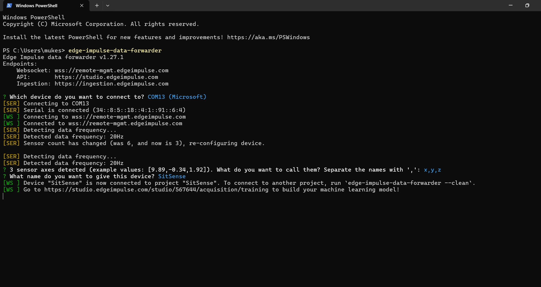


Now that the Edge Impulse CLI is set up and your project is ready, we’ll begin the most crucial part of creating a smart SitSense device: collecting data. This step helps train the AI model to distinguish between Good and Bad posture accurately.
Navigate to your project and open the Data Acquisition panel.
At this point, you should see an empty list of data samples and no connected devices.
1. Upload the Data_Collect Code to SitSense
- Open the provided Data_Collect.ino file in the Arduino IDE.
- Upload the code to your ESP32-S3 device following the same steps as in previous uploads.
This code enables SitSense to send accelerometer data (X, Y, Z values) to Edge Impulse for collection.
2. Use Edge Impulse Data Forwarder
- Open a command line/terminal.
- Type the following command:
- Log in using your Edge Impulse account credentials when prompted.
3. Connect SitSense to Edge Impulse
- Ensure SitSense is connected to your PC via USB and mount the SitSense on your body using the magnetic clip.
- Select the correct port from the list displayed in the CLI.
- The CLI will prompt you to name the sensor data streams:
- Enter x, y, z for accelerometer data.
- It will also ask for a device name:
- Enter SitSense (or any name of your choice).
4. Register the Device on Edge Impulse
- Keep the CLI running.
- Go back to your Edge Impulse project’s Data Acquisition panel.
- You should now see your device (SitSense) listed and ready for data collection.
5. Start Collecting Data
- Set the Sampling Length to 1000 ms (1 second) in the Data Acquisition panel.
- Click Start Sampling.
- SitSense will now start forwarding accelerometer data to Edge Impulse.
7. Label Your Data
- Record data for both Good Posture and Bad Posture:
- Good Posture: Sit with your back straight and shoulders aligned.
- Bad Posture: Slouch or hunch over.
- Label each sample accordingly as Good or Bad in the Data Acquisition panel.
8. Collect Enough Samples
- Aim to collect 100+ data samples for both Good and Bad posture.
- Ensure variability in the postures to improve model accuracy.
- Example: Slightly tilt your head, lean slightly forward, or slouch deeper for "Bad" posture samples.
- Split your data into:
- Training Set: 80% of your data.
- Test Set: 20% of your data.
9. Add More Data for Better Accuracy
The more data you collect, the better your model will perform. Spend extra time collecting diverse posture data to make SitSense robust and reliable.
Once data collection is complete, you're ready to move on to training the AI model.
Note: Use Edge Impulse Official Documentation in case of any doubt or issue.
Creating the Impulse and Raw Data Features


In this step, we will define the machine learning pipeline, called an Impulse, and generate features from the collected data.
1. Creating the Impulse
- Open the "Create Impulse" panel in Edge Impulse.
- Add the Processing Block as "Raw Data."
- Add the Learning Block as "Classification."
- Save the impulse.
An Impulse is essentially the flow of data from its raw state to the trained machine learning model. By selecting "Raw Data," we are allowing the model to use accelerometer data directly without additional preprocessing. The "Classification" block is used to differentiate between the two classes, Good and Bad posture.
2. Generate Features
- Navigate to the Raw Data panel in your Edge Impulse project.
- Click the Generate Features button.
- The system will process all the data collected (Good and Bad posture) and generate feature maps. This step visualizes the difference between the two classes based on the input data.
Visualizing Data
- Feature map shows how well-separated the two classes (Good and Bad posture) are. In our case, the Good posture points are grouped together (orange), while Bad posture points form a separate cluster (blue).
- A clear separation indicates that the model will perform well in classification.
Once you've confirmed the feature generation and explored the data, you're ready to move on to training the model!
Classifier & Training the Model

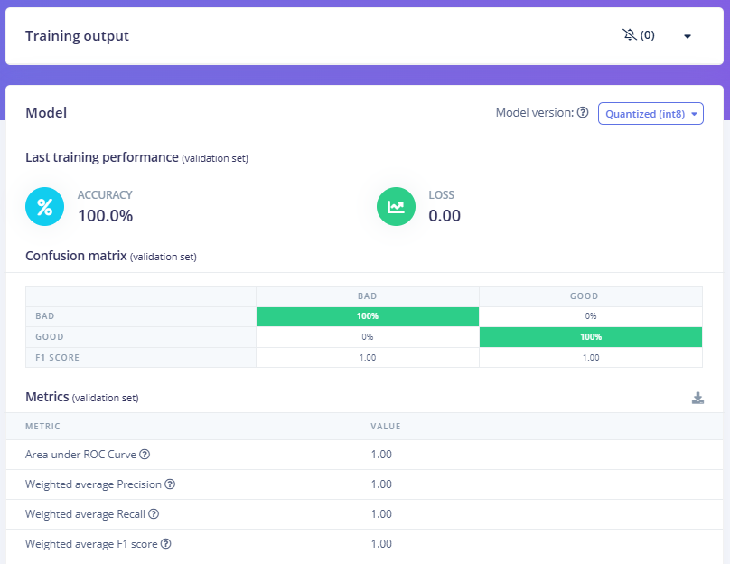

Now that we have set up the impulse and generated features, it's time to train the classifier to recognize Good and Bad postures.
1. Navigate to Classifier Panel
- Here, you will define how the model learns to distinguish between Good and Bad postures using the data you've collected.
2. Set Training Parameters
- Feature Processing: Ensure that the data processing from the impulse setup is reflected here.
- Training Parameters: Default settings usually work well. You can fine-tune later if required:
- Epochs: 30
- Learning Rate: 0.005
- Validation Split: 20% (ensures the model tests itself on unseen data).
3. Train the Model
- Click the Save & Train button. This process may take a few minutes, depending on the amount of data.
- Once the training is complete, you will see the performance metrics:
- Accuracy: Ideally, aim for 95% or higher for posture detection. In our case, it reached 100% accuracy.
- Loss: Lower is better, and here it is 0.00, which is excellent.
- Confusion Matrix: Shows how well the model classified the training and validation data:
- 100% of Good posture labeled correctly.
- 100% of Bad posture labeled correctly.
4. Performance Metrics
- Validation metrics show a weighted precision, recall, and F1 score of 1.00, confirming no misclassification during testing.
- Training accuracy is 100%, showing perfect differentiation between Good and Bad posture.
Your model is now trained and ready to be deployed!
Deployment


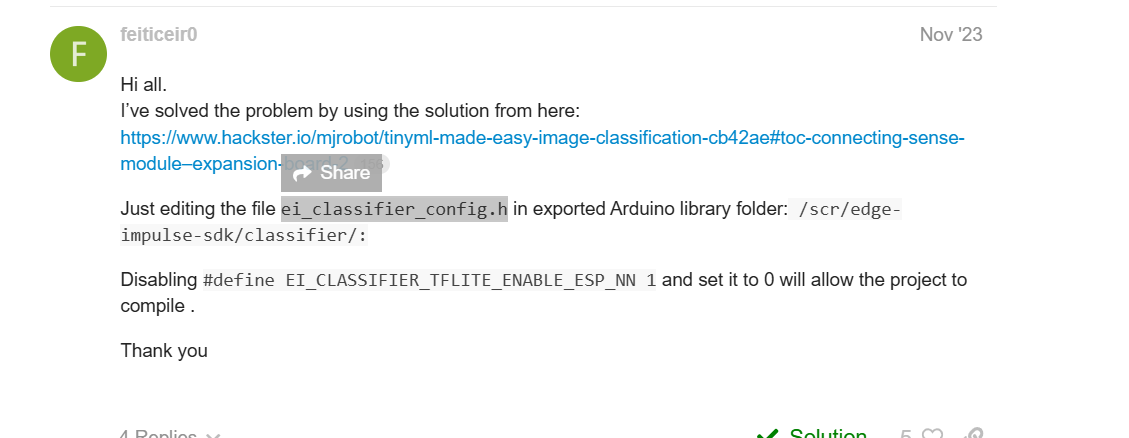

Once your model is trained, it's time to deploy it to the SitSense device for real-time posture detection. The deployment process involves creating an Arduino-compatible library from your trained Edge Impulse model.
1. Generate the Deployment Files
- Navigate to the Deployment tab in your Edge Impulse project.
- Under the deployment options, select Arduino Library.
- Make sure the Quantized (int8) option is selected (this ensures the model is optimized for the ESP32).
- Click Build to generate the library.
- After the build completes, download the generated .zip file for the Arduino library.
- In Arduino IDE, go to Sketch > Include Library > Add .ZIP Library and select the downloaded zip file.
2. Modify the ei_classifier_config.h File
- Navigate to the ei_classifier_config.h file inside the extracted library folder:
- Path:
- Documents\Arduino\libraries\SitSense_inferencing\src\edge-impulse-sdk\classifier\ei_classifier_config.h
- Open this file in a text editor (like Notepad or VS Code).
- Find the following line:
- Change it from 1 to 0:
Why this change?
- This setting disables the ESP-NN (Neural Network acceleration) for TensorFlow Lite, which can sometimes cause issues with certain models on the ESP32. Disabling it helps ensure the model runs properly.
- Save the file after making this change.
Upload the Code
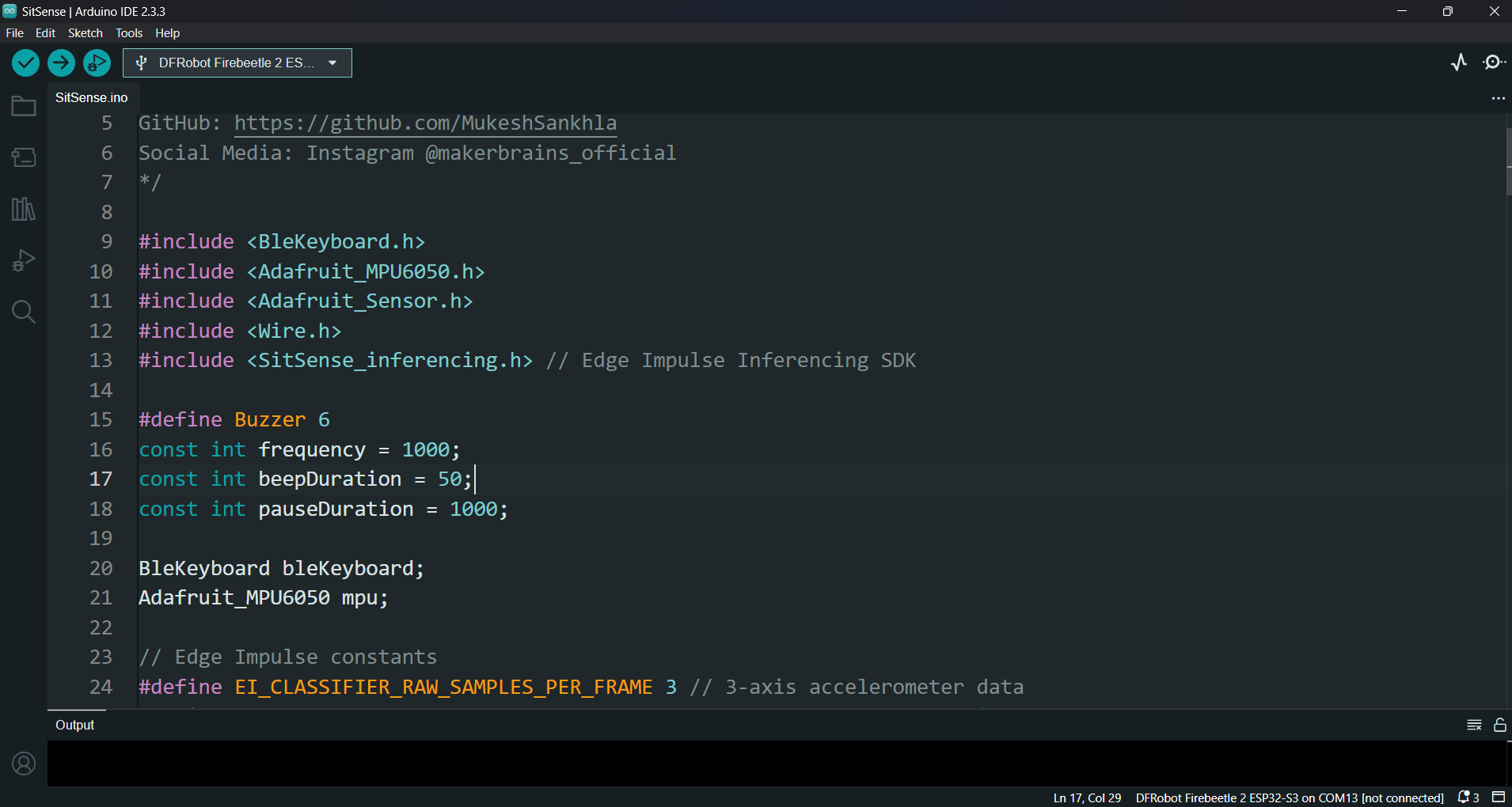
Now that you have everything ready, let's go through the final steps to upload the code and get your SitSense device working with your Edge Impulse model.
1. Setup the Arduino Code:
- Open the SitSense.ino file in your Arduino IDE.
- This file contains the code to connect your ESP32, collect accelerometer data from the MPU6050, and run inference using the Edge Impulse model.
Here's a brief overview of the important sections in the code:
- Libraries:
- The code uses the following libraries:
- BleKeyboard: For simulating keyboard input to lock/unlock the PC.
- Adafruit_MPU6050 and Adafruit_Sensor: For accessing the MPU6050 sensor.
- SitSense_inferencing: For running the Edge Impulse model (you'll need to replace this if you are using your custom model).
- Edge Impulse Constants:
- EI_CLASSIFIER_RAW_SAMPLES_PER_FRAME: Number of samples per frame (usually 3-axis accelerometer data).
- EI_CLASSIFIER_RAW_SAMPLE_COUNT: Number of samples to collect before running inference.
- Inference Function:
- The classify_posture() function takes accelerometer data and uses the Edge Impulse model to classify the posture as either "Good" or "Bad".
- Lock and Unlock PC:
- If "Bad posture" is detected, the screen is locked using the lockScreen() function by sending a Windows Win + L keypress.
- If the posture is corrected, the PC is unlocked using the unlockScreen() function by entering the PIN.
2. Update the Code (For Custom Model):
If you are deploying your own Edge Impulse model, you need to ensure that the correct model is linked in the code.
Find this line in the code:
If you're using your custom model, ensure the path to the model header file is correct. For example, if you deployed your own model and it's located under the folder SitSense_inferencing, make sure this line corresponds to the correct path in your Arduino library folder:
3. Upload the Code:
- Select the correct board (DFRobot FireBeetle 2 ESP32-S3) in the Tools menu of the Arduino IDE.
- Select the correct Port for your device.
- Click Upload to flash the code to your ESP32.
4. Test the Device:
Once the code is uploaded:
- The SitSense device will now be collecting accelerometer data and classifying posture using the Edge Impulse model.
- If the posture is "Bad," the device will emit a beep sound (using the buzzer) and may lock the PC.
- If the posture is "Good," the device will stop the buzzer and unlock the PC if it was previously locked.
Conclusion


And that's it! SitSense is not just a fun project, it’s an incredible fusion of technology and innovation that teaches us valuable lessons in electronics, IoT, HID (Human Interface Devices), and Edge Impulse. By working with this project, we’ve explored how AI models can be integrated into real-world applications to solve practical problems, like improving posture and enhancing productivity.
But what makes SitSense stand out is the power of simplicity. We used the versatile ESP32-S3 to create a highly portable and wireless posture detection system. Thanks to its powerful capabilities, including Bluetooth connectivity and its small form factor, SitSense is as effective as it is convenient. The magnetic design of the device makes it easy to attach anywhere without worrying about complicated mounting systems, while the battery portability ensures you can use it on the go for extended periods.
Wireless freedom, combined with the lightweight design and efficiency of the ESP32-S3, enables endless possibilities for future projects. Whether you’re making a more advanced version of SitSense or venturing into other IoT and AI-driven solutions, the versatility of this device is your gateway to an entire universe of innovation.
As you explore new horizons with Edge Impulse, the powerful AI models, and the cutting-edge capabilities of the ESP32-S3, there are countless more projects to create and share. I encourage you to use the codes, 3D designs, and ideas shared in this project to push the boundaries of what you can achieve.
Thank you for joining me on this journey. If you enjoyed this project, please don’t forget to like, comment, and share your own experiences in the "I Made It" section. The future is filled with endless potential, and I’m excited to see what amazing projects you’ll create with this incredible technology.
See you next time, and happy making ;)