Slot Machine Game

This project is a recreation of the traditional slot machine games, it uses the gen4-uLCD-70DCT-CLB as a display interface where you can press the buttons to start or stop the game.
Users are also encouraged to improve the project by connecting the project together with other peripheral devices such as coin acceptor modules and crank switches to recreate the whole slot machine experience.
How It Works

This project is controlled by buttons to stop columns and compare the result to state if you win or lose.
Components


- gen4-uLCD70DCT-CLB
- gen4-PA or gen4-IB
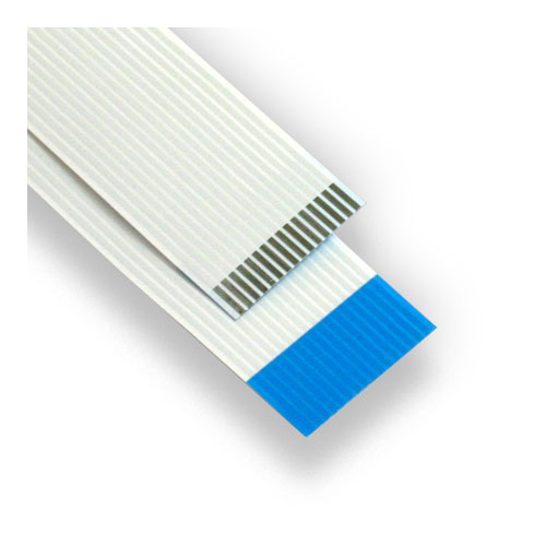
- FFC cable
- uSD card
- uUSB cable
Build


*If you are using gen4-IB and μUSB PA-5, connect the display to your computer as shown in the second image.
*If you are using gen4-PA board,connect the display to your computer as shown in the third image above.
Download the project file here.
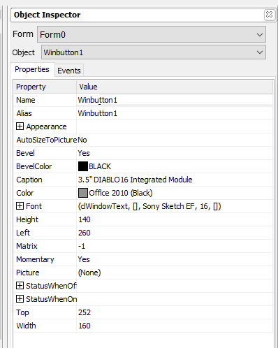
You can download Workshop 4 IDE and the complete code for this project from our website.Open the project using Workshop 4. This project uses the ViSi Environment.You can modify the properties of each widget. (Image4)
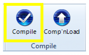
Click on the Compile button. (This step could be skipped. However, compiling is essential for debugging purposes.) (Image5)
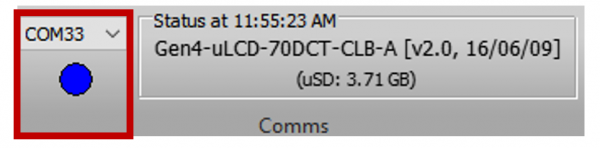
Connect the display to the PC using μUSB-PA5 and a mini USB cable. Make sure that you are connected to the right port. Red Button indicates that the device is not connected, Blue Button indicates that the device is connected to the right port.(Image6)
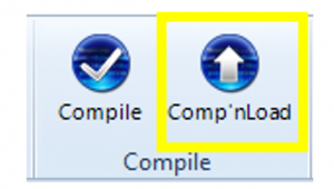
Now click on the “Comp’nLoad” button. (Image7)
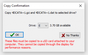
Workshop 4 will prompt you to select a drive to copy the image files to a μSD Card. After selecting the correct drive, click OK. (Image8)
Demonstration
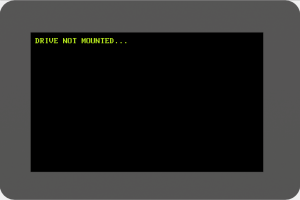

The module will prompt you to insert the μSD card. (Shown in first image)
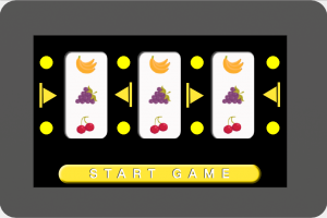
Properly unmount the μSD Card from the PC and insert it to the μSD Card slot of the display module. The image above must appear on your display after completing the steps.