Small Hand Held Counter - With Arduino ESP32C3 Super Mini
by sncarter in Circuits > Arduino
607 Views, 1 Favorites, 0 Comments
Small Hand Held Counter - With Arduino ESP32C3 Super Mini
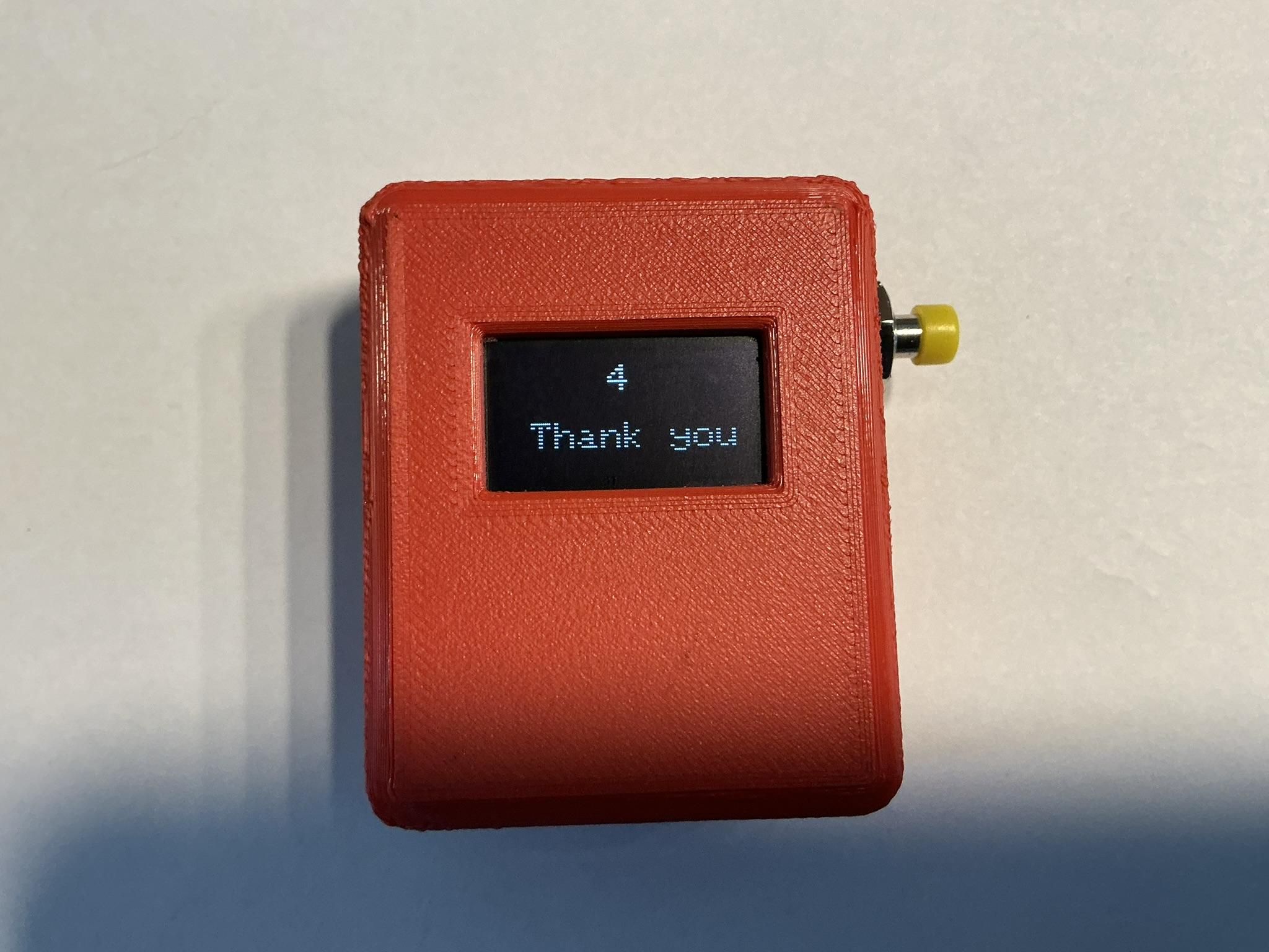
This is a small (1.8" x 2.2") Handheld counter which uses the Arduino code in the ESP32CS Super mini board.
There is a theory that if you develop an "attitude of gratitude" that your life will change for the better. Some spiritual leaders suggest that if you say "Thank You" lots of times this moves you along that path. So I have configured this counter as a little gratitude counter. You can easily change the code to display counting anything you like. Every time you are thankful for something you can press the button and count your thank you. How many can you do in say a month, I wonder? Let's find out!
Supplies
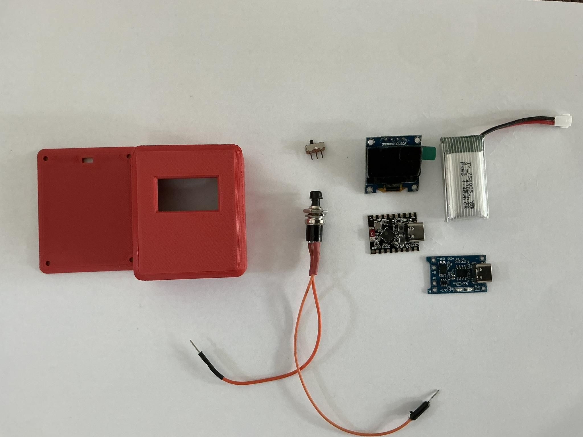
For this project, you will need the following:
1 - SSD1306 128 x 64 OLED display module SSD1306 OLED Display
1- ESP32C3 (Or equivalent processor) module ESP32-C3 Mini
1 - TP4056 Lithium Battery Charger TP4056 Micro-USB 5V 1A 18650 Lithium Battery Charger Module Charging Board
1- Flat Pack 3.7V lithium battery (400ma) 3.7V 400mAh High Rate Lithium Battery
1 - Small Pushbutton Switch
1 - Small sliding switch
3 - 10k resistors
3 - 4.7k resistors
1 - 100uf capacitor
1 - small piece of prototyping perfboard
4 - small screws about 1/2" long
#30 AWG wire wrap wire or equivalent small guage wire
Hot glue and hot glue gun
Solder and soldering iron
3D Printer and filament
The Circuit
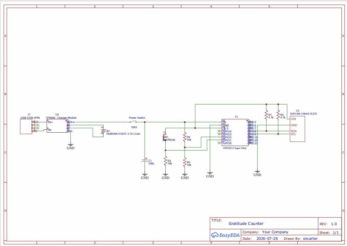
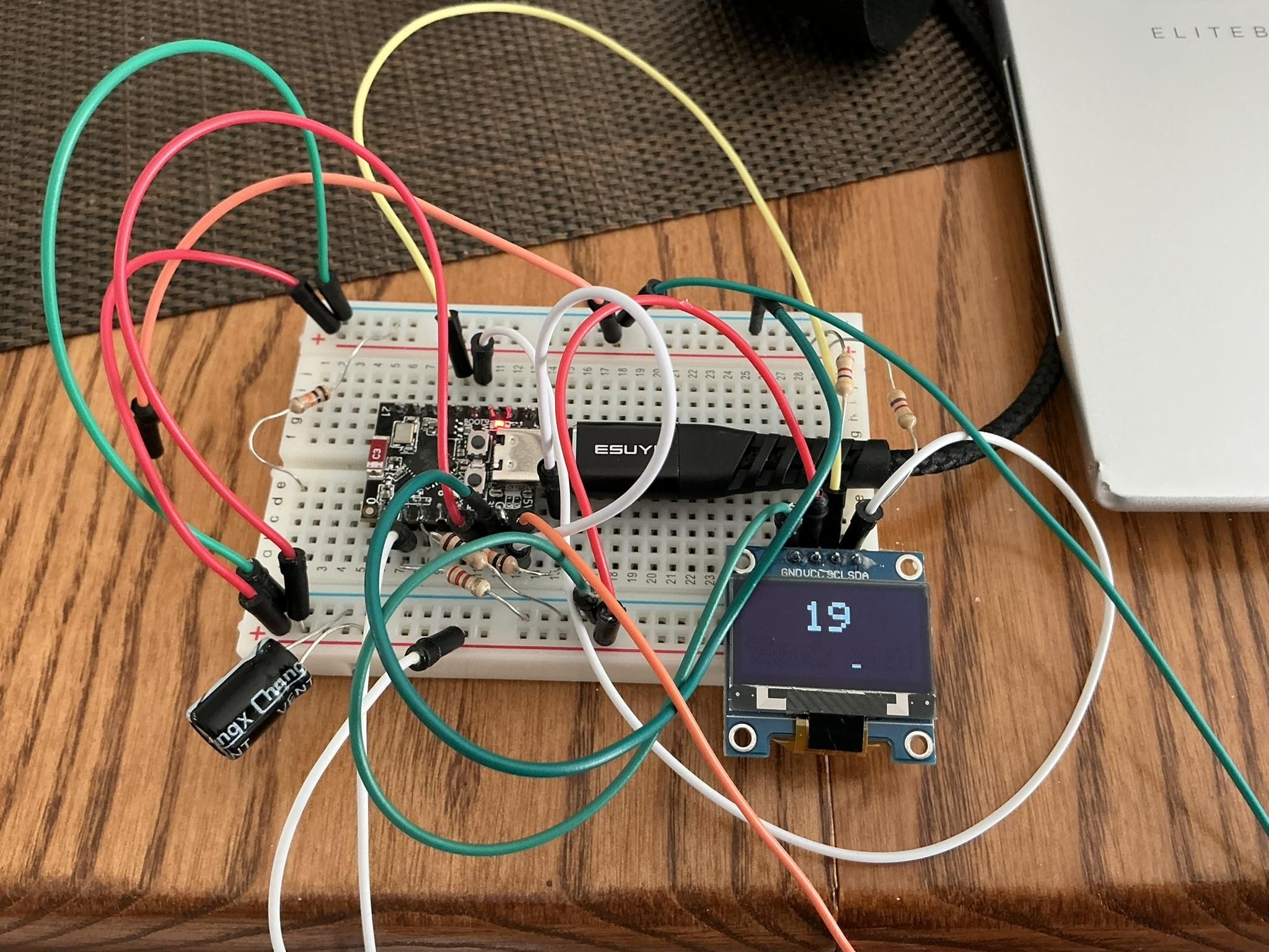
To start, I'd strongly suggest that you try this out on a breadboard first and make sure you get all the wiring right and the code loaded. It will be much easier to trouble shoot any issues you encounter if you do this first.
The circuit is based around the ESP32C3 processor board. The TP4506 charges the lithium battery and it's USB-C port is inserted into the USB-C hole in the case. I placed the power switch between the TP4506 output and the rest of the circuit. You could also place it between the battery and the TP4506, but then you would need to have it switched on to charge, your choice really on how you'd like that.
The ESP32C3 GPIO pins are not 5V tolerant, they work on 3.3V only. So you can connect the 5V in pin on the ESP32C3 to the battery, but ONLY that pin and not any of the other pins. So we will use the 3.3V out pin on the ESP32C3 for powering most of the circuit.
C1 - 100uf is used to stabilize power and slow down the voltage drop when power is shut off or low, this gives the processor time to record the last count in a low voltage power loss condition.
R4 and R5 form a voltage divider to sample the battery voltage. In the code we then use math to calculate the true battery voltage based on the sample which will be half the battery voltage. We do this because we cannot connect more than 3.3V to the GPIO pin. We also do this because for this processor's ADC pins, 2.5V is full scale represented by a digital ADC reading of 4096 for the 12 bit ADC. Applying more than 2.5V is not recommended as the ADC value returned will be wildly inaccurate. It is also noted in literature that this processor's full scale value even at 2.5V is not that accurate and may actually be full scale at up to 2.7V. So accuracy is only moderate.
R3 pulls the pin connected to the pushbutton switch decisively to low unless the switch is pressed.
R1 and R2 are pull up resistors required for the I2C SDA and SCL pins. It will quite often work without these, but sometimes not, so best to have them in place.
Again note that everything other than the battery connection to the processor's 5V pin is connected only to 3.3V max.
The Arduino Code
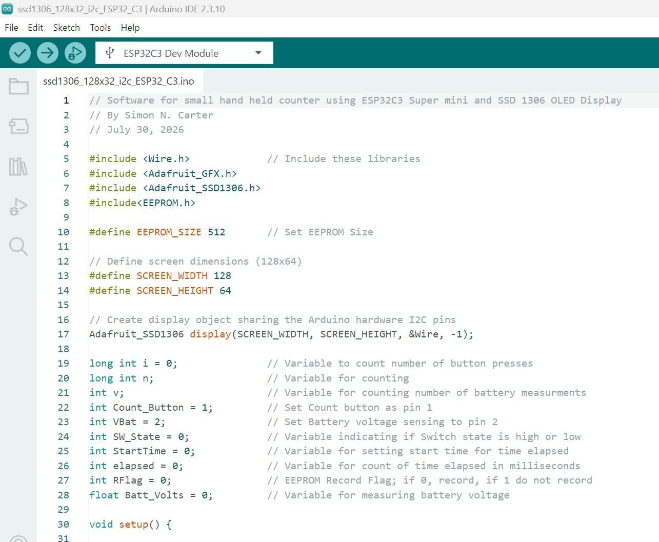
The Code is fully commented, you should be able to follow how it works from this.
Downloads
3D Printing
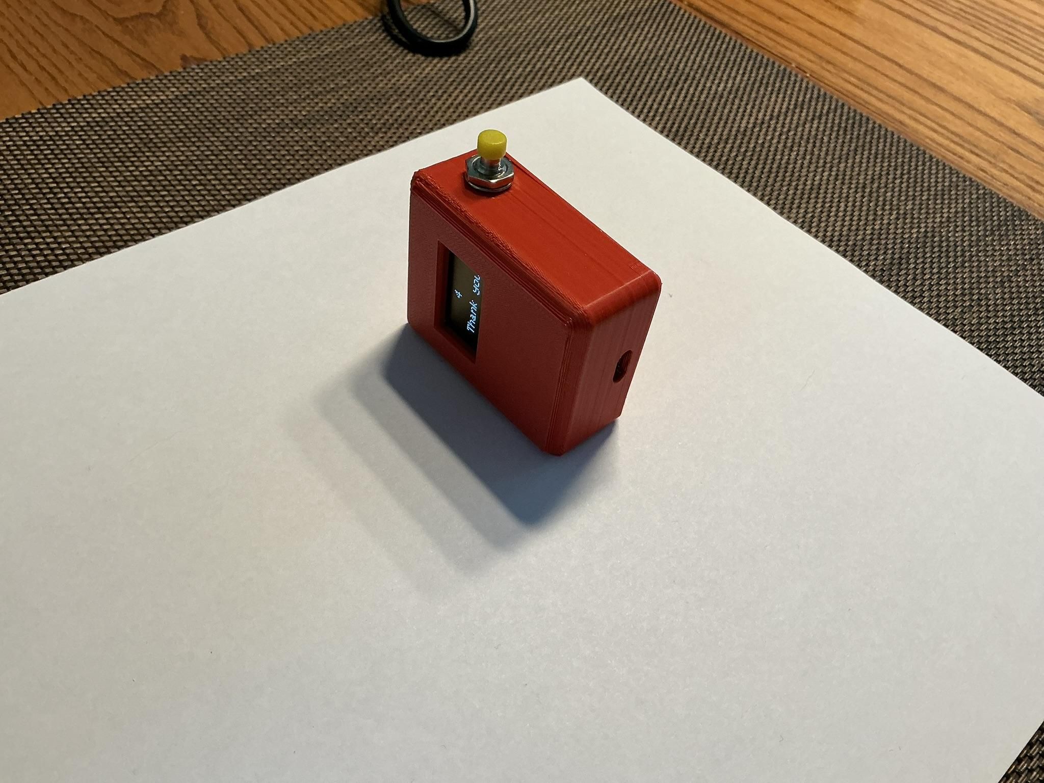
The case was designed using OnShape. Excellent software and easy to use. I have attached Gcode and STL files if you want to use them or modify them.
Final Assembly
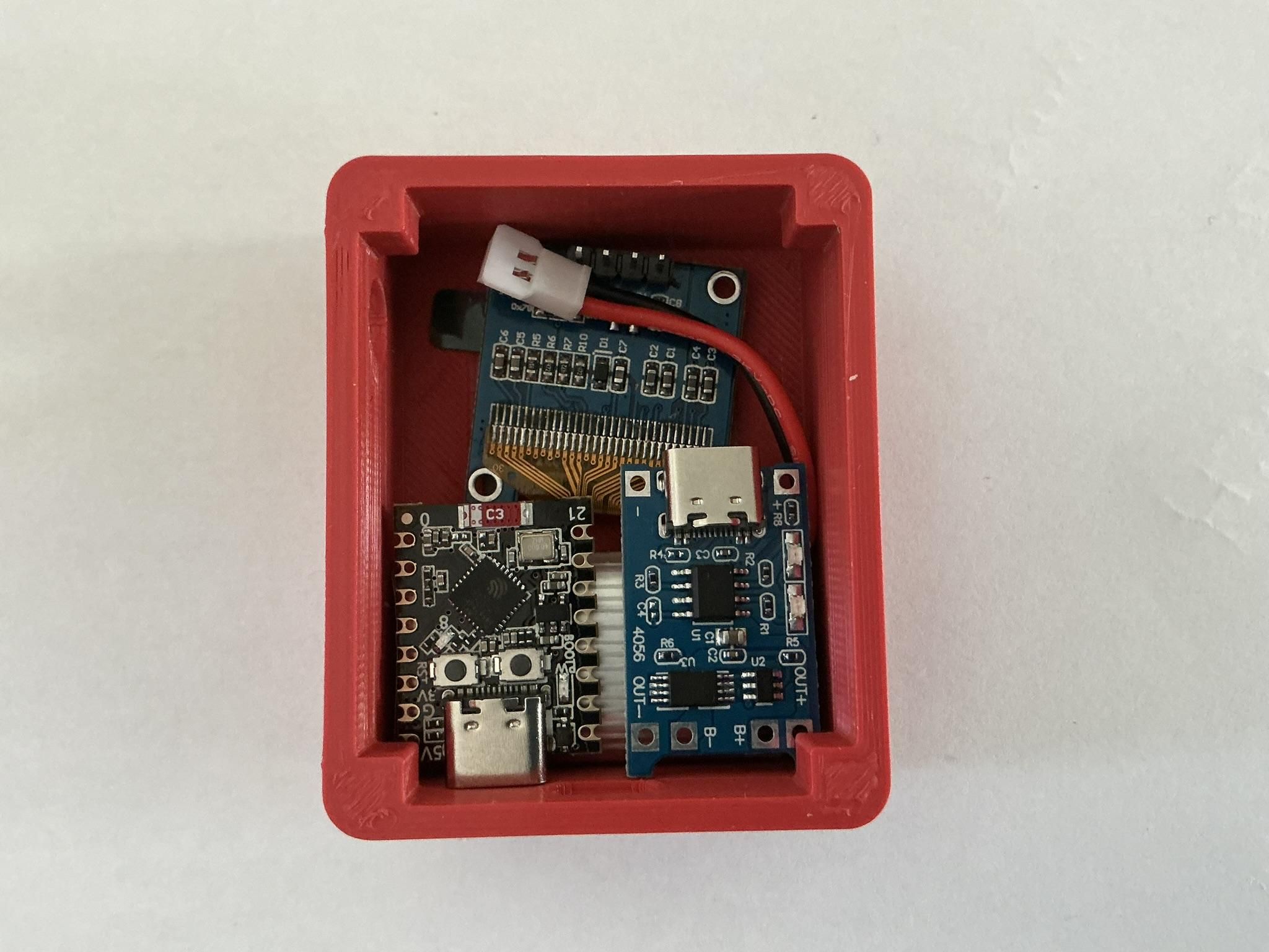
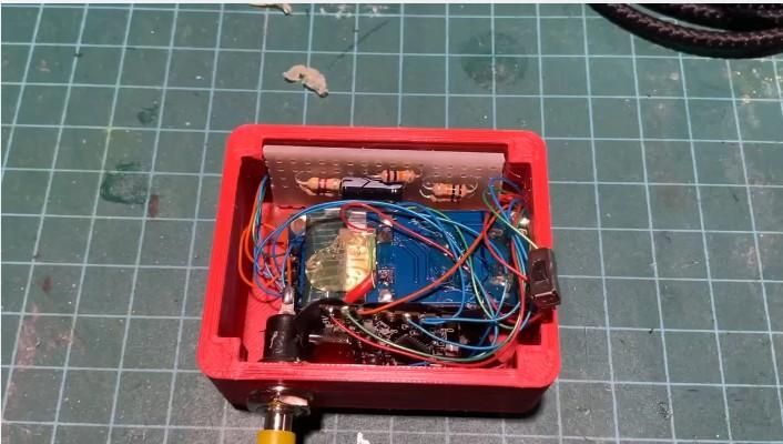
Inserting the parts in the box is fairly adhoc. First wire everything together as per the schematic using the #30 AWG wire (See how I did this in the video). Wire up the battery last.
Next, install the OLED screen in the case first and hot glue it in place. Next the small perf board with resistors and capacitor. Cut this to a size that allows you to install it vertically along the long inside edge of the case. Component side facing the center of the box. Next put in the battery and then place the TP4506 in place above it and hot glue in place. Next, place the processor in vertically on the opposite side to the perf board. Be sure to wrap some insulating electrical tape on the side that faces inward for electrical isolation. Last hot glue the small sliding switch in place and screw on the lid.