Smart Alarm Clock - There's No Way You Won't Wake Up After It
by Guy Laor in Circuits > Arduino
173 Views, 0 Favorites, 0 Comments
Smart Alarm Clock - There's No Way You Won't Wake Up After It


Suffering from problems waking up in the morning?
Confused about what to wear and don't know what the weather is like?
Get ready for the smart alarm clock interface you've always dreamed of!
By developing in Arduino to ESP32 using Adafruit IO, you will get a smart alarm clock interface.
You can set when the clock will ring, like any classic clock, or you can trust a friend and send him a link to a switch so he can start the alarm remotely ;)
No more turning off the alarm while sleeping and then falling back to sleep.
To turn off the smart alarm clock, you'll have to prove to it that you actually woke up!
How will you do it? By turning on the light in the room (or opening the window, the main thing is that light illuminates the darkness :)) and simultaneously pressing three touch sensors.
We'll see you do it in your sleep!
Who hasn't encountered the familiar problem of having to adjust clothes to the weather outside, without knowing what the appropriate weather is?
Most of the time we tend to dress according to the weather that prevails in our room, a situation that may cost us dearly in case the weather turns out to be especially different outside.
In the dashboard of the smart alarm clock, you will always see a temperature gauge and a hygrometer. Each of them will have two instances - the first, data received from a sensor connected to the ESP32 and representing the data in your room or where you are. The second, official data obtained from openweathermap and representing the official weather where you live. This way you can make the adjustment between the perceived weather in your room and the real one. A red light will light up along with the alarm clock. You can turn off the light, again, by proving that you have dressed according to the appropriate weather. First, you will have to mark with a thermometer the correct temperature according to which you should dress (remember there are two temperature gauges?). Second, you will have to mark with a switch that you have finished dressing accordingly.
Both of these actions will turn off the red light.
After all that, you are undoubtedly ready to start your day!
Ready to find out how you can have such a smart alarm clock?
Supplies


Softwares:
- Arduino - IDE
- Internet connection
physical components:
- computer
- ESP32 controller + PC connection cable
- Expansion board for connecting components and sensors to the controller
- Cables for connecting components to the expansion board of the controller
- Temperature and humidity sensor
- Three touch sensors (in our example: wires connected to the expansion board on one side and conductive foil on the other)
- light sensor
- blink output component to display a light bulb
- Output component for playing sound
Setup
- Installing Development Environment
- Installing Download Arduino IDE (the desktop version) using the following link: https://www.arduino.cc/en/Main/Software
- Desktop version only
- Download and install board communication driver: https://www.silabs.com/developers/usb-to-uart-bridge-vcp-drivers?tab=downloads
- Install ESP32 Board Manager: https://www.youtube.com/watch?v=mBaS3YnqDaU&t=11s
- Restart Arduino Software
- Connect the board to a USB port
- Defining the Work Environment
- Choose the port
- Tools -> Port -> COMXXX (Mark the port that was added when you connect the controller to the computer)
- Choose the board
- Tools -> Board -> ESP32 Arduino -> ESP32 Dev Module
- Importing external libraries for the benefit of running the code
- Make sure you have the following libraries in your workspace
- WiFi.h
- PubSubClient.h
- DHT.h
- DHT_U.h
- HTTPClient.h
- ArduinoJson.h
- Some are public and you can use them directly. For your convenience, the files of some of the libraries are also attached here:
- Creating an account in relevant services
- Create an account in openweathermap
- Create an account in Adafruit IO
Create Your Adafruit IO Working Environment


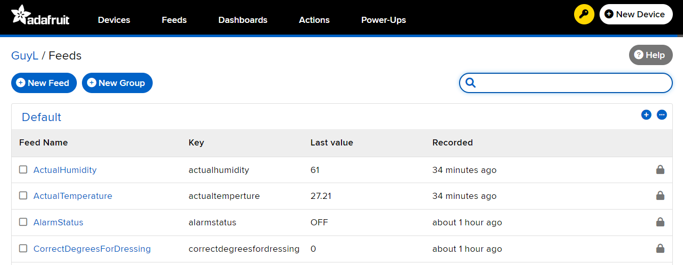
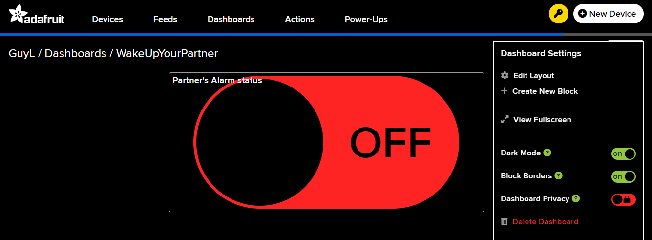
In this step we will create the required working environment in Adafruit IO. Feel free to go deeper and read more about the platform
- Creating Feeds
- Go to the Feeds tab (a picture is attached) and create the following feeds:
- ActualHumidity
- ActualTemperature
- AlarmStatus
- CorrectDegreesForDressing
- DressStatus
- LightStatus
- RoomHumidity
- RoomTemperature
- Creating Dashboards
- Go to the Dashboards tab (a picture is attached) and create the following dashboards:
- WakeUpYourPartner
- Add one Block of toggle button type which is connected to the Feed AlarmStatus. The default parameters are sufficient (a picture is attached)
- MySmartAlarm
- Add the following blocks:
- Simple on/off indicator lamp - connected to AlarmStatus, Conditions: = ON
- Simple on/off indicator lamp - connected to LightStatus, Conditions: = LIGHT
- gauge - connected to RoomTemperature
- gauge - connected to RoomHumidity
- gauge - connected to ActualTemperature
- gauge - connected to ActualHumidity
- slider - connected to CorrectDegreesForDressing, Slider Step Size: 1
- toggle button - connected to DressStatus, Button On Value: DONE, Button Off Value: DOIT
! Note that the design of the dashboard, the names of the blocks, and the exact values in each of them, which affect and are also affected by the code running on the ESP32, can be changed at your choice
Arduino -> Code -> ESP32
- Connect all components to the expansion board so that they are connected to the controller according to their definitions in the code. Of course, this value can be changed according to your connections
- Connect the controller to the computer
- Open the attached code using the Arduino Integrated Development Environment (IDE) on your computer
- Edit in the code the parts required for local execution (note that there are many variables that are optional to change, such as in the case that you have chosen different Feed names, etc. We will focus on the critical variables to edit)
- Wi-Fi network details
const char* ssid = "your_network_name"; // Change to your Wifi network name
const char* password = "12345678"; // Change to your Wifi password
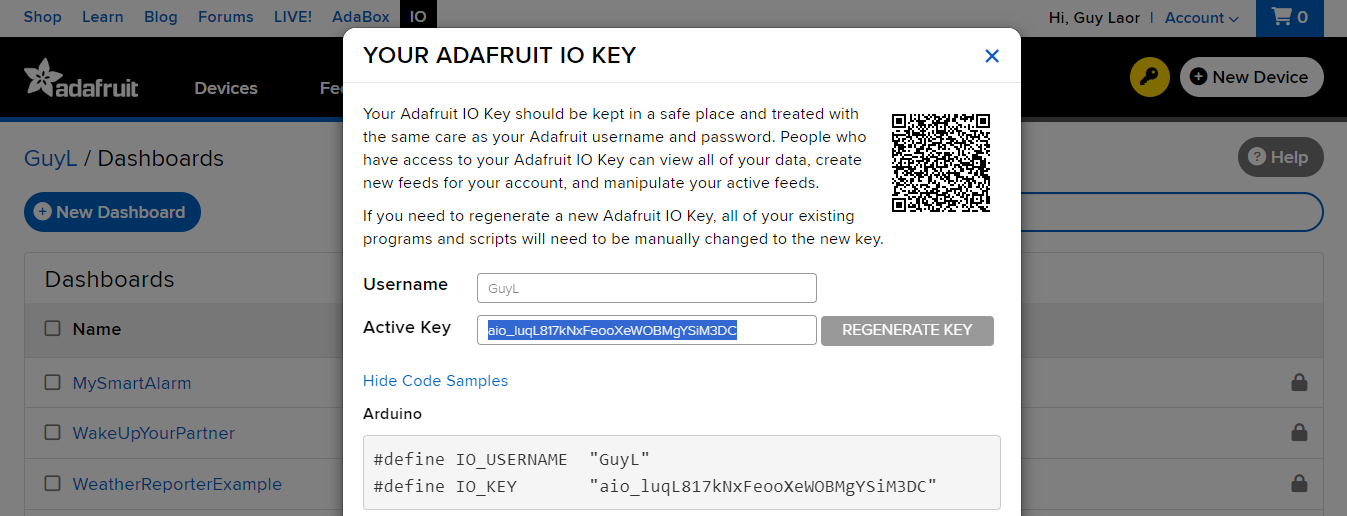
- MQTT server login details. You can find your login information by clicking on the key on the yellow background on the right side of Adafruit IO screen (a picture is attached)
const char* mqtt_username = "userName"; // Change to your IO username
const char* mqtt_password = "aio_abcabcabc"; // // Change to your IO key
- openweathermap and location details
String openWeatherMapApiKey = "yourApiKey"; // Change to the api key you got from openweathermap at registration

// Change to your location's Latitude and Longtitude:
String lat = "-12.046373";
String lon = "-77.042755";

// This value determines that degrees will be displayed as Celsius degrees.
// You can read openweathermap's  documentation if you want to change this value to display a different unit of degrees:
String tempertureUnit = "metric";
Downloads
Set Your Alarm

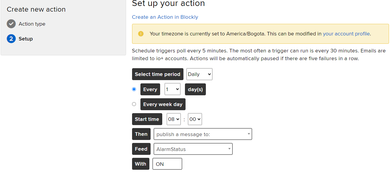
There are two options for activating the alarm clock:
- Setting up a scheduled event in Adafruit IO
- Go to the Actions tab (a picture is attached)
- Create a new Action of type Scheduled
- Choose the timing when you want to activate the alarm clock (a picture is attached)
- Pass the responsibility on to a friend
- If you would like to give a friend control over the activation of the alarm clock, you can share with him your login details to Adafruit IO and through the WakeUpYourPartner dashboard he will be able to activate the smart alarm clock
! Note that each of the ways is optional and you can combine the two (to create a scheduled alert while sharing control of the clock so that a friend can wake you up in case of an unplanned emergency, for example)