Smart HVAC Control System Using Modbus, RS-485 & Web Dashboard
by Chanchaldada in Circuits > Electronics
41 Views, 1 Favorites, 0 Comments
Smart HVAC Control System Using Modbus, RS-485 & Web Dashboard
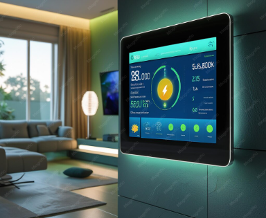
Here’s a look at a project our engineers recently wrapped up: a smart HVAC control system for a commercial office space. The client wanted to replace a legacy, manually-controlled system with something they could monitor remotely and automate based on occupancy and time of day.
We didn't just build a prototype. We designed the PCB, wrote the firmware, and shipped a fully functional unit. Here’s how we did it, including the parts list and the build steps. If you’re planning a similar retrofit, this breakdown will save you some real headaches.
The Problem with Off-the-Shelf Controllers
The client had a standard rooftop unit (RTU) with a proprietary thermostat interface. They wanted integration with their existing building management system (BMS), which spoke Modbus over RS-485. Most commercial thermostats are locked down. You can’t easily tap into their internal registers without violating warranties or dealing with obscure protocol documentation.
We decided to build a custom controller that would sit between the RTU and the network. It needed to read temperature sensors, control the compressor and fan relays, and expose all that data over Modbus. Then, we added a local web dashboard for quick diagnostics without needing a laptop with serial software.
Supplies
Before touching a soldering iron, we spec’d everything out. Here’s the exact BOM we used:
- MCU: STM32F103C8T6 (Blue Pill) – Cheap, powerful enough for the logic, and has multiple USARTs for Modbus and debug.
- RS-485 Transceiver: MAX485 – Standard, reliable, and handles the differential signaling.
- Isolated DC-DC Converter: B0505S-1WR2 – This is critical. It isolates the RS-485 side from the MCU logic to prevent ground loops in the field wiring.
- Temperature Sensors: 2x DS18B20 (waterproof probe version) – One for return air, one for supply air.
- Relay Module: 2x SRD-05VDC-SL-C relays – For switching the compressor (24VAC) and fan (24VAC) control lines.
- Power Supply: Mean Well IRM-03-5 – 3W, 5V output, for the MCU and relays.
- Web Dashboard: ESP32 (ESP32-WROOM-32) – Handles the Wi-Fi connection and serves a simple HTTP page.
- PCB: Custom 2-layer board, designed in KiCad, fabbed by JLCPCB.
- Misc: Screw terminals, 120-ohm termination resistor, TVS diodes for the bus, and a 3D-printed enclosure (we used PLA for the prototype, ABS for the final).
PCB Design and Assembly
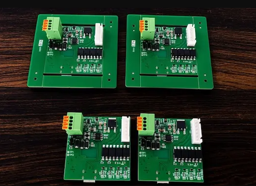
We laid out the board in KiCad. The key layout rule here is to keep the high-voltage relay traces away from the RS-485 lines. We had a single 2-layer board; we put the power section on one side and the comms on the other.
- Solder the STM32 first. Use a fine tip and flux.
- Add the MAX485 and the B0505S converter. Double-check the pinout on the converter—it’s easy to reverse.
- The DS18B20 sensors connect via 3-wire headers (VCC, GND, Data). We added a 4.7k pull-up resistor on the data line.
Firmware for the STM32 (Modbus Slave)
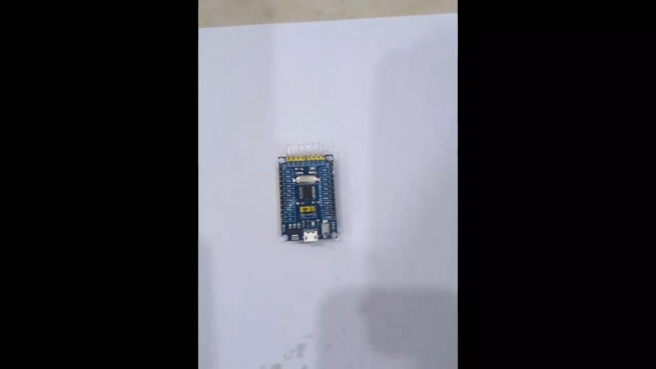
We used STM32CubeIDE with the HAL library. The core logic is a Modbus RTU slave on USART2. We mapped the sensor readings and relay states to holding registers.
- Register 0x0001: Supply temp (scaled by 10)
- Register 0x0002: Return temp (scaled by 10)
- Register 0x0003: Relay status (bit 0 = fan, bit 1 = compressor)
The tricky part was the RS-485 direction control. You have to toggle the DE/RE pins on the MAX485 after the last byte of the response is sent. We used the USART’s TX complete interrupt to do this. If you don’t, you get bus collisions.
ESP32 Web Dashboard
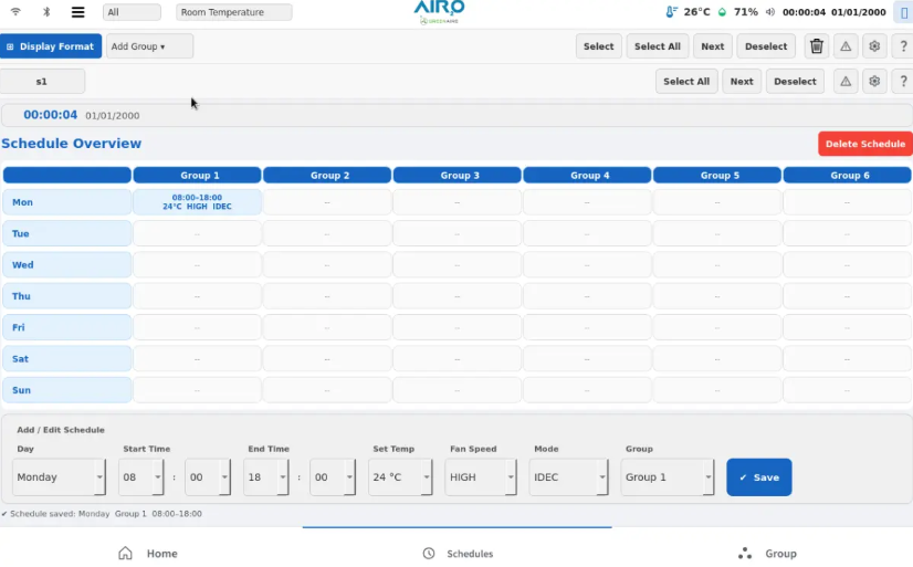
The ESP32 acts as a Modbus master. It polls the STM32 every 500ms over a simple UART connection (we used USART1 on the STM32, connected to the ESP32’s UART2). The ESP32 runs a small web server.
We used the Arduino core for the ESP32 for speed of development, but the STM32 side is pure C. The web page is simple HTML with a bit of JavaScript that fetches a JSON endpoint (`/data`) and updates the temperature readings and relay toggles.
Integration and Wiring
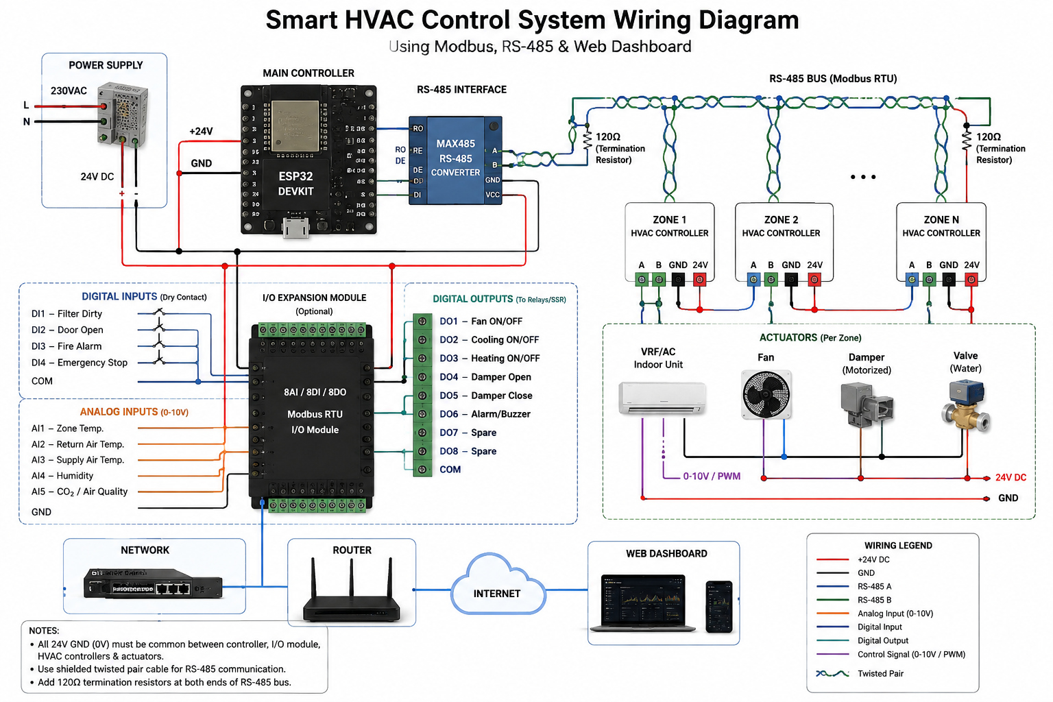
Here’s where most people mess up. The RS-485 bus needs proper termination.
- We placed a 120-ohm resistor across the A and B lines at the far end of the bus (the BMS side).
- We used shielded twisted pair cable (Belden 9841) for the RS-485 run.
- The relays are wired in series with the 24VAC control signals from the RTU. Critical: We used a separate 24VAC transformer for the relay coil power, not the one powering the RTU’s control board, to avoid backfeeding.
Enclosure and Shipping
We designed a simple DIN-rail mountable enclosure in Fusion 360 and printed it on our Prusa. It has cutouts for the DB9 connector (for the RS-485) and a small hole for the Wi-Fi antenna. The whole unit draws about 1.2W at 5V, so heat isn't an issue.
We shipped this prototype to the client for a pilot install. They connected it to their existing BMS via a Modbus TCP-to-RS485 gateway. It worked on the first poll.
Key Takeaways for Your Build
If you’re building a smart HVAC control system, don’t skip the isolation. We initially tested without the B0505S and saw random bit errors when the compressor kicked on. The isolation fixed it completely.
Also, test your Modbus register mapping with a tool like Modbus Poll before wiring it to the BMS. The BMS integrators will thank you, and it’s much easier to debug a laptop than a building controller.
The final system now runs autonomously. The ESP32 dashboard lets the facility manager override the schedule from their phone, and the BMS reads the same data for historical logging.
We’re happy to share the KiCad files or the firmware structure if you’re working on something similar. Drop us a line—we like talking shop.