Smart Home: Relay Expansion Module
by MAKAO in Circuits > Electronics
44 Views, 0 Favorites, 0 Comments
Smart Home: Relay Expansion Module
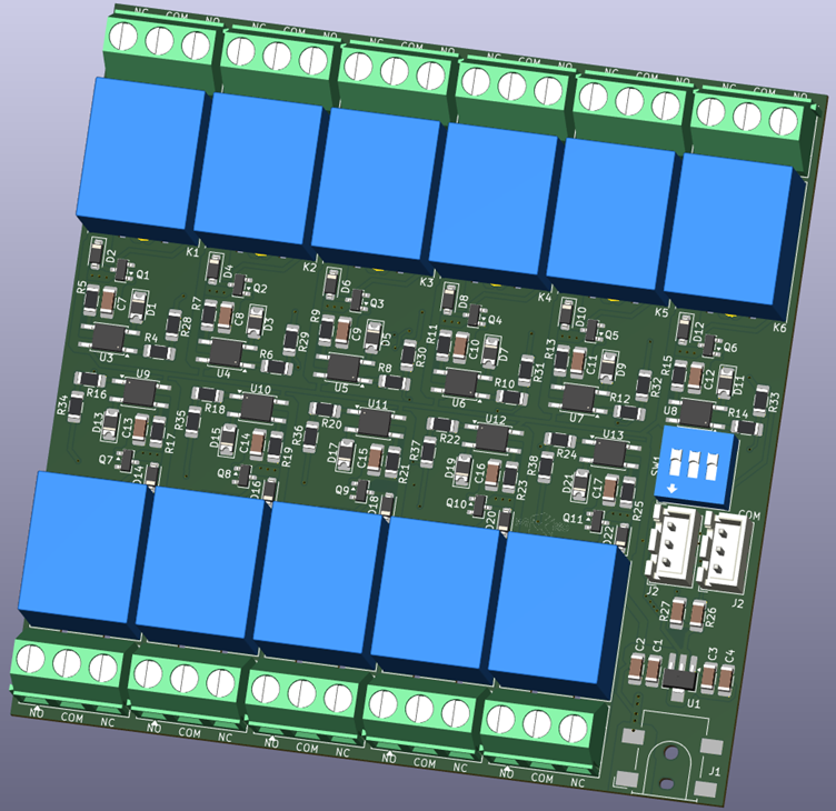
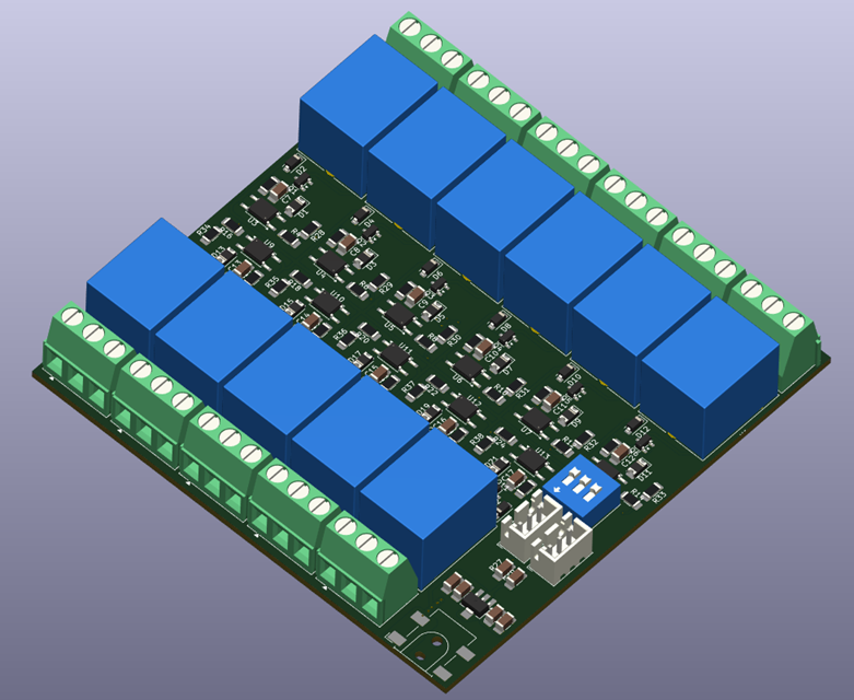
The STM32G4 smart home controller I built handles real-time I/O and brings out two independent I2C buses along its edge, specifically to leave the system room to grow. This board is the first thing plugged into that spare capacity: an 11-channel relay output module, addressed over I2C, designed to share a bus with up to seven identical siblings.
Where the main controller holds the intelligence of the system — CAN connectivity, binary inputs, its own pair of relay outputs, and the link up to the Raspberry Pi — this board does one job and does it eleven times over: accept a command over I2C, switch a relay, and light an LED to confirm it. Every channel goes through the same opto-isolation pattern established on the main controller, and because the module is address-selectable, a single I2C bus can carry a chain of these boards driving well over a hundred relay outputs before the second bus is even touched.
In this Instructable, I'll cover how this module fits into the wider system, the I2C addressing scheme and expander chip that make eight boards per bus possible, and the per-channel isolation and driver stage carried over from the main controller board.
Where This Board Fits in the System
The main controller board was designed with two independent I2C buses brought out specifically to avoid address conflicts between similar peripherals sharing a single bus — at the time, that was framed mainly around sensor expansion. This relay module is the first real use of that spare capacity, and it settles the expansion topology for simple I/O: relay and binary-I/O expansion runs over I2C, not CAN.
Each I2C bus supports up to 8 modules (addressing covered in Step 4), and with two independent buses on the controller, the system tops out at 16 relay modules × 11 channels = 176 relay outputs before the address space runs dry — a figure unlikely to be reached in a single-family installation, which is exactly the kind of margin worth designing in from day one rather than retrofitting later.
Board Overview
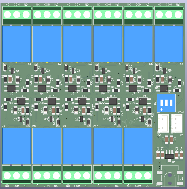
Eleven relay channels are laid out in two rows — six along the top edge, five along the bottom — each with its own 3-pole screw terminal (NO/COM/NC) sitting directly beside its relay. The strip between the two rows carries the shared control electronics: the I2C expander, the per-channel driver components, and the address-selection switch. Power enters through a DC connector in the bottom-right corner, next to the local 3.3V regulator.
The layout keeps every switched contact path short and immediately adjacent to its own field-wiring terminal, while all the control-side electronics — expander, address switch, bus connectors — stay clustered in the centre strip, physically as far as practical from the mains-voltage terminals along the board edges.
The I/O Expander — MCP23017
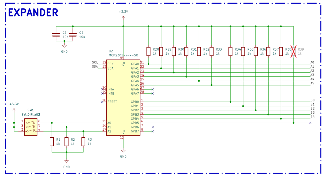
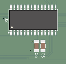
Driving 11 relay states over I2C is handled by an MCP23017, a 16-bit I2C port expander — the standard, well-proven choice for exactly this job, and one of the most widely used expanders in both the hobbyist and industrial worlds for good reason: it is cheap, thoroughly documented, and its two 8-bit ports (GPA/GPB) map cleanly onto plain register writes, with no vendor-specific driver quirks to work around.
Only 11 of the chip's 16 I/O lines are used for relay outputs here, which leaves 5 spare — real, usable margin for a future revision. An obvious use for those lines would be reading status back: auxiliary contact feedback for relay fault detection, or a bank of local manual-override switches configured as inputs, neither of which would require a second expander or a change to the bus protocol, since the register map already has room for them.
Why an I2C port expander rather than one dedicated microcontroller pin per relay: the entire purpose of this module is to multiply output count cheaply per board. An MCU able to drive 11+ outputs directly, run its own firmware, and talk I2C or CAN back to the main controller would cost more in both silicon and firmware effort than this board warrants — it has no local logic to speak of, and needs none. The MCP23017 turns "write two I2C registers" into "eleven physical relay states", which is precisely the right amount of complexity for a board whose whole job is to be a simple, reliable, addressable relay bank.
Address Selection — SW1
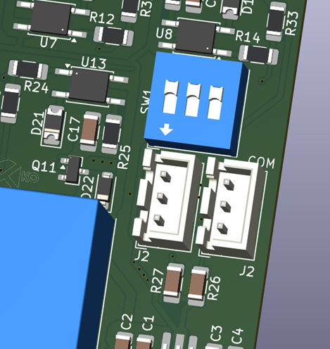
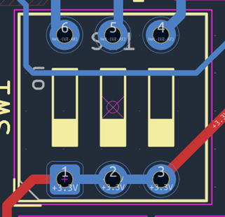
A 3-way DIP switch (SW1) sets the module's I2C address, giving 8 possible combinations (0–7) — wired to the MCP23017's own A0–A2 address pins, which is the standard mechanism the chip provides for exactly this purpose. In practice this maps onto the familiar MCP23017 address range of 0x20–0x27, with each board's switch setting claiming one slot in that range.
This is the detail that allows up to 8 boards to share one bus with no coordination on the firmware side: every board's address is a fixed, physical, human-set property, so from the main controller's point of view, adding another relay module to a chain means flipping three switches to an unused combination and connecting the bus — no re-flashing, no configuration file, no address auto-negotiation to get wrong.
One practical note for anyone building several of these boards: because address selection is purely mechanical, it is easy to end up with two boards set to the same address when assembling a batch. It is worth marking each board's assigned address on the enclosure, or with a permanent marker next to SW1, during installation — an I2C address conflict between two relay boards produces almost no useful diagnostic. Both boards simply answer the same commands, and if their outputs ever disagree, the bus starts behaving erratically with nothing obvious to point at.
I2C Daisy-Chain Connectors — J2 × 2
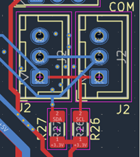
Two identical J2 connectors loop the I2C bus (VCC, GND, SDA, SCL) into and out of the board — one from whatever sits upstream (the main controller, or the previous board in the chain), and one continuing on to the next relay module. Mechanically this is a daisy chain, but electrically it is a multi-drop bus: every board sees the same four signals in parallel, and only its own address decides which commands it acts on.
Why two connectors instead of one connector plus a Y-cable or a separate junction block: a dedicated in/out pair makes the wiring topology unambiguous during installation — there is no doubt about which cable is upstream and which is downstream, and no need for a separate T-junction accessory just to insert a board into the middle of a chain.
Power Architecture
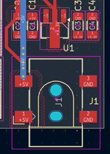
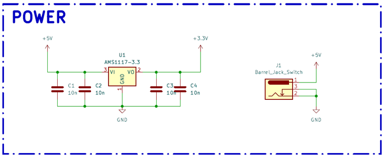
Power arrives through a DC connector at 5V — the same rail that feeds the relay coils directly, and also the input to a local AMS1117-3.3 linear regulator supplying the MCP23017 and the rest of the control electronics at 3.3V. This is the same regulator and the same topology used on the main controller board, and the same caveats carry over unchanged: it is simple and adequate at these current levels, but counterfeit AMS1117 parts are common enough that sourcing from a traceable distributor is worth the small premium — particularly across a batch of identical boards, where one marginal regulator means an intermittent fault that is painful to trace back to its source.
Worth flagging specifically for this board: unlike the main controller, where the 3.3V rail only feeds the MCU and a couple of low-current peripherals, here it is the 5V rail — not the regulated 3.3V one — that does the real work, driving up to 11 relay coils at roughly 70 mA each, based on the SRD-5VDC-SL-C's typical coil power figure (0.36 W ÷ 5V ≈ 72 mA). With every channel energized at once, that is close to 800 mA drawn from the 5V input before the regulator's own load is counted. That is comfortably within what a typical 5V supply for a board like this will deliver, but it is a number worth having to hand when sizing the power supply for an installation running several of these modules from a shared 5V source: the AMS1117 only ever sees the much smaller control-side load, while the upstream supply has to cover worst-case simultaneous coil current across every connected module.
Per-Channel Isolation and Drive
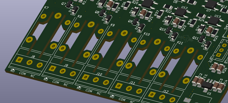
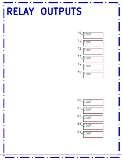
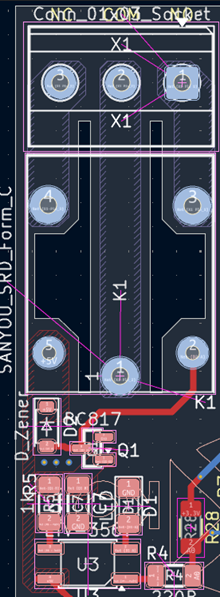
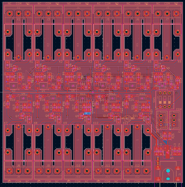
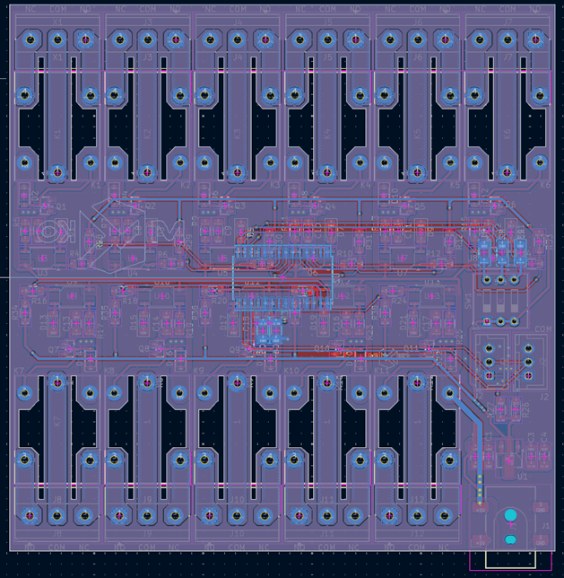
Each of the 11 channels repeats the driver chain already used on the main controller's own relay outputs: MCP23017 GPIO → LTV-356T optocoupler → BC817 transistor → relay coil, with a flyback diode across the coil to clamp the inductive spike when the relay de-energizes, and a status LED per channel for a quick visual check of which outputs are currently active.
Reading the diode numbering on the schematic, the pattern is consistent across all 11 channels: even-numbered diodes are the coil flyback protection, odd-numbered ones are the per-channel status LEDs. It is a small labelling detail, but one worth calling out for anyone tracing the schematic, since a flyback diode and an indicator LED play very different roles despite sharing a reference designator prefix.
Why keep the full isolation stage here, now that the controlling side is only an I2C expander rather than the MCU itself: the reasoning is unchanged from the main controller. These contacts switch mains-voltage loads — lighting circuits and socket outlets — and the control side deserves a proper galvanic isolation barrier regardless of what sits on the other end of it. Keeping the identical opto/transistor/flyback pattern across both boards also means one driver design to validate, source and troubleshoot across the whole system, rather than a subtly different circuit on every board type.
The Relay — SRD-5VDC-SL-C
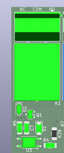
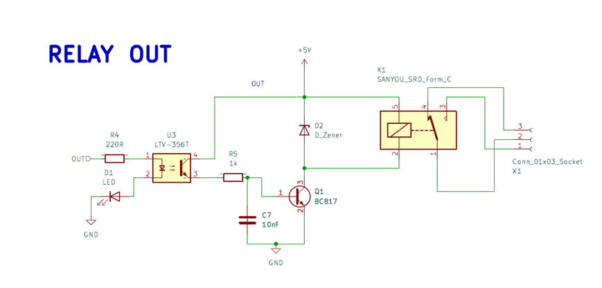
Each channel switches through a Songle SRD-5VDC-SL-C, an extremely common 5V hobbyist-grade relay that is cheap and available everywhere. Published contact ratings for this part are typically 10A at 250VAC and, depending on which manufacturer's datasheet revision you read, either 10A/28VDC or 10A/30VDC for DC loads.
Worth stating honestly: the SRD series is manufactured and rebadged by several factories, and contact ratings do differ slightly between datasheet revisions from different sources — some list 10A/250VAC alongside 10A/125VAC, others quote 10A/28VDC where another batch's paperwork says 30VDC. The practical difference is negligible for this application, but it is worth pulling the datasheet from the specific supplier a given batch of relays came from, rather than assuming every SRD-5VDC-SL-C on the market is backed by an identical document. Since the DC rating will not actually be exercised here — every channel is intended for AC mains loads only, matching the lighting, socket and roller-shutter use cases — the exact DC figure is academic for this build, but worth having on file for anyone later repurposing a channel for a low-voltage DC load.
On the coil side: the 5V coil rating matches the board's DC input directly, which is why no separate coil supply is needed — a neat piece of design economy that avoids a second voltage rail purely for coil drive, at the cost (as covered in Step 6) of the input rail having to comfortably supply the combined coil current of every active channel.
Screw Terminals — NO / COM / NC
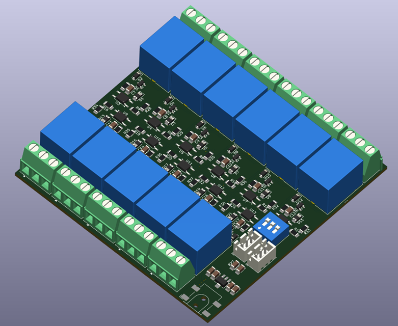
Each channel's 3-pole terminal block brings out the complete SPDT changeover contact — NO (normally open), COM (common) and NC (normally closed) — rather than just a single normally-open pair. That is a small but meaningful choice: a channel can be wired either as a conventional energize-to-switch-on output (NO + COM, the usual case for lighting or socket circuits) or inverted, using NC + COM, wherever the desired behaviour is "on unless commanded off". The latter is useful for fail-safe circuits, where losing power to the module should leave a given load in its safe state rather than simply dropping it.
Where This Leaves the System
With this module in place, the system now has a working answer to "how do I add more switched outputs": wire up another relay board, set its address switch to an unused value, and hang it off whichever I2C bus still has room. Eight boards per bus, two buses, plus the main controller's own two onboard relay channels give a realistic path from a handful of outputs up to well over a hundred, with no change to the main controller board itself.
Final Thoughts
This board does nothing clever on its own, and that is exactly the point — it is a simple, reliable, cheaply repeatable way to turn one I2C address into eleven opto-isolated relay outputs, using the isolation and driver pattern already proven on the main controller. The interesting decisions here are not in any single component but in the system-level choices: settling on I2C rather than CAN as the expansion bus for this class of board, sizing the 5V input rail around worst-case simultaneous coil current instead of just the control-side load, and keeping the same opto-isolated driver chain consistent across every board in the system rather than reinventing it per module.
Next up is starting work on the sensor expansion board — which, unlike this one, will finally put that reserved CAN bus to use.