Smart Indoor Herb Garden


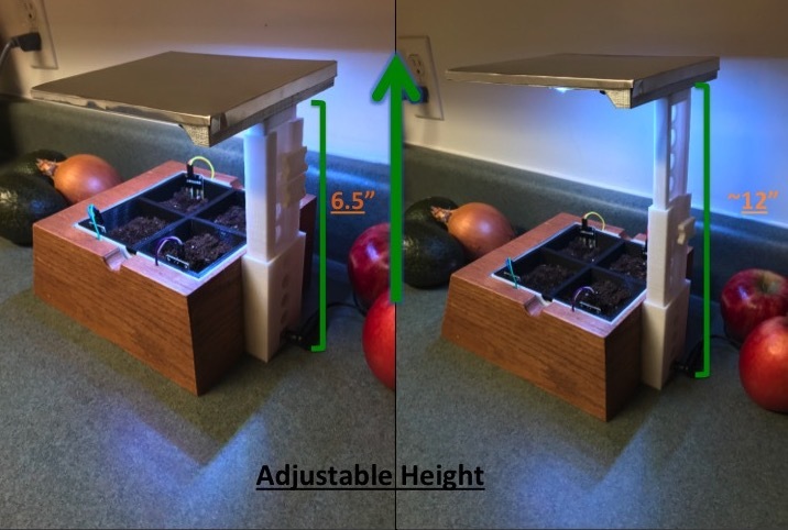


In this Instructable, I will show you how I made my smart indoor herb garden! I had a couple of inspirations for this project with the first being that I had some interest in the in home Aerogarden models. Additionally, I had a unused Arduino Mega with a TFT touchscreen shield that had just been sitting in my electronics bin for years. I figured why not try to make my own Aerogarden like herb garden using an Arduino with some of this extra time that I have during quarantine! I ended up going a little extra with the project in that I added moisture sensors to each soil aliquot but it has proven to be useful so far. All in all, I couldn't be happier with how everything turned out!
I just finished this project and planted some basil and chive seeds on 5/7/2020. This Instructable is posted on 5/11/2020. I'm hoping that plants will begin to sprout this upcoming week and I will be sure to update this Instructable with progress growth pics!
Here is a quick rundown of some of the features of my smart indoor herb garden:
- Touch screen display that displays time, day of the week, and date.
- Four 2.35" x 2.35" x 2.33" aliquots for planting herbs. Aliquot tray is inserted into a basin that collects any water drainage and isolates itself from the electronics.
- LED setting that allows user to set desired "turn on" time and duration. Additionally, user can disable LED's from turning on if they so choose.
- Moisture sensor page that indicates which of the 4 herb aliquots need to be watered.
- Adjustable grow light that gives the user ~6-8 more inches of height once the plants begin to grow.
If you are interested in seeing how I made this project or you want to make one for yourself, please follow along!
Supplies
Electronics:
- 3x N-Channel P30N06LE MOSFET
- CR1220 3V Cell Battery
- 3x 220 Ohm Resistors
- Perfboard
- DC Barrel Jack
- Wiring
Herb Garden Planter:
- White and Black 3D Printer PLA Filament (if you choose to print your own base)
- Thin aluminum sheet metal (optional)
- Shiny Metallic Spray Paint and Primer
- Wood Finish/Stain
- One Coat Polyurethane finish
Soil/Herb Products:
- Herb seeds of your choice
- Miracle Grow Topsoil
Miscellaneous:
- Electrical Tape/Painters Tape
- Hot glue gun
- 3D printer (optional)
- Exacto Knife
- Sandpaper (~220 + Grit)
- Soldering iron + Solder
- Cyanoacrylate Superglue
- Tools (Wire cutters, scissors, needle nose pliers)
Setting Up the Electronics


There are essentially 4 main components to the electronics portion of the project with the brain of the components being an Arduino Mega 2560. 1) The TFT Touch Screen shield. 2) The RTC Clock Module. 3) The Soil Sensors. 4) The MOSFET transistors and the LED Strip. I utilized a Mega for this project as it provided me with additional pins after placing the touch screen shield onto the Mega. There are many tutorials for each of the 4 major components I listed above for this project and I will link some of the ones I used as well as provide some add additional information that I came across along the way.
Please refer to my Fritzing breadboard and schematic for the basic layout of the circuit. NOTE: Fritzing did not have the exact soil sensor that I used in my project. The ones I used also came with a LM393 comparator circuit and I tried as best as I could to replicate the wiring in the Fritzing images. See below for more information on the exact wiring if it is still confusing.
1) Arduino Mega and the 2.8" TFT Touchscreen
Useful Links:
Adafruit Tutorial: Basics on connecting the shield, installing the appropriate libraries, and running example codes.
I believe I purchased my touchscreen shield from Adafruit and definitely used their tutorial for help on initial setup and running the example codes. Other than connecting the shield appropriately, there really is not much more to it until the coding portion in the next step. The one important step however is clipping the Vin pin on the shield that connects into the Arduino Vin pin. Clipping this pin allows you to have pin access in order to provide the arduino power from an external power supply, so be sure to do that.
2) The RTC Clock Module
Useful Links:
Adafruit Tutorial: Different breakout board than I used in my project but same DS3231 chip.
Connecting the real time clock module to the Mega is also straightforward. All you need is 5V, GND, SDA, and SCL connections. For my project, I connected SDA and SCL from the clock to pins 20 and 21 respectively on the Mega. I also used Adafruit's tutorial on initializing the clock but more on that in the next step. For now just complete the wiring as depicted.
3) The Soil Sensors
Useful Links:
Instructables Tutorial: User mdabusaayed has a great and simple tutorial on how to utilize these sensors!
I actually ordered these sensors after starting the electronics portion of the project. In place of these sensors during initial testing, I used regular switches as digital inputs which is why those are present in my early breadboard circuit. As user mdabusaayed notes, these soil sensors can be used as digital inputs OR analog inputs. Because I just wanted these sensors to tell me if the soil was dry or not I only utilized their digital output pins. Each needs a 5v and GND pin connection and I used pins 23-26 on the Mega to connect their digital outputs
4) The transistors and RGB LED strip
Useful Links:
Arduino-LED Light Strip Tutorial: These links are of the same Make Project which show how to utilize MOSFETS and arduino digital output pins to drive and RGB LED Strip
Arduino-LED Light Strip Video:
I picked up a cheap RGB LED Strip from FiveBelow that can be powered from 5V. The Arduino digital output pins cannot supply enough current for the strip which is where the MOSFETS come into play. The linked tutorial explains the circuit in much better detail than I can so check that out if you're interested on why I did this. Follow the wiring in my circuit diagram in order to connect the strip and MOSFETS to the arduino. Disclaimer: Now I realize there is a ton of research on specific plant growing LEDs with X amount of wattage at Y frequencies. I highly doubt that my cheap $5 strip meets much of those criteria but I figured some light is better than none and I'm crossing my fingers that I'll get some herb growth here in the next few weeks :p As mentioned in the intro, I will continue to update this Instructable should I need to use a more robust LED light/strip.
Arduino Program


When creating my program, I had a few goals in mind with what I wanted it to accomplish. First, I wanted to have the touch screen display the current time and date. Second, I wanted a few functional images on the screen that the user could identify and press to take them to different screens with additional options (watering bucket to moisture sensor page and the settings to the LED settings page.) Finally, I wanted an image on the screen to tell the user if the LED lights were on or not (indicated by the lightbulb).
The code is somewhat long so I will not go line by line but rather highlight general features of what the code does. It may not be perfect but it accomplishes what I want it to accomplish. Feel free to download and tweak my code as you desire! There were some great Youtube videos that helped me when it came to writing the code: How to Mechatronics and educ8s.tv had a couple great tutorials. I do want to mention that the images of the watering bucket, light bulb, and setting logo were printed on the screen from their bitmap values. Image2cpp is a great tool that I used that automatically converts images into bitmaps.
If you are not interested in my thought process for the code, ignore what is below and download my .ino program as well as the .c file. Be sure to place both in the same folder. Connect your Mega to the computer via the USB port and using the Arduino IDE, upload the program to your Mega!
Indoor_Flower_Pot.ino code highlights
Initial
- Include Adafruit libraries (GFX, TFTLCD, TouchScreen.h, RTClib.h)
- Define touchscreen pins/variables (much of this I copied and pasted from Adafruit's example code on the TFT touchscreen
- Define variables used throughout the program
Void Setup
- Connect to TFT touchscreen
- Configure the soil sensor pins and the led pins using the pinMode() function
- Draw the home screen (I made specific functions for my program in order to draw each screen. You can find those at the bottom of my program after void loop())
Void Loop
- Draw the home screen if that's what is selected
- Check the time and update the screen if time has changed
- Check the time and see if it falls between the LED "On Time" and the LED "Timer"
- If so, turn on the LED's and draw the lightbulb on the screen
- If not, turn of the LEDs and remove the lightbulb from the screen
- Draw the moisture sensor page if the water bucket is selected
- Read the soil sensor inputs and fill in the corresponding circle if the soil is dry
- If the soil is still moist, keep the circle unfilled
- Draw the LED settings page if the settings image is selected
- Read and store the On Time, AM or PM, and the Timer.
- If LED OFF is selected, keep LED's off regardless of the On Time or Timer
Designing the Herb Garden and 3D Printing


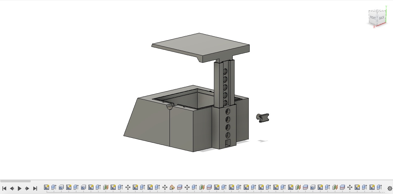
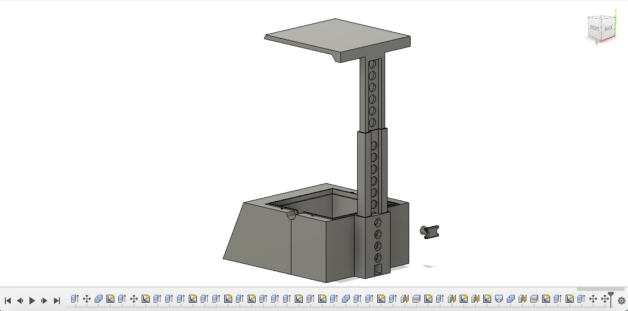

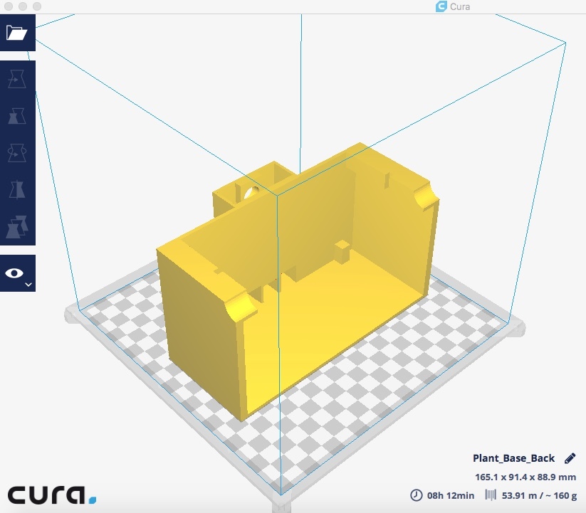
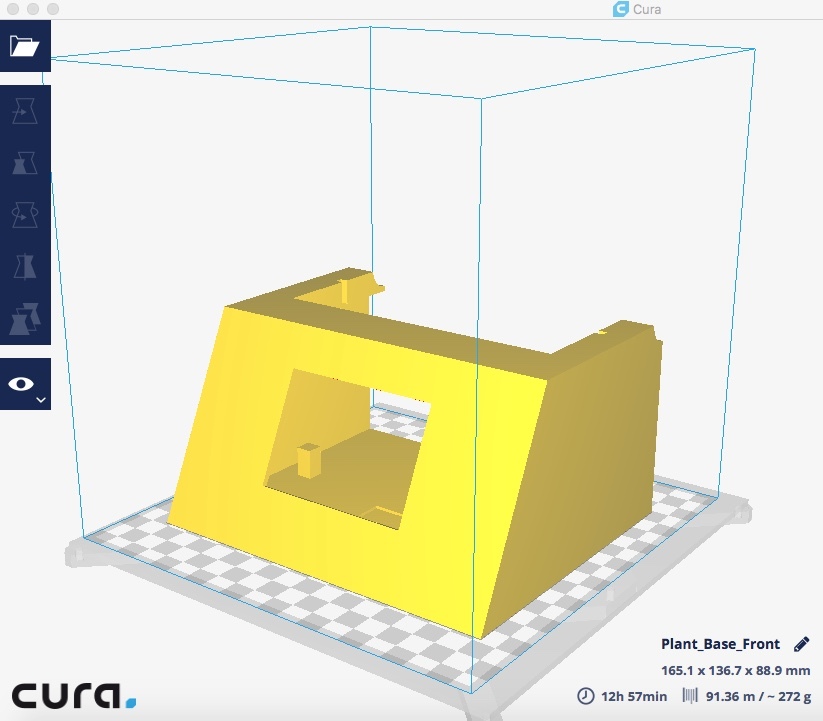


I knew before designing the Herb Garden that I wanted to wrap the base with Veneer. Because of this, I needed to create a somewhat square design with sharp corners rather than a more rounded design as the veneer would likely not adhere as well to something more elliptical. Another feature that I wanted was an adjustable shaft for the LEDs in order to accommodate growth of the plants. Additionally, I needed room to house the touchscreen/electronics as well as a separate plant basin that would contain any water and isolate that from the electronics. Finally, I created my own tray insert for the herbs that had 4 separate aliquots and fit perfectly within the basin. I'm happy with how the design turned out! I used Fusion 360 for this project and I've included my .stl files and .gcode files for everything so feel free to download, tweak, and print!
The planter base was too large to fit in my printer so I did have to print that in two parts. I printed everything in white PLA filament with the exception of the tray insert that I printed in black. I used Cura as my slicing software and my printing details are below. Let me know if you'd like to see more pictures of each part in the slicing software.
Slicing Software Details:
- My Printer: Maker Select Printer V2
- Nozzle: 0.4mm
- Filament: Black and White PLA filament 1.75mm
- Printing Temp/Build Plate Temp: 210C / 60C
- Print Speed: 60 mm/s
- Infill: 25%
- Enable Support: Yes, everywhere
- Build Plate Adhesion: 3mm Brim
Finishing the Herb Garden


Because the herb garden base printed in two parts the first step was to glue them together using a quick cyanoacrylate superglue. The pictures highlight some of the most important steps and I'll list them out below based on part.
Herb Garden Base:
After gluing together the two parts, I took medium grit sandpaper and roughened up the base a little bit. I then laid out my veneer and traced out all 4 sides of the base as well as the top onto the veneer. I did not want to veneer the shaft so I kept that bare. I used an exacto knife to cut out the veneer. Be cautious when tracing and cutting the veneer to ensure that the wood grain will be in the proper direction upon gluing. I did end up making this mistake but luckily it was on the back and it is hard to tell. I then applied a small amount glue to the veneer, enough to cover the entire surface, and adhered it to the herb garden base. I did two sides at a time so that I could add weights/clamps.
Once all veneer was glued and dried, I took 220 grit sandpaper and manually smoothed the base. You'll want to be careful and patient here so as to not accidentally catch a rough corner of your veneer and rip it off. The patience part is important as it will take some time to round out the edges and make everything look smooth. I did end up using a small amount of wood filler for some of the bigger cracks that I couldn't round while sanding.
After sanding was complete, I used a couple coats of Minwax wood finish and followed their instructions when applying. After letting sit for ~24 hours, I applied a one coat polyurethane to the base to give it a nice smooth shine!
Planter Basin:
This step is probably not needed but I was paranoid about water potentially leaking onto the electronics. Even though I doubt much water will be draining from the tray insert into the basin at all, I still went ahead a added a small amount of silicone to the basin corners.
LED Light Support
I wanted to paint the top of the light support in a metallic shine to give it garden nursery light feel. I did this by taping over the support shaft with painter tape and then applying a layer a primer to the exposed area. Once dry, I followed with two coats of the metallic shine spray paint. Oddly enough, I found a thin piece of sheet metal in my work area after painting the piece and thought that would look even more realistic and better than the spray paint. I traced the area of the top of the light support, cut the metal out, and used a vice grip to bend metal. I then glued it on the top. I used steel wool to clean off the metal and give it a nice shine.
Finalizing the Electronics and Wiring


Now that the herb garden base was finished and the LED light support was painted, the final step was completing the wiring and adding in all of the components! I'll again list out each important step below. I found that a lot of wire and hot glue was my best friend.
Perfboard:
I got a small perfboard and laid out the MOSFET's, RTC module, and resistors onto it to get an approximate size. I then cut it down and began soldering the components. You can really design your perfboard however you'd like. You'll see on my perfboard that I had one main (+5V) line as well as one main (GND) line. Realize that by the end of it your perfboard will look like a bad hair day with wires going everywhere. This is because you'll need 7 wires going to your arduino (SDA, SCL from the RTC module, Vin, GND, and the 3 digital pins connected to your resistor/base pin on the MOSFET's.) You'll also need an additional 8 wires coming from it to your moisture sensors (4 positive wires going to each soil sensor 5v pin, and 4 ground wires going to each soil sensor ground pin).
LED Light Strip on Light Support:
After unraveling the LED, I found that 2 sections of the strip could fit the length of the support before I had to cut it. Once I had all of the strips, I used hot glue to glue them in place giving a little room between each strip. I then used flexible 28 gauge wire to solder and connect each (+)-(+), B-B, R-R, and G-G to their respective pads. Once finished, I tested the strip to make sure all pads were soldered correctly before feeding wire through the support shaft.
Final Assembly:
I began final assembly by hot gluing the DC jack in place. I then fed 4 small flexible 28 gauge wires from the base, through the mid shaft, and up through to the light support. NOTE: it is important to cut the wire to a length that will reach through to the lights even when the mid shaft and light are fully raised. I then soldered each wire to their respective pads on the light. The (+) wire was connected directly into the DC jack.
From the (+) DC jack terminal, I connected a wire and soldered the other end to the 5V line on the perfboard. I repeated that process from the (-) DC jack terminal to the ground line.
I then used a dab of hot glue and glued the perfboard into place on the bottom of the herb garden base. I connected the appropriate wires to the arduino based on my schematic and fit the touchscreen through the window on the front of the base. Depending on how tight the fit is, you may or may not need to use a touch of hot glue to seal it into place.
Finally, I hot glued the four soil sensor modules into place on the side walls ensuring that each sensor was appropriately placed for the corresponding read out on the touchscreen moisture sensor page. After that, I connected the four soil sensors, fed the wires through the tiny slots, and added the plant basin with the tray!
And just like that the wiring is finished!
Soil, Seeds, and Complete!


The last step is obtaining some potting soil and seeds of your choice! I filled each aliquot of the tray insert with potting soil until about 0.5in" from the top. I created little impressions in the center of each soil, added a few seeds to each, and covered with ~0.25" of soil.
I then added the tray to the plant basin and placed that into the herb garden base! When watering, I found the best way to do this is by using a turkey baster and adding water until the soil seems moist. I can then confirm that the soil is watered enough after waiting a few minutes and checking the moisture sensor page. If the circles are unfilled that indicates that the plants are watered appropriately!
Now heres to hoping the herbs actually grow :P I hope you enjoyed this Instructable and look forward to seeing if any of you make your own. Happy making!