Smart Paper Towel Stand
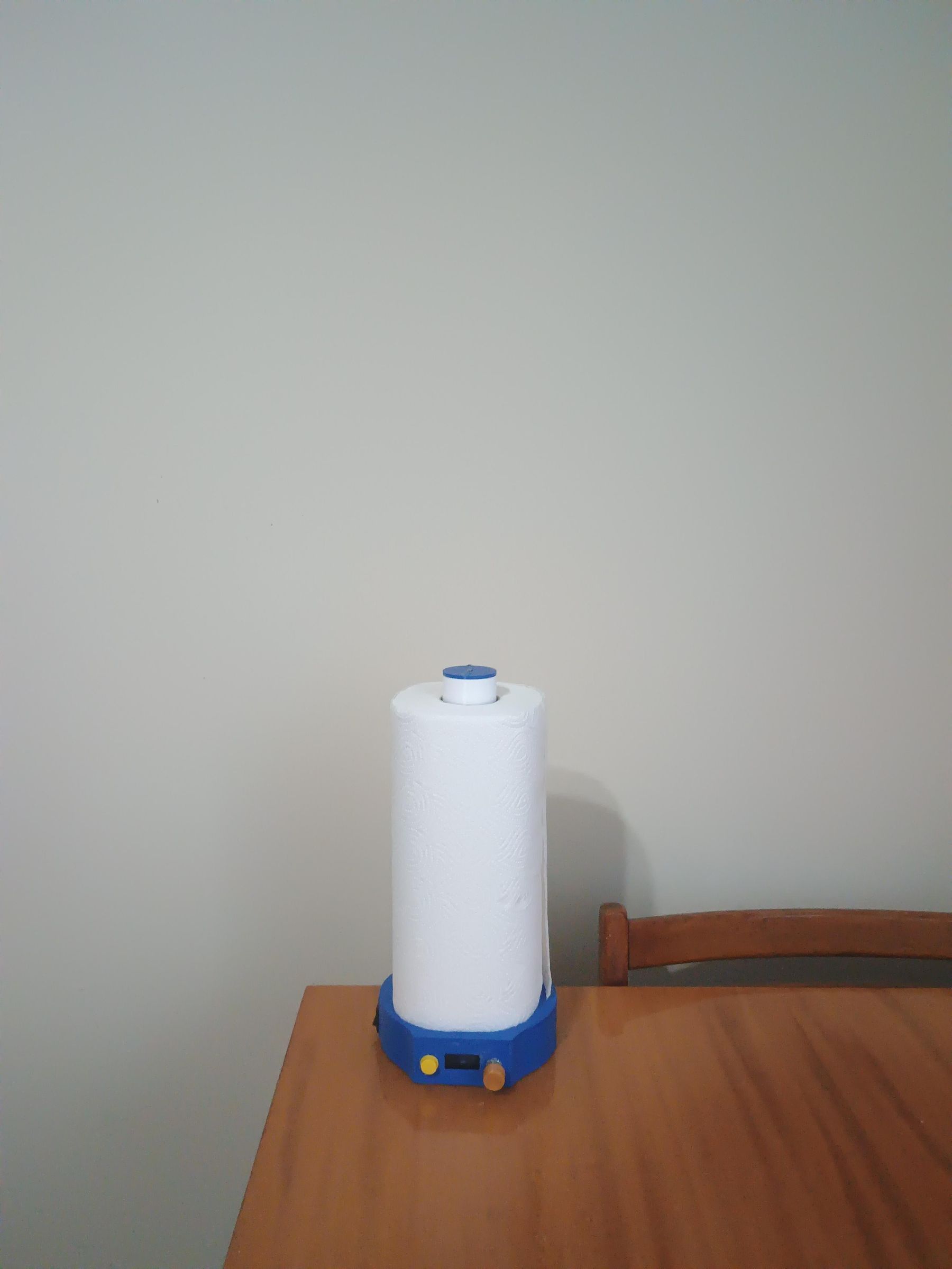
.jpeg)

.jpeg)
.jpeg)
I made this project for the colors of rainbow contest. It is a stand for paper towels with some electronic features. RGB LED with multiple modes controlled by a button, RTC module so it can show time and date, DHT11 temp&humidity sensor for simple indoor room "weather" station and also an option to set timer, for which there is a passive buzzer to announce end or stopwatch, both controlled by rotary encoder.
Supplies

.jpeg)
Arduino UNO
9V battery
DC barrel jack
rocker switch
OLED display 0,96 (I used the 4 pin version)
rotary encoder
button
RTC module
DHT11 temp&humid sensor
passive buzzer
RGB LED
wires
Arduino UNO prototyping board/perfboard
3D printing material (I used PETG though PLA is good enough)
brass threaded heat inserts:
4mm 6pieces
10mm 4pieces
bolts:
M3x5 6pieces
M3x30 4pieces
OTHER:
soldering iron
super glue
Brainstorming&Prototyping
.jpeg)
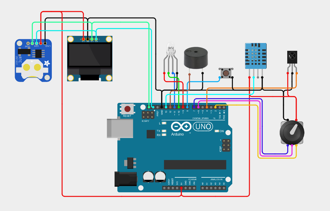
I started with brainstorming as one should and ended with pretty solid project. I used mainly components that I allready had at home and ordered arduino uno protopyping board since I didnt had time for custom PCB. I designed the circuit schematic in cirkit designer. After that I used the schematic to make breadboard prototype and "vibe-coded" simple code for arduino.
3D Model and Printing


.jpeg)
.jpeg)
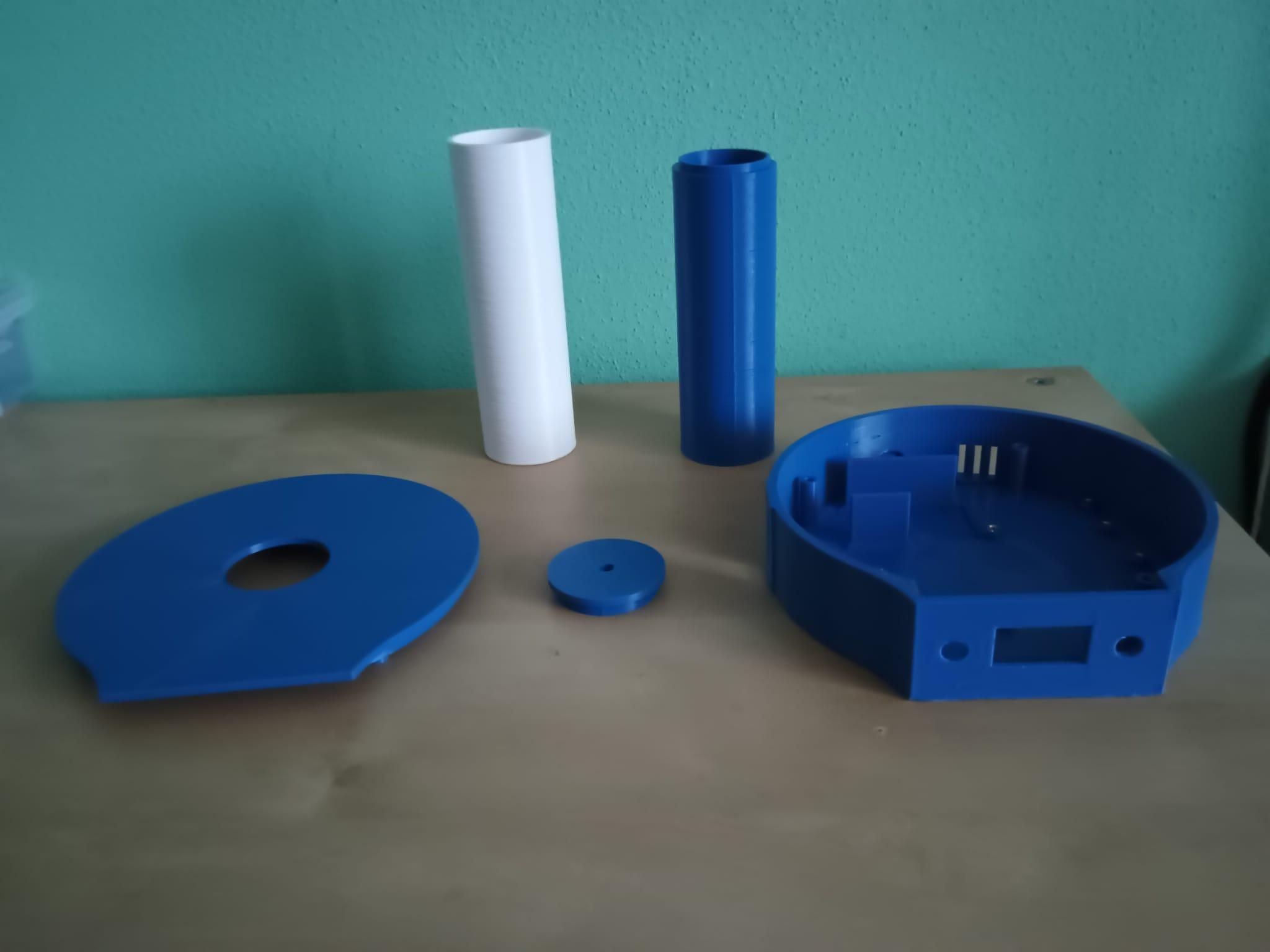
Once I had a functioning prototype I began working on modeling the enclosure. I used Autodesk Fusion for this task. The start was a little bit rough but after I got a simple shape it was easy to continue and make some modifications for the modeled enclosure. In the bottom part sits all the electronic (with the exception of RGB LED since it sits at the top of the stand inner cylinder). All components have their designed holes or mounting systems. After I was done with modeling I printed it on my Prusa mk3 in blue PETG.
Code Optimization

The next step was correcting the little mistakes from the "vibe-coding" like centering the text or making the fading smoother on the RGB LED. I also changed some pins since it would be easier to solder them and the wires wouldnt go over each other(although in the end, they unfortunately did exactly that :(
Here are the pins I used for the final version:
Arduino UNO: Component:
OLED display
A4 SDA
A5 SCL
Button
D8 pin 1
gnd pin 3
rotary encoder
D2 CLK
D4 DT
D7 SW
RTC module
D11 CLK
D13 DAT
A0 RST
passive buzzer
D12 +
gnd -
DHT11
D5 DAT
RGB LED
D9 R
D10 G
D6 B
all other pins on components are VCC or GND which should be easy to wire :)
Downloads
Assembly
.jpeg)
.jpeg)
.jpeg)
.jpeg)
.jpeg)
.jpeg)
This was probably the most satisfying step since I love soldering and putting the 3D printed enclosure together (and also to finish a project:)
I inserted the threaded inserts into their respective positions with soldering iron. Next I soldered all wires to the prototyping board, screwed in and mounted arduino and RTC module. After that, I cut the + wire on DC barrel jack so I could solder the rocker switch and the project could be turned off at any time. Then I used super glue to secure all components in their positions since most of them couldnt be screwed in. Next I inserted a 3d printed encoder knob I found on printables (you can use whichever you like or design your own). Then I glued the separate parts of inner cylinder together and mounted RGB LED on the top. The last step was screwing in the M3x30 bolts from the bottom and securing the bottom housing with the rest of the stand and the project is done :)