Smart Study System: an IoT-Based Study Monitoring and Focus Tracking
by fara7alhabib in Circuits > Arduino
20 Views, 0 Favorites, 0 Comments
Smart Study System: an IoT-Based Study Monitoring and Focus Tracking
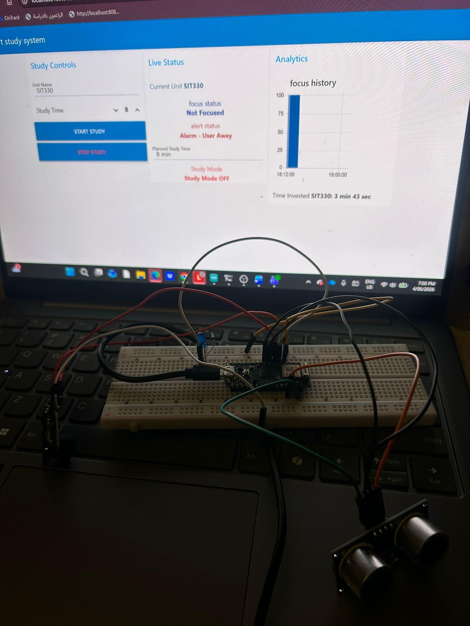
This project presents a Smart Study Environment Monitoring System developed using an Arduino Nano 33 IoT, an HC-SR04 ultrasonic sensor, an LED, a buzzer, MQTT communication, and a Node-RED dashboard.
The purpose of the system is to help students maintain focus during study sessions by automatically monitoring their presence at the study desk. The ultrasonic sensor detects whether the student is present or away. When the student leaves the study area for an extended period, the system activates visual and audio alerts through an LED and buzzer. Real-time data is transmitted using MQTT and displayed on a Node-RED dashboard, which shows focus status, study mode, alert status, study time, and a summary of time spent on different units.
This project demonstrates how IoT and embedded systems technologies can be used to improve study habits, increase productivity, and provide real-time feedback to users.
Supplies
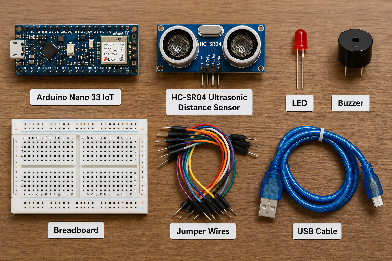
Tools and Materials
Hardware Components
- Arduino Nano 33 IoT
- HC-SR04 Ultrasonic Distance Sensor
- LED
- Buzzer
- Breadboard
- Jumper Wires
- USB Cable
Software Tools
- Arduino IDE
- Node-RED
- MQTT Broker (broker.emqx.io)
- Google Chrome Web Browser
Arduino Libraries
- WiFiNINA Library
- ArduinoMqttClient Library
Development Tools
- GitHub (source code repository)
- Instructables (project documentation)
- Windows 11 Operating System
Communication Protocol
- MQTT (Message Queuing Telemetry Transport)
Dashboard Platform
- Node-RED Dashboard for real-time monitoring and visualization
Prepare the Hardware
First, prepare the required hardware components: Arduino Nano 33 IoT, HC-SR04 ultrasonic sensor, LED, buzzer, breadboard, jumper wires, and USB cable.
The ultrasonic sensor is used to measure the distance between the student and the study desk. The LED and buzzer are used as alert outputs when the student moves away from the desk.
Connect the Ultrasonic Sensor
Connect the HC-SR04 ultrasonic sensor to the Arduino Nano 33 IoT.
The wiring used in this project was:
- VCC → 5V
- GND → GND
- TRIG → D4
- ECHO → D5
The TRIG pin sends the ultrasonic signal, and the ECHO pin receives the reflected signal. The Arduino uses this reading to calculate the distance between the sensor and the user.
Connect the LED and Buzzer
Next, connect the LED and buzzer to the Arduino.
The wiring used was:
- LED signal pin → D2
- Buzzer signal pin → D3
- LED ground → GND
- Buzzer ground → GND
The LED and buzzer are activated when the system detects that the user has moved away from the study desk for more than the configured time threshold.
Install Arduino IDE and Required Libraries
Install Arduino IDE on the computer. Then install the required libraries:
- WiFiNINA
- ArduinoMqttClient
These libraries allow the Arduino Nano 33 IoT to connect to WiFi and communicate with the MQTT broker.
Upload the Arduino Code
Open Arduino IDE and paste the Smart Study System code.
Update the WiFi details in the code:
The MQTT broker used in this project was:
After updating the WiFi details, select the correct board:
Then select the correct COM port and upload the code.
Test the Sensor Readings
After uploading the code, open the Serial Monitor in Arduino IDE.
Set the baud rate to:
The Serial Monitor should display the distance reading, motion status, alert status, and study mode.
Example output:
If the user moves away from the sensor, the output changes to:
Install and Run Node-RED
Install Node-RED on the computer.
Open Command Prompt and run:
When Node-RED starts, open the editor in a web browser:
The dashboard can be opened using:
Create MQTT Nodes in Node-RED
In Node-RED, create MQTT input nodes to receive data from the Arduino.
The MQTT topics used were:
These topics receive the focus status, alert status, study mode, and distance readings from the Arduino.
Create the Dashboard
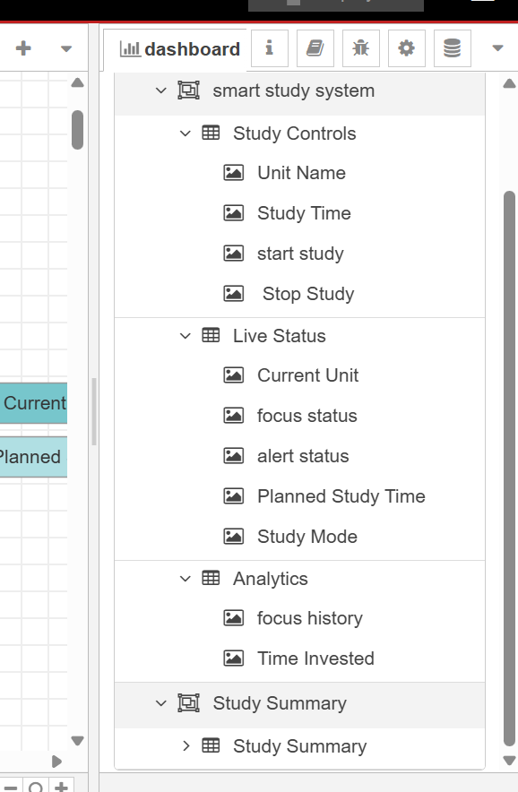
Create a Node-RED dashboard with the following sections:
Study Controls
- Unit Name input
- Study Time input
- Start Study button
- Stop Study button
Live Status
- Current Unit
- Focus Status
- Alert Status
- Study Mode
- Planned Study Time
Analytics
- Focus History graph
- Time Invested
Study Summary
- Summary of all units studied
- Time spent on each unit
The dashboard allows the user to monitor study progress in real time.
Test the System Operation
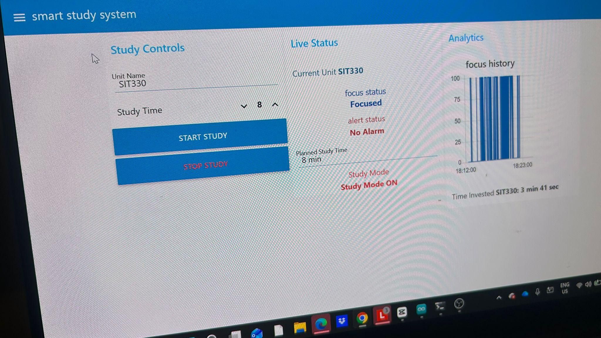
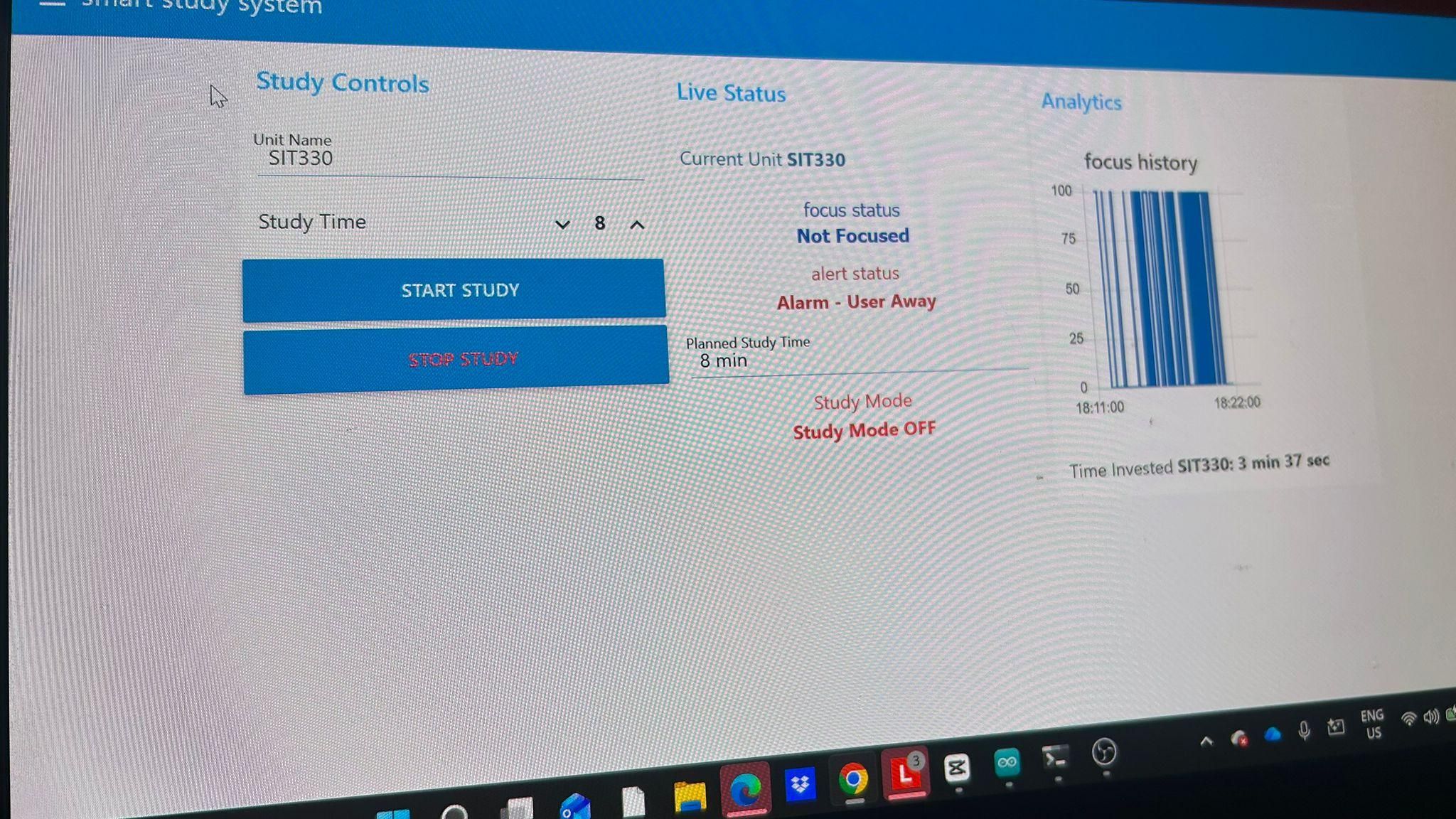
To test the system:
- Open the Node-RED dashboard.
- Enter the unit name.
- Set the planned study time.
- Sit near the ultrasonic sensor.
- Check that the dashboard shows:
- Focus Status: Focused
- Alert Status: No Alarm
- Study Mode: ON
- Move away from the desk.
- Wait for the away threshold time.
- Check that the LED and buzzer turn on.
- Check that the dashboard shows:
- Focus Status: Not Focused
- Alert Status: Alarm - User Away
- Study Mode: OFF
- Return to the desk and check that the LED and buzzer turn off.
View the Study Summary
The Study Summary page displays all units that have been studied and the amount of time spent on each unit.
Example:
This allows the student to track study time across multiple subjects.
Fault Tolerance Features
The system includes fault tolerance features to improve reliability.
If the ultrasonic sensor gives an invalid reading, the system does not immediately trigger the alarm. This helps reduce false alerts.
If WiFi or MQTT communication fails, the Arduino continues running the local monitoring logic and attempts to reconnect. Once the connection is restored, dashboard updates resume.
A delay is also used before activating the alarm, so the system does not trigger an alert if the user only moves briefly.
Access the Source Code
The complete source code for this project, including the Arduino program and Node-RED implementation, is available on GitHub.
The repository contains:
- Arduino Nano 33 IoT source code
- MQTT communication implementation
- Node-RED dashboard flow
- Project documentation
- System diagrams
Users can clone or download the repository and follow the steps in this guide to recreate the Smart Study Environment Monitoring System.
Final Result
The completed Smart Study Environment Monitoring System successfully monitors user presence using an ultrasonic sensor, tracks study sessions, records study time for different units, and provides real-time feedback through a Node-RED dashboard.
The system automatically activates an LED and buzzer alert when the user leaves the study area for an extended period and returns to normal operation when the user comes back. The dashboard provides live monitoring, focus history, study mode information, and study summaries, helping students improve productivity and maintain focus during study sessions.
This project was completed as part of SIT210/SIT730 – Embedded Systems Development, School of Information Technology, Deakin University.