Smart Temperature-Controlled Fan Using DHT11 Sensor and Arduino With PictoBlox
by santunayek387 in Circuits > Arduino
157 Views, 0 Favorites, 0 Comments
Smart Temperature-Controlled Fan Using DHT11 Sensor and Arduino With PictoBlox

This project automatically controls a fan based on the surrounding temperature using a DHT11 temperature and humidity sensor, Arduino, and PictoBlox. When the temperature rises above a predefined value, the fan turns ON automatically. When the temperature falls below the threshold, the fan turns OFF. The current temperature and humidity values are displayed in PictoBlox in real time.
Supplies
Arduino Uno
DHT11 Temperature & Humidity Sensor
DC Fan (or LED for simulation)
Relay Module (for actual fan control)
I2C 16x2 LCD Display
readboard
Jumper Wires
USB Cable
Power Supply (9V)
PictoBlox Software
Circuit Connection
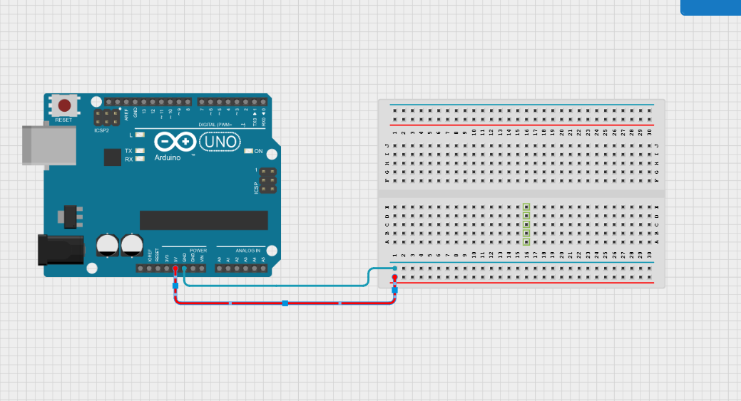
Connect the GND pin of Arduino Uno to the Breadboard '-' & 5v pin of ardunio uno to Breadboard '+'
Circuit Connection
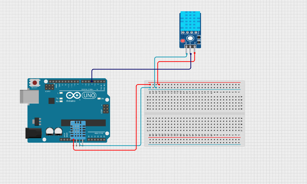
Connect the GND pin of the DHT11 sensor to the breadboard '-' & Vcc pin of the DHT11 sensor to the breadboard '+'.
Then, connect the DATA pin of the DHT11 sensor to D4 of the Arduino Uno.
Circuit Connection
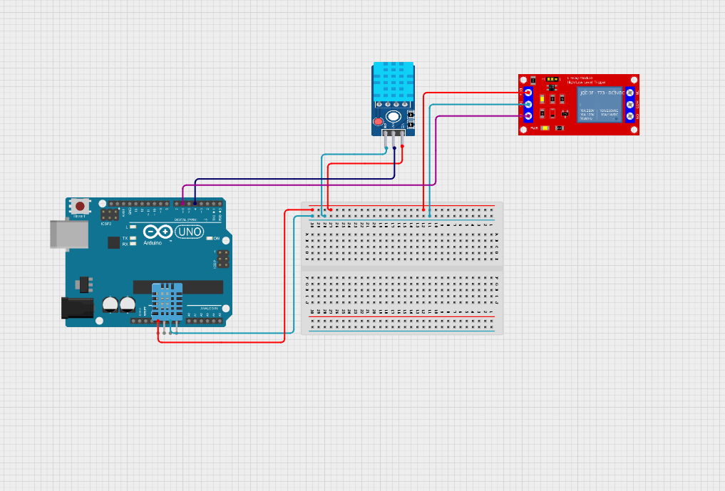
Connect the GND pin of the relay to the Breadboard '-' & Vcc pin of the relay to the Breadboard '-'.
Then, connect the 'In' Pin of the relay to D6 of the Arduino Uno
Circuit Connection
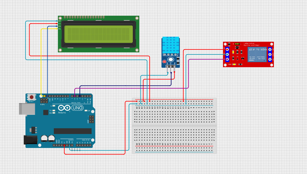
Connect the GND pin of the I2C Display to the Breadboard '-' & Vcc to Breadboard '+'.
Then connect the SCL pin of the I2C display to the Arduino SCL pin & SDA pin of the I2C Display to the Arduino SDA pin.
Circuit Connection
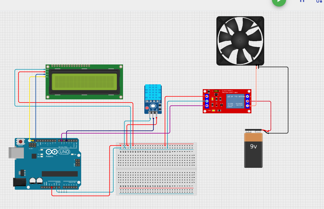
Connect the positive (+) wire of the 9V power supply to the COM terminal of the relay.
Connect the NO (Normally Open) terminal of the relay to the positive (+) terminal of the fan.
Connect the negative (-) terminal of the fan directly to the negative (-) terminal of the 9V power supply
Circuit Diagram
Code
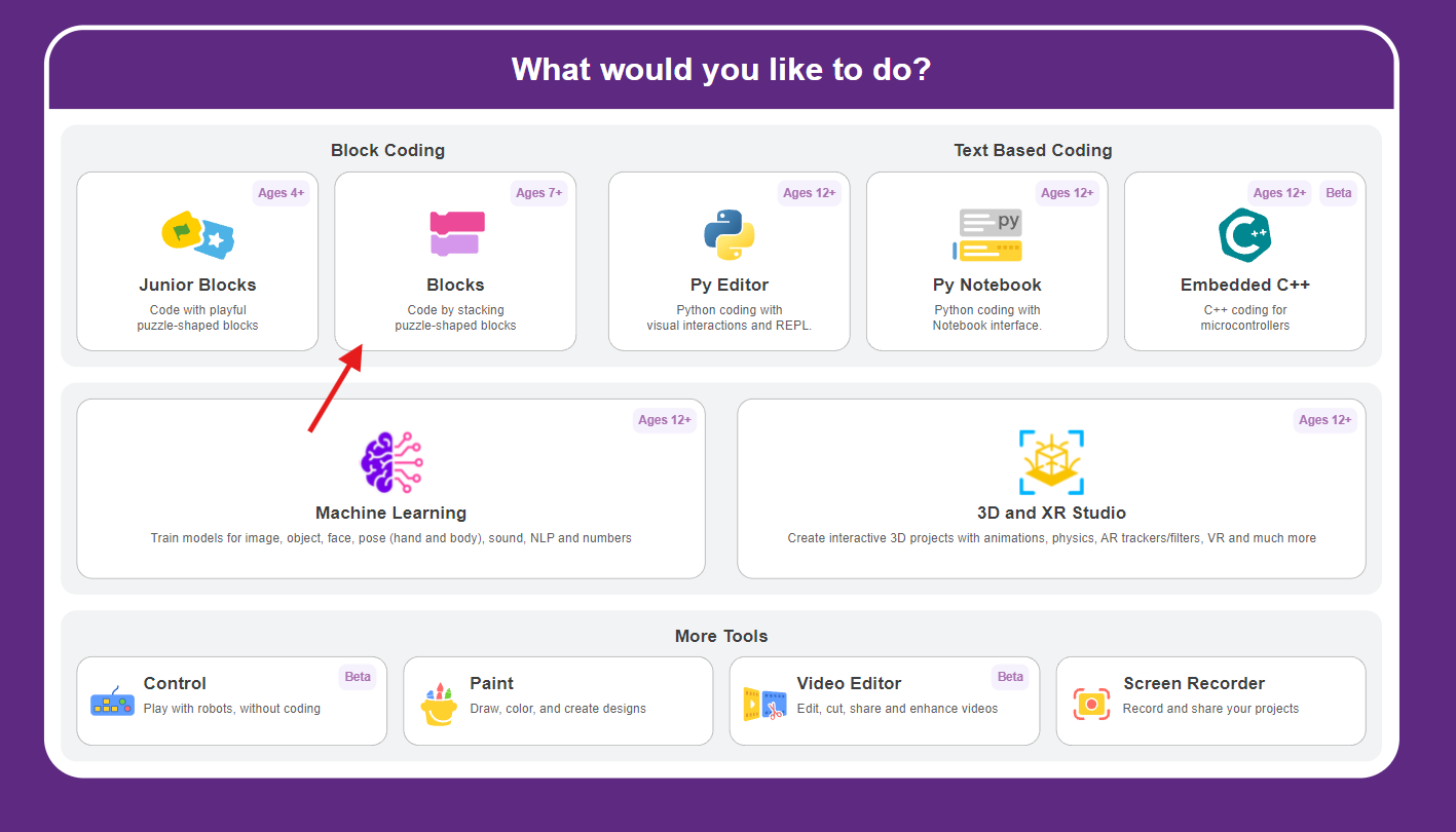
Let's complete the code by following all the steps below.
Open PictoBlox Software & select the block coding environment.
Code
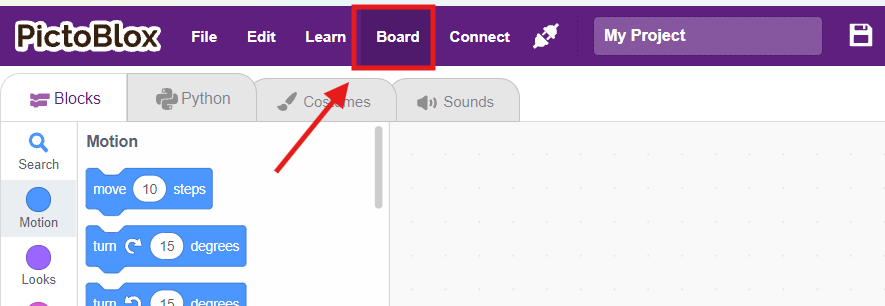
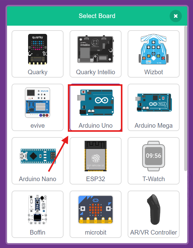
Click on the board in the menu bar & select Arduino Uno, board.
Code
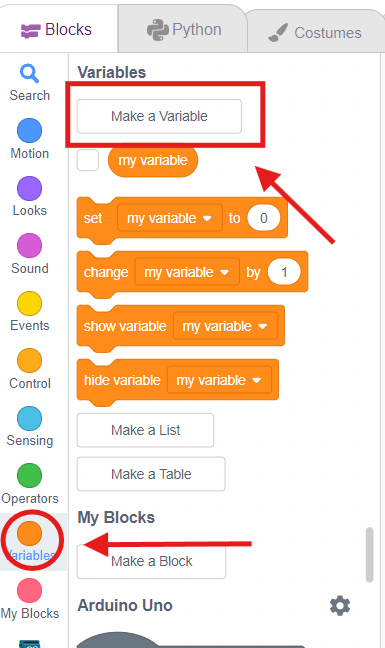
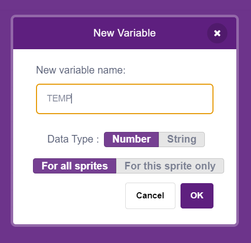
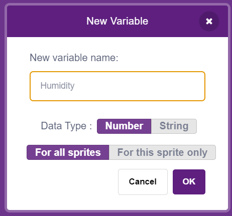
Go to the variable block palette & click on Make a Variable. Create two variables, Temperature & Humidity
Code
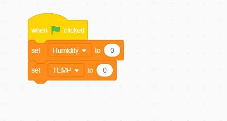
Add the "When Green Flag Click" block from the Event palette.
Set () variables to 0 from the variable palette.
Code
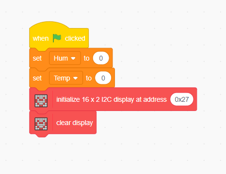
Add Initialize 16×2 I2C Display at address 0x27 block from Display palette
Add a Clear Display block.
Code
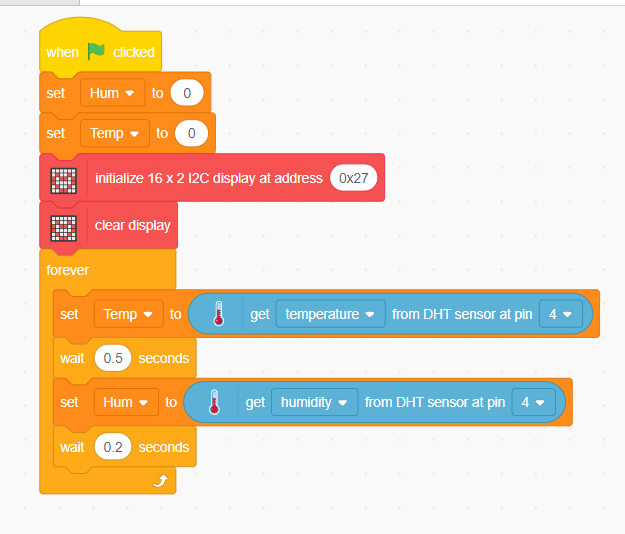
Inside a Forever loop:
Drag Set Temp to Temperature from DHT sensor at pin 4 from variable & Sensor palette respectively.
Add Wait 0.5 seconds from the Control palette
Set Hum to humidity from the DHT sensor at pin 4 from variable & Sensor palette respectively.
Wait 0.2 seconds from the Control palette
Code
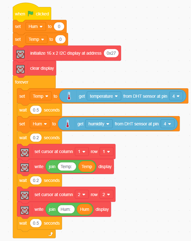
Display Temperature on LCD
- Set the cursor to Column 1, Row 1 block from the display palette
- Write: block from the display palette
- Add a join block from the operator palette and place it inside the Write block, and add Temp: [Temp]
- Wait 0.2 seconds.
Step 6: Display Humidity on LCD
- Set the cursor to Column 2, Row 2 from the display palette
- Write: block from the display palette
- Add a join block from the operator palette and place it inside the write block, and add Hum: [Hum]
- Wait 0.5 seconds.
Code
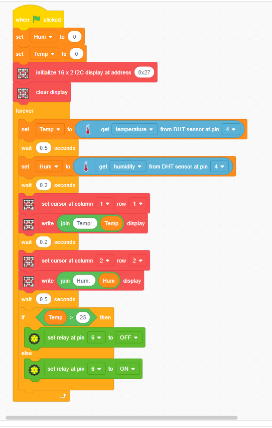
Control the Fan Using Relay
- Add an if-else block from the control palette and place it inside the forever block
If
Then:
Else:
Note: Many relay modules are Active LOW. In such modules:
- OFF = Relay Activated (Fan ON)
- ON = Relay Deactivated (Fan OFF)
Run
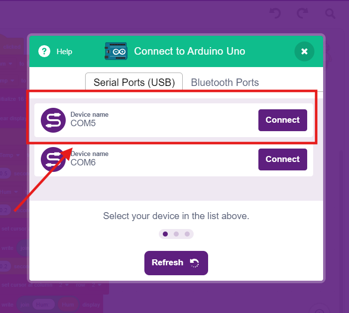
Connect your controller via the serial port and run the code