Smart Toll System With Web Integration
by SPLASH ELECTRONIC in Circuits > Arduino
189 Views, 1 Favorites, 0 Comments
Smart Toll System With Web Integration


.jpeg)

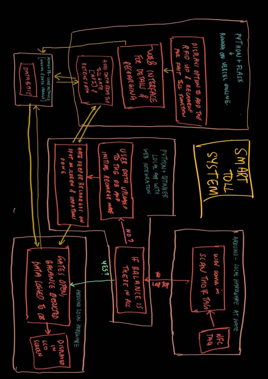
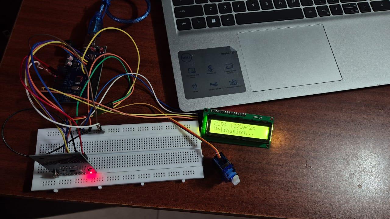
This is a SMART TOLL GATE SYSTEM WITH WEB INTEGRATION , this is a prototype project of a toll gate system where the user(vehicles) can scan their RFID cards for toll just like FAST-TAG in India , and then there will be a proprietary software in the toll booth for the authentication and new user creation.
CHECKOUT THE WEBSITE: checkout_website_now
CHECKOUT THE REPO : check_out_git_repository_of_project ( LegitCoconut )
- If the incoming vehicle don't has a vehicle pass ( RFID card ) , A new user account is created with the vehicle license number and a minimum recharge amount is got from the user, Toll amount is deducted and allowed to pass through the toll
- If the incoming vehicle has an account but don't has a minimum balance then a recharge prompt is shown and the card is recharged , Then money deducted and allowed to pass
- If the incoming vehicle has an account and also the minimum balance then , Toll amount is deducted and allowed to pass through the toll
All the user Details, Toll gate log are stored in an online instance of mongoDB for fast and reliable centralized acess. An online proprietary web page is also there to see the logs and recharge the account of users.
This project can be developed very much to introduce a centralized server for handling all the loads, Perfect user authenticated recharge portal and automatic user creation and A portal of the authorities to check the cash collected and other necessary data and AI models can also be introduced to take care of peak traffic hours by making vehicles according to their size go through different toll gates.
Supplies

Since this is an initial prototype, only fundamental components have been used. Advanced hardware options will be proposed in later stages of development.
The following components were used in the prototype:
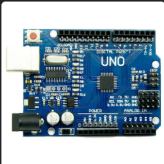
- Arduino® Uno
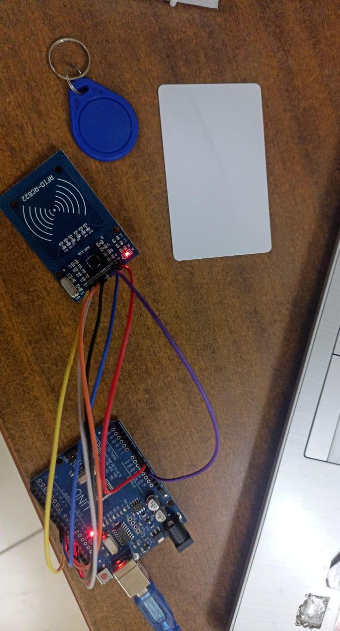
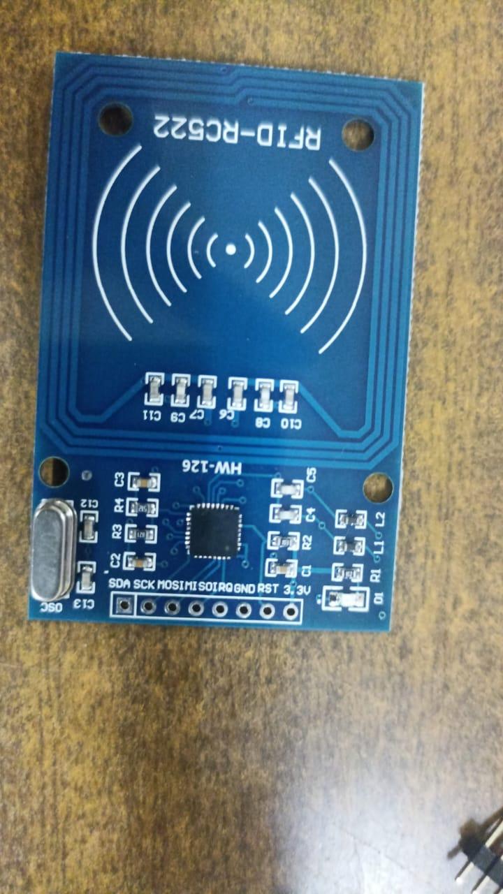
- RFID Reader (MFRC522) with Tags
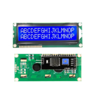
- 16×2 Liquid Crystal Display (LCD) with I2C Interface
- Servo Motor
- Breadboard and Jumper Wires
EXPLAINING WHAT ARE ALL THE USE OF THOSE COMPONENTS
- Arduino Uno as the brains of the system which can get the sensor data , display details in the LCD control the servo motor and all.
- RFID reader : every car will have a rfid card attached to the windshield or the driver can tap the rfid on the sensor , for getting the info about the car and the vehicle id and all.
- 16x2 LCD display: Act as a mode of communication with the driver or the user in the toll gate
- Servo Motor:
Downloads
SETTING UP THE HARDWARE CONNECTIONS
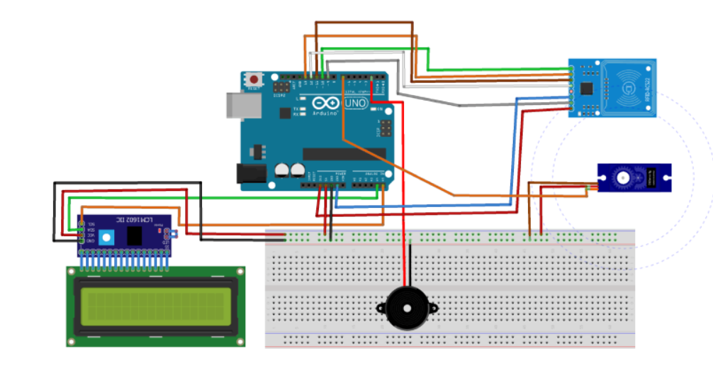

Please make sure that you power the system using the barrel jack with power source between 7v and 12v, use USB for only data transfer.
Connecting the RFID sensor
- VCC -> 3.3v ( only power from 3.3 else it will burn )
- GND -> GND
- RST -> D9
- MISO -> D12
- MOSI -> D11
- SCK -> D13
- SDA -> D10
Connecting the LCD screen
- VCC -> 5v
- GND -> GND
- SDA -> A4
- SCL -> A5
Connecting the Servo Motor
- VCC -> 5v
- GND -> GND
- SIGNAL -> D6
SETTING UP ARDUINO CODE
1. Library Inclusions
- Wire/I2C: For LCD communication via I2C.
- SPI: Required by MFRC522 RFID reader.
- MFRC522: Library to interact with the RFID module.
- Servo: For controlling servo gate movement.
2. Pin Definitions & Object Initialization
- SS_PIN, RST_PIN: Chip Select and Reset for RFID.
- SERVO_PIN: Servo PWM signal.
- mfrc522: Object to manage RFID functions.
- lcd: 16x2 LCD on I2C address 0x27.
- gateServo: Servo motor controller.
3. Setup Function
- Serial, SPI, RFID, LCD, and Servo initialized.
- LCD displays “Waiting for Toll” at startup.
- Useful for user feedback and debugging.
4. Main Loop – Card Detection & Handling
- Card polling logic.
- Returns if no card is present or can't be read.
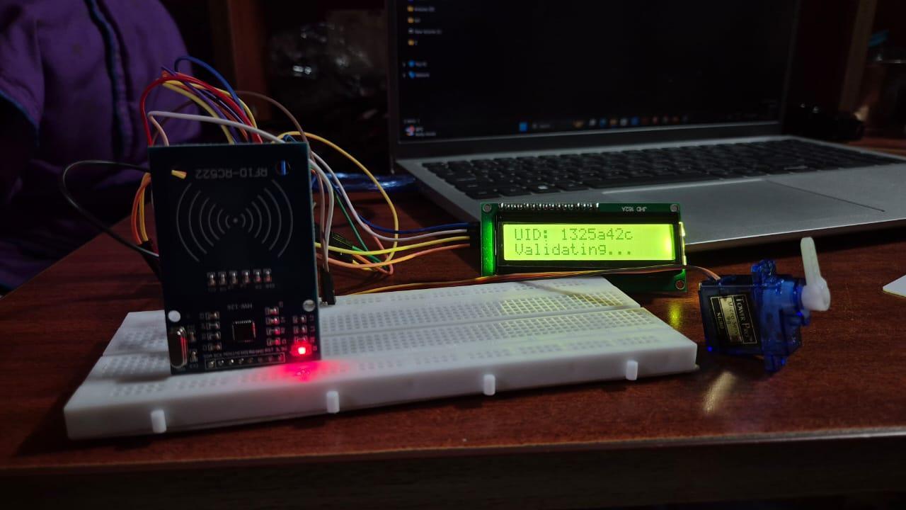
5. UID Reading and Sending
- Builds UID string from card's byte data (in HEX).
- Acts as a unique identifier.
- Displays UID and sends it to the laptop via Serial.
- Laptop is expected to handle backend validation.
6. Balance Reception from Laptop
- Waits for laptop to respond with the user’s balance.
- Reads and cleans the balance string.
- Balance is displayed on LCD.
7. Gate Control (Servo)
- Moves servo to open position for 2 seconds.
- Returns it to closed state after delay.
8. Reset System Display
- Waits and resets display for next RFID interaction.
⚙️ Overall Functionality (Summary)
This code creates a simple RFID-based toll authentication system:
- Detects RFID cards via MFRC522 module.
- Sends the UID to a connected laptop through the serial port.
- Laptop processes and returns balance info.
- Displays balance on an LCD screen.
- Controls a servo to simulate gate opening based on balance verification.
- Resets to standby after completing the operation.
It’s a closed-loop system where the Arduino handles I/O, while the laptop manages authentication logic.
Downloads
SETTING UP THE PYTHON SCRIPT
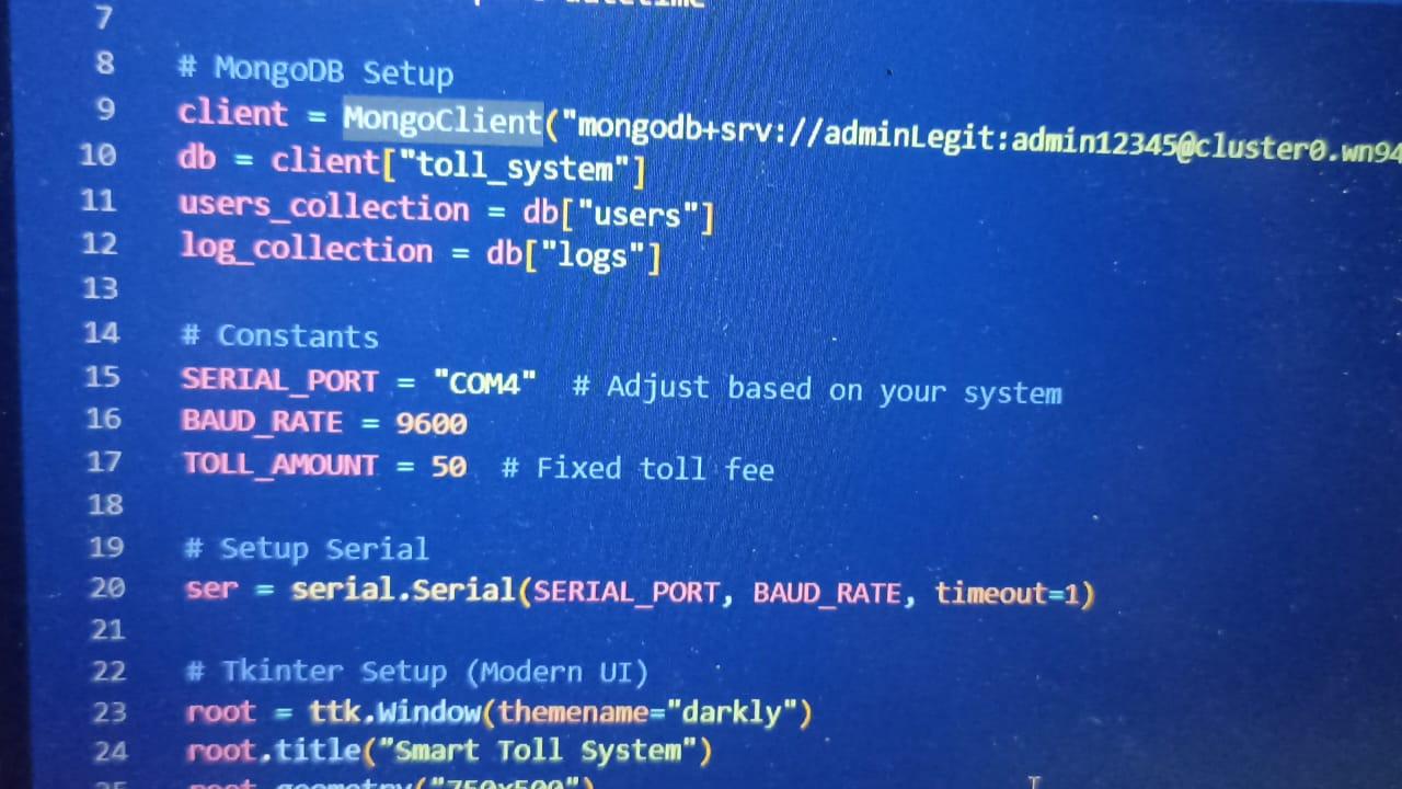

MAKE SURE TO CREATE AN MONGODB CLUSTER ONLINE AND CONNECT IT THERE
1. Data Input – UID from Arduino
- Arduino sends UID over serial (e.g., from an RFID card).
- serial_read() runs in a thread, continuously checks ser.readline() for incoming UID.
- Once UID is received, it's passed to process_uid(uid).
2. Processing UID
- handle_uid(uid) checks MongoDB (users_collection) for a document with that UID.
- Two cases:
- Existing user:
- Gets balance and vehicle from the user document.
- If balance >= TOLL_AMOUNT (50):
- Deduct toll: new_balance = balance - 50
- Update DB: set new balance.
- Add log to both global (log_collection) and user (logs array in user doc).
- Send new_balance back to Arduino via serial.
- Else:
- Show recharge form to recharge balance.
- New user:
- Show recharge form and ask for vehicle number.
3. Recharge Flow
- User enters recharge amount (and vehicle if new user).
- process_recharge(...):
- Validates input.
- If new user:
- Create a document with:
- uid, vehicle, balance = amount - 50, and empty logs list.
- If existing user:
- Add amount to balance, deduct 50, update balance in DB.
- Add a log entry.
- Send new_balance to Arduino via serial.
4. Logs Handling
- update_log(uid, vehicle, message):
- Creates a log entry with time and event.
- Adds it to:
- logs array in user document.
- log_collection (global logs).
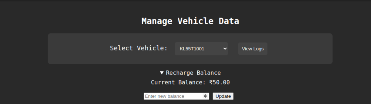
- Logs are shown in:
- Logs tab: All entries from log_collection, newest first.
- Vehicle Logs tab: Fetches logs of selected vehicle from user's logs array.
5. Vehicle Dropdown
- Periodically (every 5 seconds), load_vehicle_dropdown() pulls all vehicle numbers from users_collection and updates the dropdown list in UI.
6. Final Output to Arduino
- After processing, send_to_arduino(balance) sends the current balance back to Arduino as bytes.
Summary:
- Input: UID from serial → check DB.
- Process:
- If user exists → check balance → deduct toll if enough.
- Else → prompt for recharge/new user.
- Output: Updated balance to Arduino, logs to DB, updates in UI.
Downloads
SETTING UP THE WEBPAGE


To setup the web page, fork the project_repo and make an account on vercel for hosting the web-page, and import the repo onto vercel, then while deployment add username , password and the MongoDB URI as environmental variables and then deploy the web page.
for more info on how to setup the web page visit the GitHub repo
THE PROJECT IS COMPLETE

If you see there need to be more improvements in the projects fork the repo and make all the chnages and make a pull request
fell free to put out sugestions