Soft-Start and Soft-Finish for P-Channel MOSFETs
by Psilocybin in Circuits > Electronics
870 Views, 0 Favorites, 0 Comments
Soft-Start and Soft-Finish for P-Channel MOSFETs

Sudden power surges can fry components in high-voltage circuits, while abrupt shutoffs cause voltage spikes that disrupt performance. For my high-voltage (HV) coil project, I needed a soft-start circuit to gradually ramp up power and a soft-finish circuit to smoothly power down, shaping a 31 kHz waveform without oscillations or “ringing.” Most soft-start circuits for P-channel MOSFETs were designed for slow, one-shot applications like lighting, not high-frequency switching. After scouring the web and finding no suitable designs, I invented my own, adapting an N-channel circuit from Texas Instruments’ E2E forums.
This Instructable shares a simple, elegant soft-start/soft-finish circuit using P-channel MOSFETs (e.g., IRF9540, IRFP9240), resistors, potentiometers, and diodes. It’s perfect for HV coils, motor drivers, audio amplifiers, or any project needing clean power transitions. With recent updates adding silicon carbide (SiC) diodes to dampen signal spikes, this circuit is both robust and versatile. Follow along to build it, tweak it, and see the results on your oscilloscope!
Supplies
Here’s what you’ll need to build the soft-start/soft-finish circuit:
- Power Supply: 12 VDC (for testing; adjust for your project’s voltage, up to 100V for IRF9540 or 200V for IRFP9240).
- Oscilloscope: To observe waveform changes (e.g., soft-start and soft-finish effects).
- P-Channel MOSFET (1x): I used the IRF9540 (Vds = -100V, Id = -19A, TO-220 package) for development. Alternatives: IRF9640 (-200V, TO-220), IRFP9240 (-200V, TO-247AC). Source from Amazon, eBay, or DigiKey (beware of counterfeits from unverified sellers).
- Potentiometers (2x): 5 kΩ variable resistors to adjust soft-start and soft-finish timing. Available on Amazon.
- Resistors:
- 2x 330 Ω (1/2 W, backstop for potentiometers; minimum 288 Ω at 12 VDC, calculated as R = V²/W = 12²/0.5).
- 1x 47 Ω (for gate resistor).
- Optional: 1x 4.7 kΩ (for power-ON LED).
- Diodes:
- 1x UF4007 (ultra-fast, 1000V, to prevent the gate driver totem-pole from draining the MOSFET gate).
- 2x D10S120 SiC Schottky diodes (1200V, <10 ns response, for spike damping; optional but recommended).
- Solderless Breadboard: For prototyping.
- Wire: 22 AWG for connections.
- Connector Blocks: 1x small (for TO-220 MOSFETs) and 1x large (for TO-247 MOSFETs).
- Optional: LED (for power indication), grounding strap (to prevent electrostatic discharge).
- Signal Source: A 31 kHz pulsed DC signal, generated using my Instructable, “A Way-Better Variable-Frequency PWM Using Two TLC555 Timers (or One TLC556).” Amplify and protect your MOSFET with a gate-driver IC (e.g., MC34152P).
Note: For other frequencies (e.g., 10 kHz or 50 kHz), adjust resistor values—lower resistance for higher frequencies, higher for lower. Experiment to optimize.
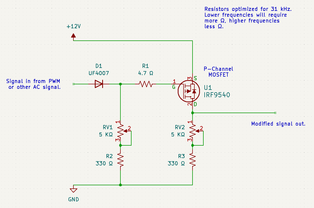
How the Circuit Works
This circuit softens the on/off transitions of a P-channel MOSFET at 31 kHz, reducing inrush current (sudden power surges) during startup and ringing (waveform oscillations) during shutdown. It adapts a Texas Instruments N-channel design, replacing a PNP transistor with a P-channel MOSFET to handle high frequencies without overheating. Here’s the breakdown:
- Soft-Start (Gate Control):
- A UF4007 diode isolates the gate-driver IC (MC34152P) from the MOSFET’s gate, preventing the IC’s totem-pole output (its push-pull stage) from draining the gate’s internal capacitance.
- A 47 Ω gate resistor and a 5 kΩ potentiometer (with a 330 Ω backstop) slow the charging of the gate capacitor, creating a gradual turn-on (~100–500 µs). This limits inrush current, visible as a smooth rise in the gate signal (yellow trace on oscilloscope).
- Adjusting the left potentiometer tunes the soft-start timing.
- Soft-Finish (Drain Control):
- A second 5 kΩ potentiometer (with 330 Ω backstop) on the MOSFET’s drain slows the turn-off, softening the output waveform (blue trace) to prevent voltage spikes.
- Adjusting the right potentiometer controls the discharge rate, minimizing ringing in high-frequency applications like HV coils.
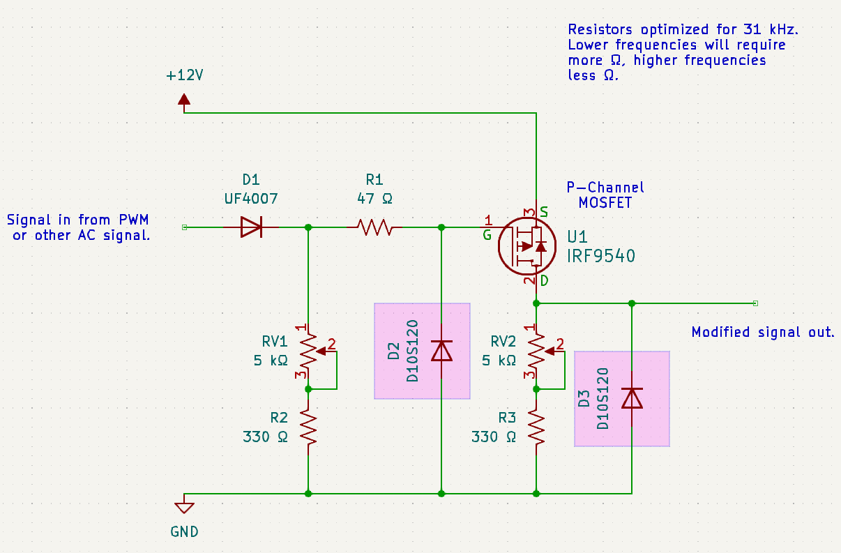
- Spike Damping:
- Two D10S120 SiC Schottky diodes (1200V, <10 ns) clamp ~2V spikes on the gate and output signals to ground. The gate diode connects between the gate-resistor junction and ground; the output diode ties the drain output to ground. This ensures cleaner waveforms.
Technical Notes:
- MOSFET Choices: Use IRF9540 for loads up to 100V or IRFP9240 for up to 200V. Both are avalanche-rated, handling inductive spikes safely (see MOSFET Avalanche explanation below).
- Frequency: Designed for 31 kHz, but adjustable. Lower frequencies need higher resistance (e.g., 10 kΩ potentiometers); higher frequencies need lower (e.g., 2 kΩ).
- Inspiration: Adapted from TI’s “Effects of Gate RC Soft Start” (E2E forums), with a P-channel MOSFET for high-frequency robustness.
Assemble Your Components


Before handling the MOSFET, ground yourself to prevent electrostatic discharge (ESD), which can destroy sensitive electronics. I use a copper foil connected to Earth ground, placing my bare foot on it.
Components:
- 2x 330 Ω resistors
- 1x 47 Ω resistor
- 2x 5 kΩ potentiometers
- 1x UF4007 diode
- 2x D10S120 SiC diodes (optional)
- 1x P-channel MOSFET (IRF9540 or IRFP9240)
- 1x connector block (small for TO-220, large for TO-247)
Note: The connector block protects the breadboard from large MOSFET pins. For TO-247 MOSFETs (e.g., IRFP9240), use a larger block.
Prepare Your Components


To avoid short circuits, trim component leads to ~6 mm using a tagboard template or ruler. I trim the resistors and leave the diode, potentiometers, and MOSFET leads intact.
For the smaller MOSFET:
- Bend ~6 mm of each lead (Gate, Drain, Source) away from the front at a 90° angle.
- Twist the outer leads (Gate, Source) outward by ~5° to fit the connector block.
- Insert the MOSFET into the block, tighten the screws, and set aside for breadboard insertion.
Note: I use the IRF9540 (TO-220) here, but the IRFP9240 (TO-247) works similarly with a larger connector block. There is no need to twist the outer leads of the larger MOSFET.
Your components are now all prepared. We will go to the next step.
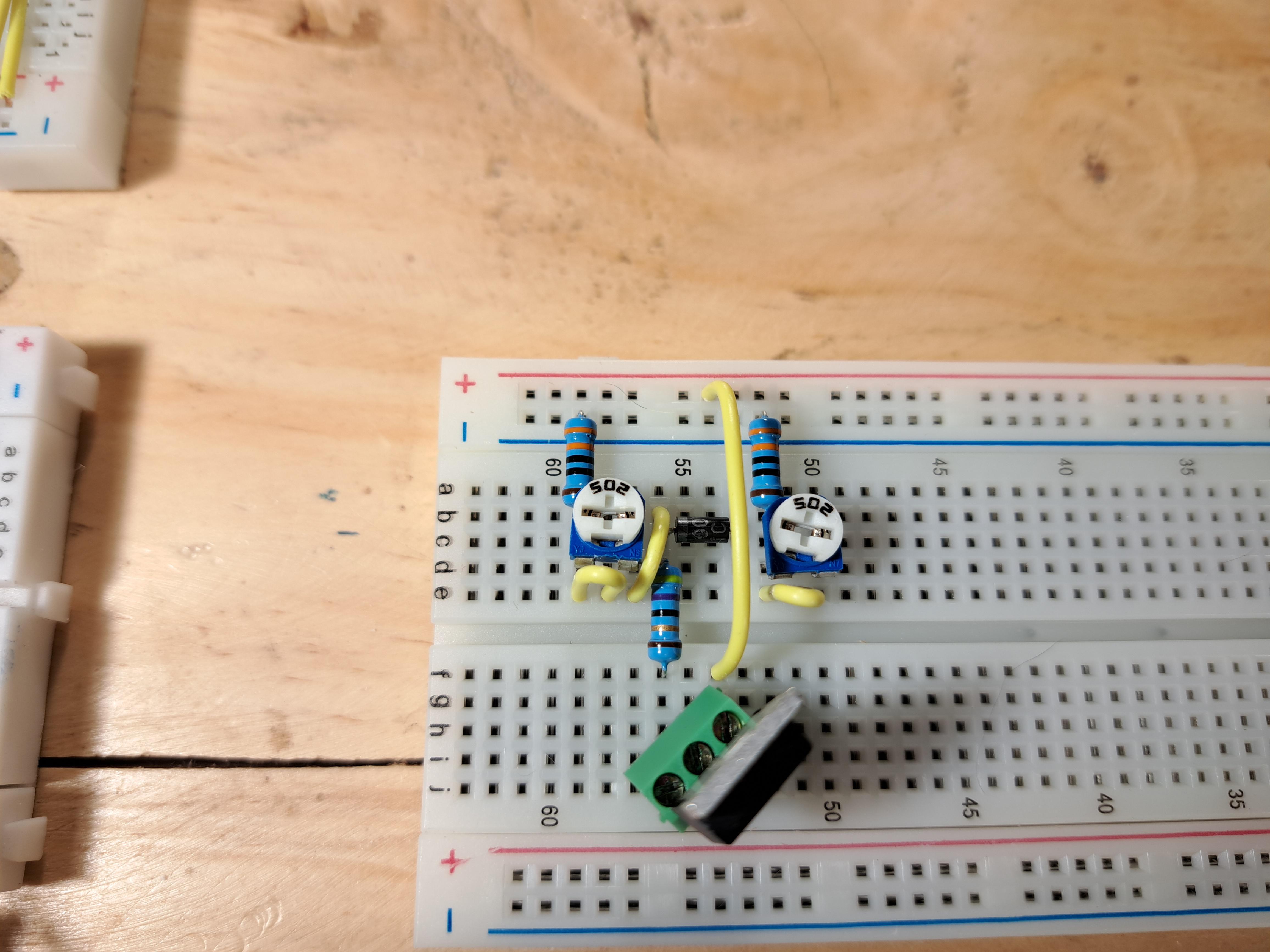
Assemble the Breadboard


Place components on the solderless breadboard carefully:
- Power Rails:
- Connect upper and lower power rails with two wires (red for +12 VDC, blue for ground).
- Resistors:
- Place two 330 Ω resistors from the ground rail (-) to the left pin of each 5 kΩ potentiometer.
- Place the 47 Ω resistor across the breadboard’s central channel, aligning with the MOSFET’s gate pin later.
- Diodes:
- Insert the UF4007 diode, cathode (banded end) in the same column as the 47 Ω resistor’s upper end, anode (unbanded end) for the signal input.
- Place two D10S120 SiC diodes: one from the gate-resistor junction to ground (cathode to gate), one from the output wire to ground (cathode to output).
- Potentiometers:
- Place both 5 kΩ potentiometers, ensuring the left pin connects to the 330 Ω resistor and the right pin will connect to wires.
- MOSFET:
- Insert the connector block with the MOSFET diagonally, aligning the gate pin (left) with the 47 Ω resistor’s column. Check the datasheet for pinout (Gate, Drain, Source).
Tip: Label the breadboard or use colored wires to avoid confusion.
Now we are going to place the wires into the board.
Wire the Breadboard


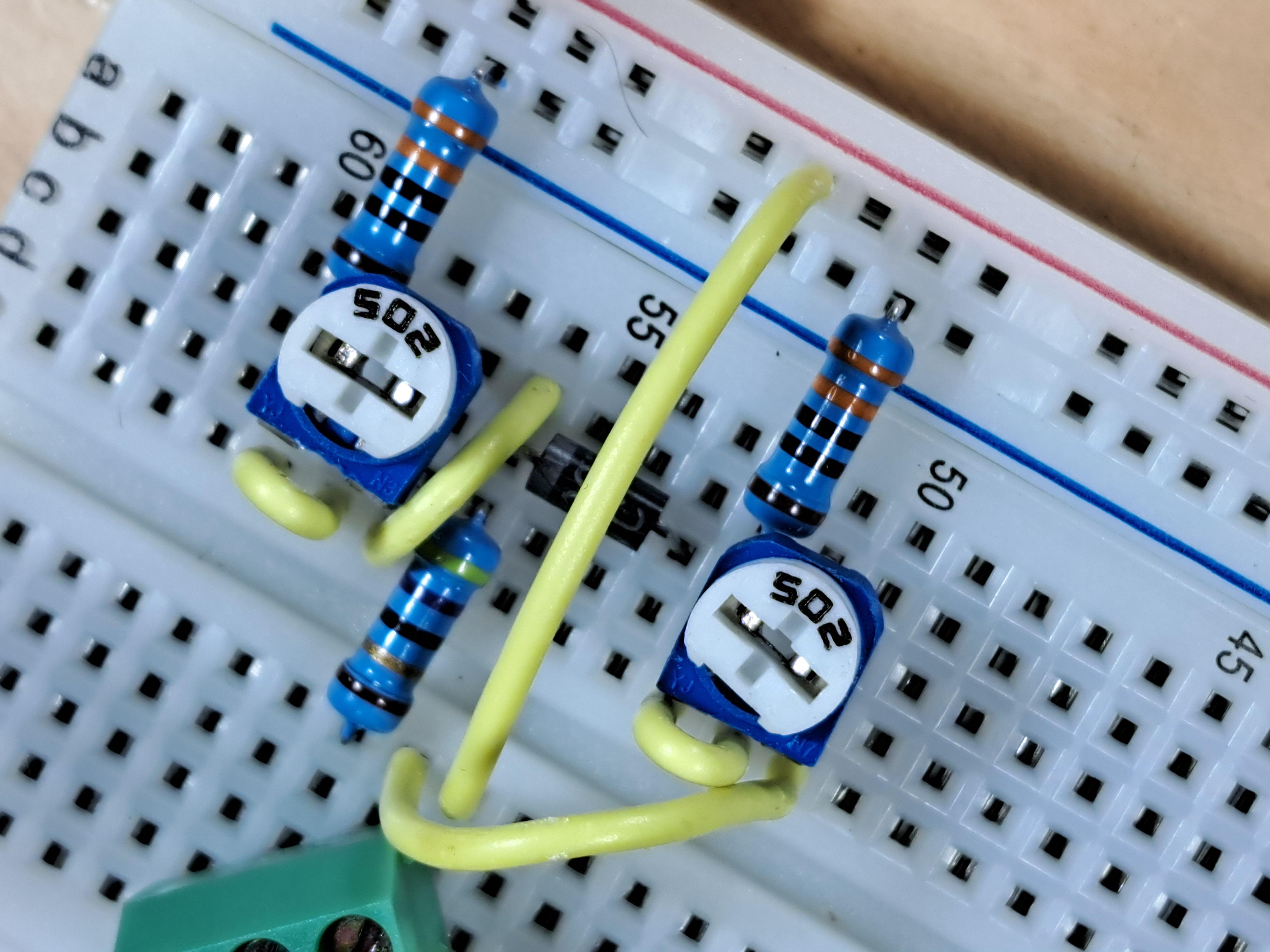

Add five internal wires to complete the circuit:
- Potentiometer Links:
- Connect pins 1 and 2 of each potentiometer with a wire, turning them into variable resistors.
- Power to MOSFET:
- Wire the +12 VDC rail to the MOSFET’s Source (pin 3, right).
- Gate Discharge:
- Connect the junction of the UF4007 diode’s cathode and 47 Ω resistor to the right pin of the left potentiometer. This drains the gate capacitor for soft-start.
- Output Path:
- Wire the MOSFET’s Drain (pin 2, middle) to the right pin of the right potentiometer. This is the circuit’s output, where power and signal exit.
- Optional Power-ON LED:
- Connect the LED’s anode to the +12 VDC rail, cathode to a 4.7 kΩ resistor, and the resistor to ground (order doesn’t matter).
External Connections:
- Connect +12 VDC to the red rail, ground to the blue rail.
- Feed a 31 kHz pulsed DC signal (from the TLC555/TLC556 circuit via MC34152P gate-driver) to the UF4007 diode’s anode.
Test and Adjust the Circuit


Connect an oscilloscope probe to the breadboard column with the right potentiometer’s pin 3 (MOSFET Drain output) to observe the modified waveform.
- Baseline:
- Set both potentiometers to 0 Ω (minimum resistance).
- Observe the output (blue trace) and gate input (yellow trace) on the oscilloscope. The blue trace is inverted due to P-channel MOSFET behavior (high gate signal = low output).
- Soft-Start:
- Adjust the left potentiometer (0–5 kΩ). The blue trace’s rising edge smooths, showing reduced inrush current (see Photos 2–4).
- Soft-Finish:
- Adjust the right potentiometer (0–5 kΩ). The blue trace’s falling edge softens, minimizing ringing (see Photos 5–6).
- Spike Damping:
- The D10S120 SiC diodes clamp 2V spikes on the gate and output, ensuring clean signals (visible in updated circuit).
Tip: For frequencies other than 31 kHz, tweak resistors (e.g., 2 kΩ for 50 kHz, 10 kΩ for 10 kHz) and monitor with the oscilloscope.
Downloads
Conclusion


This soft-start/soft-finish circuit transforms 31 kHz waveforms for P-channel MOSFETs, eliminating inrush current and voltage spikes in high-voltage projects like my HV coil. Using IRF9540 or IRFP9240 MOSFETs, resistors, potentiometers, and fast diodes (including SiC Schottky diodes for spike damping), it’s a low-cost, reliable solution for clean power switching. Its simplicity and flexibility make it ideal for HV coils, motor drivers, audio amplifiers, or any circuit needing smooth transitions.
Build it, tweak the potentiometers, and watch the waveform magic on your oscilloscope! Share your builds, modifications, or questions in the comments—I’d love to see how you use it. If you find this Instructable helpful, give it a Heart (Favorite). For errors or suggestions, drop me a comment to keep improving this design.
Credit: Special thanks to Grok, created by xAI, for editorial assistance in polishing this Instructable’s clarity and flow.