Soil Moisture & Weather-Forecast Based Smart Watering System
by foxtrap in Circuits > Electronics
854 Views, 11 Favorites, 0 Comments
Soil Moisture & Weather-Forecast Based Smart Watering System
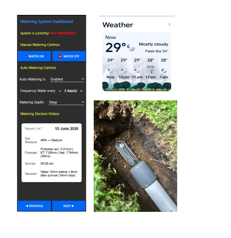
This project details the construction of a smart watering system that saves water and a non-trivial amount of money. It uses a combination of parameters such as time of day, soil moisture, forecast rainfall, probability of rainfall, and forecast evapotranspiration rates to decide how much water to give my garden.
For the smart component of the system I used a Wrapit-Solutions starter kit, which uses a Raspberry Pi Zero 2W as a hub and an ESP8266 as a sensor interface. This system comes pre-equipped with NodeRed, which enabled me to implement the logic of the project as a flow that requests weather forecast data from open-meteo, reads soil moisture content from a sensor installed in my garden and controls the watering system.
Supplies
- 1x Wrapit-Solutions Starter Kit which includes a Raspberry Pi hub and an ESP8266 based sensor interface board
- 1x 12 Volt DC (24 Volt DC would also be fine) Normally Closed Water Solenoid Valve
- 1x 220VAC/12VDC (or 24VDC) Power adaptor with suitable current capability to drive the solenoid valve
- 1x Soil Moisture Sensor (Capacitive) e.g. DFRobot SEN0193
- 2x 10k Ohm ¼ watt resistors
- 15 ml of epoxy glue (e.g. Araldite)
- 1x 32mm (1.25”) poly pipe end cap
- 1x 4 metre length of 32mm poly pipe (or more as required)
- 2x 32mm 90° poly pipe connectors (or more as required)
- Suitable data cable, e.g. 3 conductor shielded 22-24 AWG or cat 5 or cat 6
- 1x Tipping Bucket Rain Gauge (optional)
- 1x rain gauge mount and poly pipe for rain gauge cabling (optional)
A Word on Sensors
I used a capacitive rather than resistive moisture sensor due to the fact that resistive sensors tend to corrode and exhibit unreliable behaviour. The active elements in the capacitive sensors are lined with a clear coating that inhibits corrosion. This is not the case for resistive probes as they work on the principle of measuring the changing resistance with moisture and therefore need to be in direct contact with the soil. Unfortunately this leads to unreliable behaviour and makes them unsuitable for long term use.
Hardware Connections
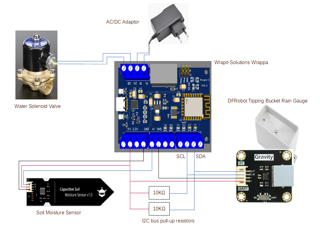
The diagram above depicts the interconnections between the various hardware components of the system. Note: The DFRobot tipping bucket rain gauge is an optional extra and is not an essential project component. I included it in my project simply because I wanted to compare how much rain had actually fallen at my location in the last 24 hours versus Open-Meteo’s forecast rainfall.
- The AC/DC adaptor (12-24Vdc) for powering the solenoid connects to Wrappa relay contacts 1A and 1BNote 1
- The water solenoid valve connects to Wrappa relay contacts 2A and 2BNote 1
- The ‘D’ (SDA) output of the tipping bucket rain gauge connects to the Wrappa terminal D2Note 2
- The ‘C’ (SCL) output of the tipping bucket rain gauge connects to the Wrappa and D3Note 2
- The ‘-’ output of the tipping bucket rain gauge connects to the Wrappa GND terminals
- The ‘+’ output of the tipping bucket rain gauge connects to Wrappa 3.3V terminal
- ‘+’ of the soil moisture sensor connects to the Wrappa 3.3V terminal
- ‘-’ of the soil moisture sensor connects to a Wrappa GND terminal
- ‘A’ of the soil moisture sensor connects to the Wrappa A1 terminal
- A 10k Ohm I2C bus pull-up resistor is connected between the Wrappa 3.3V terminal and the Wrappa D2 terminal
- A 10k Ohm I2C bus pull-up resistor is connected between the Wrappa 3.3V terminal and the Wrappa D3 terminal
- If shielded data cable is used for either the sensor or the rain gauge, terminate the shield on the Wrappa GND terminal. Leave it open at the other end
Note 1: polarity is not important
Note 2: Terminals D2 and D3 need to be configured as the Wrappa’s i2c bus using a Wrappa Manager node in the flow
The Logic - Inputs & Assumptions
The hub in the Wrapit Solutions starter kit runs an instance of Node-RED as its programmable logic driving engine but before getting into the Node-Red flow, which is effectively the ‘brains’ of the watering system, it’s worth having a quick look at the factors one might choose to consider in any non-trivial attempt to save on water usage/costs.
Water Use Logic
It’s important to recognise that truly optimising water consumption can be a pretty complicated business. Here are just some of the factors to consider for a residential home scenario: forecast sun, wind and rain; forecast reliability (i.e. forecast probabilities); the water requirements and absorption rates of your target plants/trees/grasses; available water pressure; the time of day to water; actual temperature, wind, humidity throughout the day; the characteristics of your chosen water delivery mechanism (drip, sprinkler, soaker hose etc.); soil absorption/drainage characteristics; the garden’s exposure to sun/shade/wind; lawn/garden topology and susceptibility to runoff; whether there are requirements for a lawn or garden to be dry at any particular time(s) of the day; yours and your neighbours tolerance for any sounds emitted by your watering system early in the morning; the cost of water, etc. etc.
In this project I didn’t try to ‘boil the ocean’ by incorporating too many water usage optimisation factors, instead I simply sought to establish a sensible balance between complexity and efficacy. As such, I chose the following factors for this project: time of day to water; soil moisture; and a forecast of rainfall, rainfall probability and evapotranspiration rates. With these factors, along with a one-time moisture sensor auto-calibration effort, and by making a small number of parameter settings in a Node-RED flow, my claim is that this project represents a fairly effective smart watering optimisation solution.
So here’s the logic: Every night at just past midnight the system ‘wakes up’ and determines whether it’s a watering day, if not, it goes back to sleep. If watering is scheduled for the current day, we make a call to the website sunrise-sunset.org to obtain a time for sunrise. Once we have a time for sunrise, we set a timer to trigger activities at a predefined time before sunrise. Note: watering just before and just after sunrise is generally considered the best time for watering your garden because: it’s cooler; there’s usually less wind and therefore evaporation; and plants are ‘waking up’ and absorbing water in preparation to photosynthesise during daylight hours. When the timer triggers, we:
- Take a soil moisture reading
- Obtain an hour by hour forecast of precipitation, precipitation probability, and evapotranspiration rates from the Meteo website
- Use the current soil moisture measurement and the forecast data from Meteo to calculate a watering duration
- Water for half of the calculated duration before sunrise and the other half after sunrise
Implementing the Logic With Node-Red
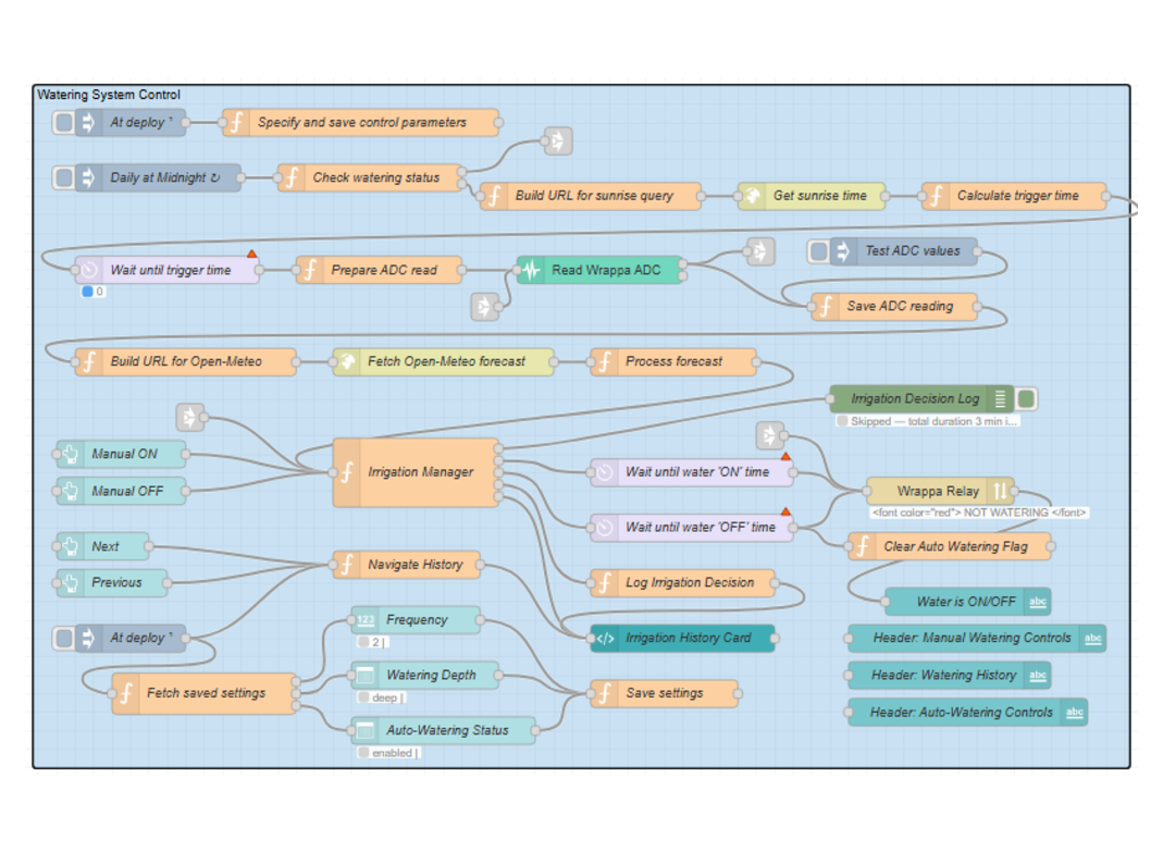
The figure above is a screenshot of the Node-RED flow (available on GitHub) that implements the aforementioned logic. I freely admit that in constructing this project I used AI – Anthropic’s Claude – to create the flow from scratch. Claude made some reasonable suggestions and did eventually come up with a reasonably decent flow, but in the process it made quite a few errors, often generated overly complex or convoluted code, and made a lot of incorrect assumptions, so it took a good number of iterations and more detailed revised prompting and specifying requirements to get it going.
The flow may look a little intimidating but it’s actually not too complicated. Here’s a short description of how it works: The ‘At deploy’ inject node and ‘Specify and save control parameters’ function node at the top left of the flow combine to support the specification and saving of system control parameters, including the local timezone and the latitude/longitude of the watering system.
The ‘Daily at Midnight’ inject node runs at 1 minute past midnight every night. When it does, it triggers the ‘Check watering day’ function node which determines whether or not it’s a watering day. Note: the watering frequency is specified using the flow’s dashboard (see below). Assuming it’s a watering day, the ‘Build URL for sunrise query’ function node constructs a request URL which the ‘Get sunrise time’ HTTP node sends to the sunrise-sunset.org website. The response from sunrise-sunset.org contains the time for sunrise which the ‘Calculate trigger time’ function node converts to a delay period. The delay period is then sent to the ‘Wait until trigger time’ delay node.
When the trigger time comes around, the ‘Prepare ADC read’ function node triggers a single ADC (analogue in) read by the Wrappa. The raw ADC value returned by the Wrappa is saved by the ‘Save sample’ function node which also triggers the ‘Build URL for Open-Meteo’ function node. That node constructs a forecast query which is sent to the Open-Meteo website by the ‘Fetch Open-Meteo forecast’ node. The response from Open-Meteo contains an hour by hour forecast of rain, probability of rain, and evapotranspiration rates which the ‘Process forecast’ function node aggregates and sends to the ‘Irrigation Manager’. The irrigation manager node makes an irrigation decision based on: calibration data (see below); the saved soil moisture reading; and all the forecast information from Open-Meteo. Note: under certain soil moisture and weather forecast conditions the ‘Irrigation Manager’ may decide to skip watering altogether.
After the irrigation decision is made for the current day, the irrigation manager node then controls switching the watering system on and off via the ‘Wrappa Relay’ node.
The collection of nodes at the bottom of the ‘Watering System Control’ flow supports logging irrigation decisions and the construction of the system’s user interface or dashboard (see below).
The Dashboard
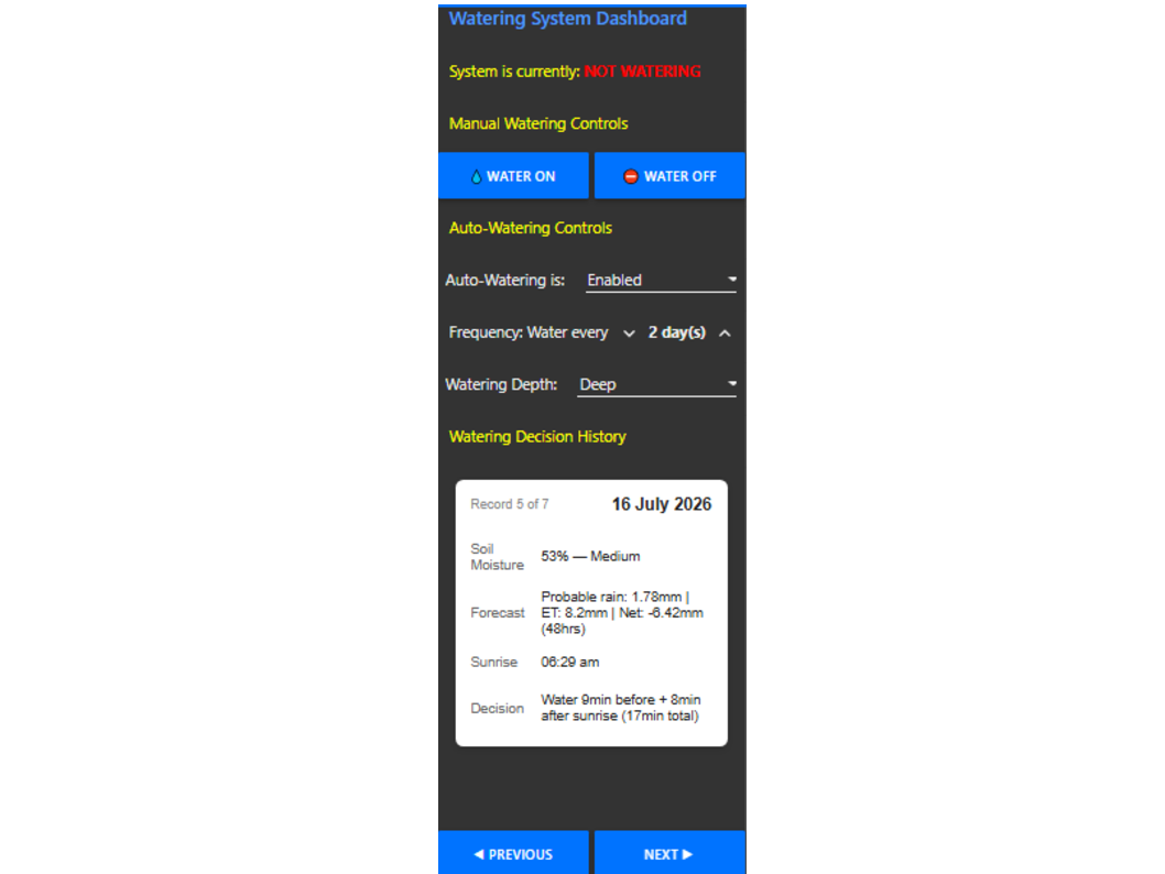
The Node-Red dashboard produced from this flow provides watering information and control options, as shown in the image above.
- The status is presented by the ‘System is currently’ field at the top of the dashboard, which indicates whether the system is currently watering or not.
- The ‘Manual Watering Controls’ buttons act as an over-ride to manually turn the watering system on or off.
- The ‘Auto-Watering Controls’ supports:
- enabling and disabling auto-watering (useful for seasonal control);
- specifying the number of days between auto-watering attempts; and
- specifying the auto-watering depth (light, moderate, deep).
- The ‘Watering Decision History’ provides visibility into watering decisions for the last 7 days.
Installing the Soil Moisture Sensor
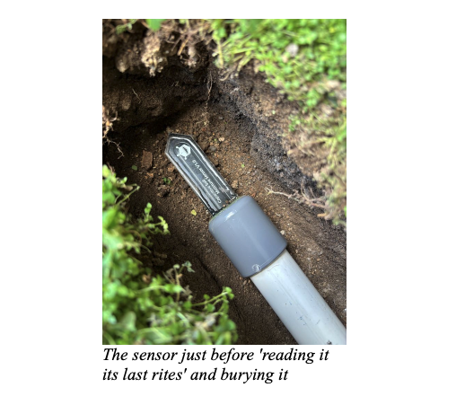
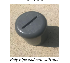
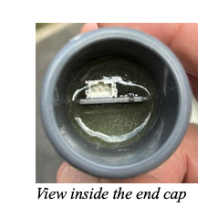
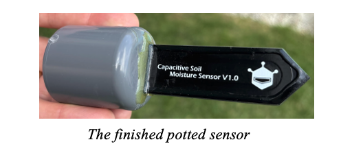
The soil moisture sensor is a critical element in this project so a little effort is necessary to prepare and install it appropriately. Here’s how I did it (Note: this doesn’t mean it’s the best or only way to do it, but it worked for me). I used a 2mm drill to create a line of holes in a 32mm poly pipe end cap. I then used small rat tail and flat files to create a slot in the end cap. I made sure to make the fit between the moisture sensor and the end cap reasonably tight so the epoxy didn’t bleed excessively out of any gaps between the two. The slot also needs to be centred so there’s sufficient clearance between both sides of the sensor when the poly pipe is inserted into the cap.
I then ‘potted’ the sensor in the cap using a two part epoxy resin. Note that I also put some epoxy on the edges of the sensor to reduce the risk of the printed circuit board delaminating when exposed to a moist environment for a long time.
I chose to install the sensor under my lawn at a depth of about 10cm. Note the orientation of the sensor, with the capacitor electrode tracks of the sensor facing upwards. My thinking was that the weight of the soil above the sensor would ensure reasonably good contact between soil and sensor under most, if not all soil moisture conditions. Time will tell whether this was a sensible decision or not.
Initial System Verification
Once the probe was installed under the lawn and connected to the Wrappa, and the solenoid valve was connected in line with my outside tap and lawn/garden sprinkler system, I was able to verify connectivity and proper functioning of the setup before starting the calibration. I used the manual controls on the dashboard to turn on/off the watering system. I also inserted a temporary inject node in the flow and connected its output to the ‘Read Wrappa ADC’ node to verify I was getting a sensible signal from the moisture probe.
Calibrating the System
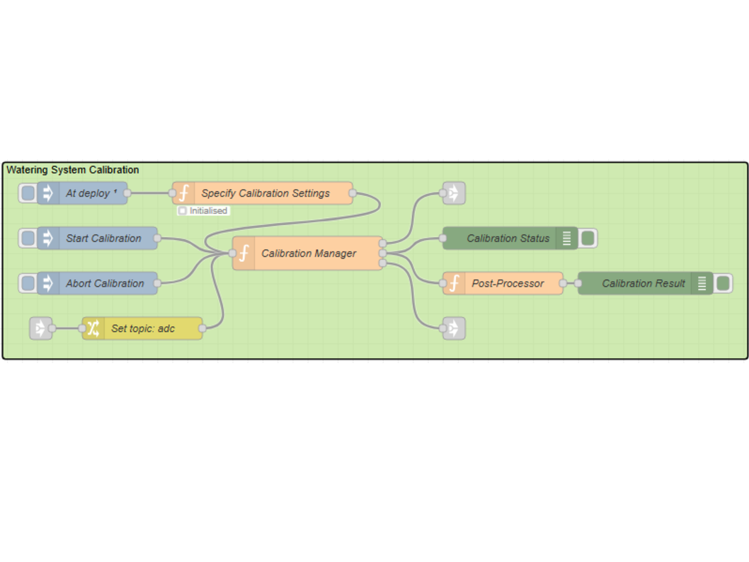
For the system to work effectively in its particular environment, a one-time calibration is required (or more than once if soil/sensor conditions materially change). Here’s the calibration process:
1. Install the soil moisture sensor in its intended long term location and ideally leave it for a few days to bed in
2. Allow the target lawn/garden to dry out for several days. The soil needs to be nice and dry before performing the calibration.
3. Make sure the debug panel on the Node-RED design centre is visible
4. Run the ‘Watering System Calibration’ flow above by clicking on the left of the ‘Start Calibration’ inject node. Calibration results will start appearing in the debug panel.
5. Wait for the calibration completed message in the debug panel (depending on the permeability of your soil, this could take more than 30 minutes)
6. Tweak calibration parameters in the ‘Specify Calibration Settings’ node if the calibration is unsuccessful. How parameters affect calibration is explained in the ‘Tuning the System’ section below and also in comments in the node’s code
Tuning the System
The system parameter settings I used for my lawn/garden will not be suitable in all circumstances, so with this in mind, a number of system control parameters have been exposed and can easily be changed. The key parameters in the “Specify and Save Control Parameters” node are:
- Timezone: Ensures correct conversion from UTC sunrise time to local time. Also takes into account daylight savings where applicable
- Latitude/Longitude: Your location for the correct Open-Meteo forecast
- Light and moderate watering duration percentages: These parameters specify a watering duration as a percentage of the calibrated deep watering duration.
- Light, moderate, and deep rainfall in mm: These specify rainfall equivalent in mm for each watering intensity
The key parameters used in calibration are:
- BASELINE_SAMPLES: Count of samples used to establish a stable ‘dry’ baseline.
- SAMPLE_INTERVAL_MS: Interval between ADC samples throughout the various phases of calibration (in milliseconds)
- BASELINE_DEVIATION_MAX: Maximum allowable deviation of any baseline sample from the baseline mean. If any sample during the ‘dry’ baseline phase of calibration exceeds this, calibration aborts with an unstable baseline error.
- TOO_WET_THRESHOLD: ADC value at or below which soil is considered too wet to calibrate. Calibration aborts if the baseline mean is at or below this value
- SATURATION_DELTA: Used for saturation detection – if ADC values change by less than this for a number of consecutive samples, the soil is deemed saturated.
- SATURATION_WINDOW: The number of consecutive samples required to confirm saturation.
- CALIBRATION_TIMEOUT_MS: Maximum total calibration duration (milliseconds) before a soft timeout occurs.
These key parameters can be modified in the ‘Specify Calibration Settings’ node.
The NodeRed Flow is available on GitHub and it should be a simple exercise of downloading it and simply hitting deploy in NodeRed. I hope you enjoy it and save lots of water and maintain a healthy lawn and garden.