SolMate 2.0
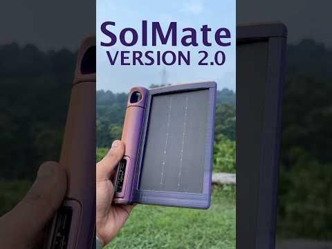
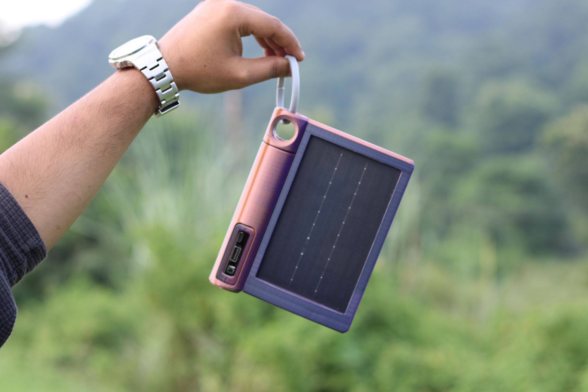
Greetings, everyone! This is SolMate 2.0, an updated version of my original SolMate project.
SolMate is a compact solar power bank that clips onto the back of your backpack and charges your devices while you're on the go. It's built as a simple trekking companion for hikers, travelers, and outdoor enthusiasts.
The device uses a 2W high-efficiency PTFE solar panel, capable of supplying up to 5V at 400mA under suitable sunlight conditions. The solar panel charges a 2200mAh Li-ion battery, which can then be used to power your phone or other small USB devices.
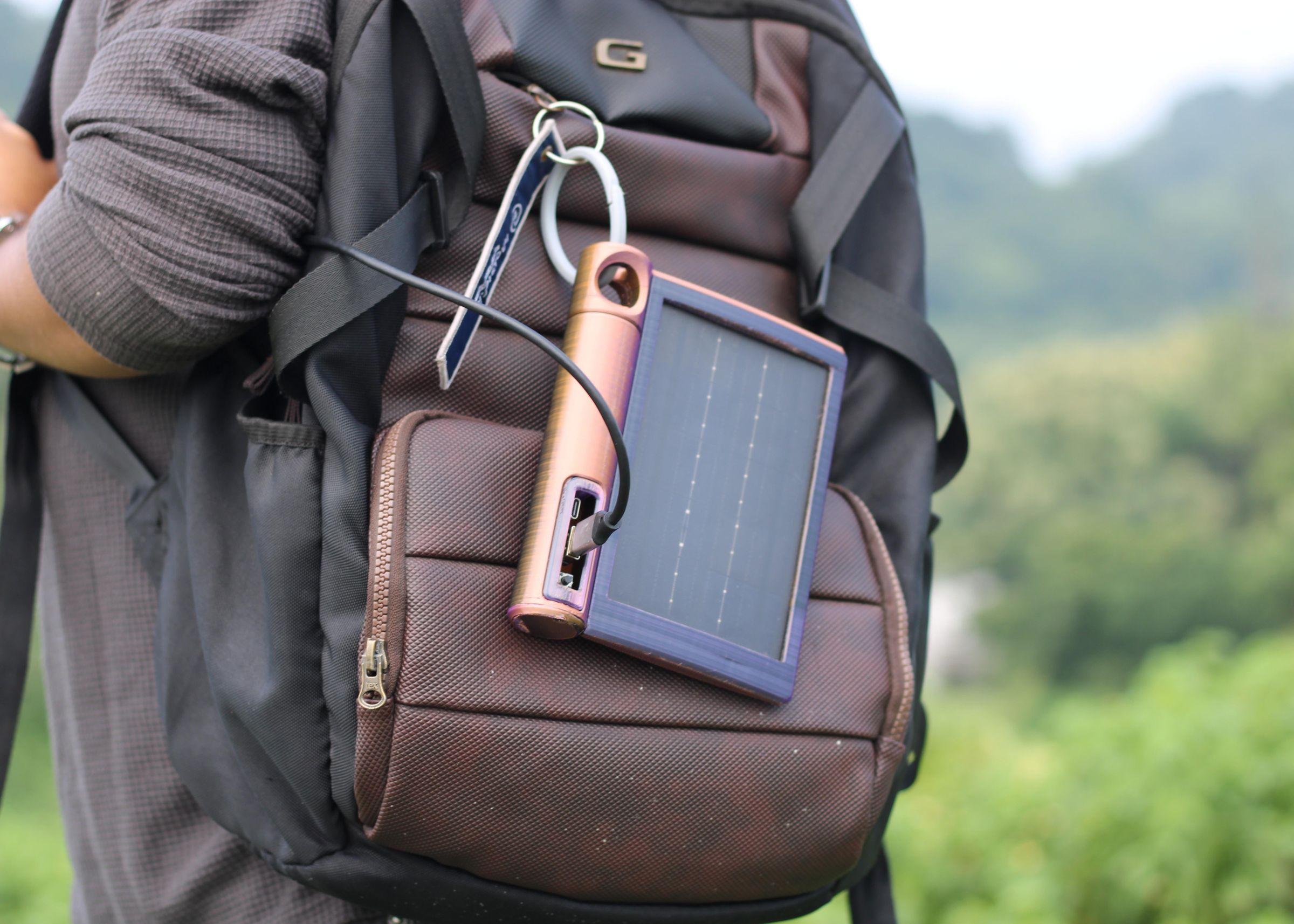
With its ultra-slim body and custom carabiner hook, SolMate can simply be clipped onto your backpack and left to charge as you explore. Whether you're hiking through the hills, traveling, or simply commuting around the city, SolMate uses nothing but sunlight to keep your devices powered.
While the original SolMate and this new version are electrically identical, SolMate 2.0 features several major design improvements. I redesigned the enclosure, improved the overall form factor, and made changes to make it more practical as an outdoor companion.
In this article, I'll walk you through the complete build process of SolMate 2.0, from the design and electronics to the final assembly.
So, let's get started!
Supplies
These were the materials used in this project:
- Custom PCB (provided by HQ NEXTPCB)
- IP5306
- 10 uF Capacitors SMD 1206 Package
- USB Port
- Type-C Port
- Inductor 1uH
- Solar Panel 2W PTFE
- 3D Printed Parts
- Li-ion Cell 3.7V 2000mAh
DESIGN
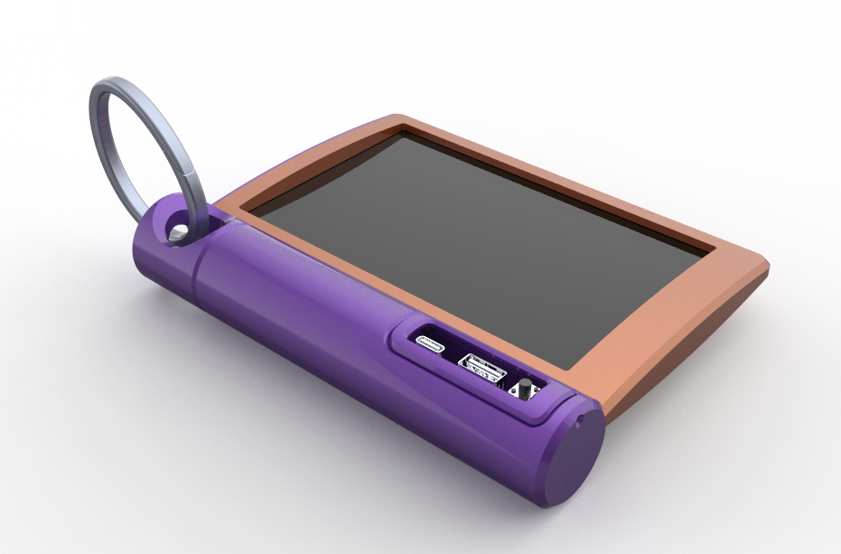
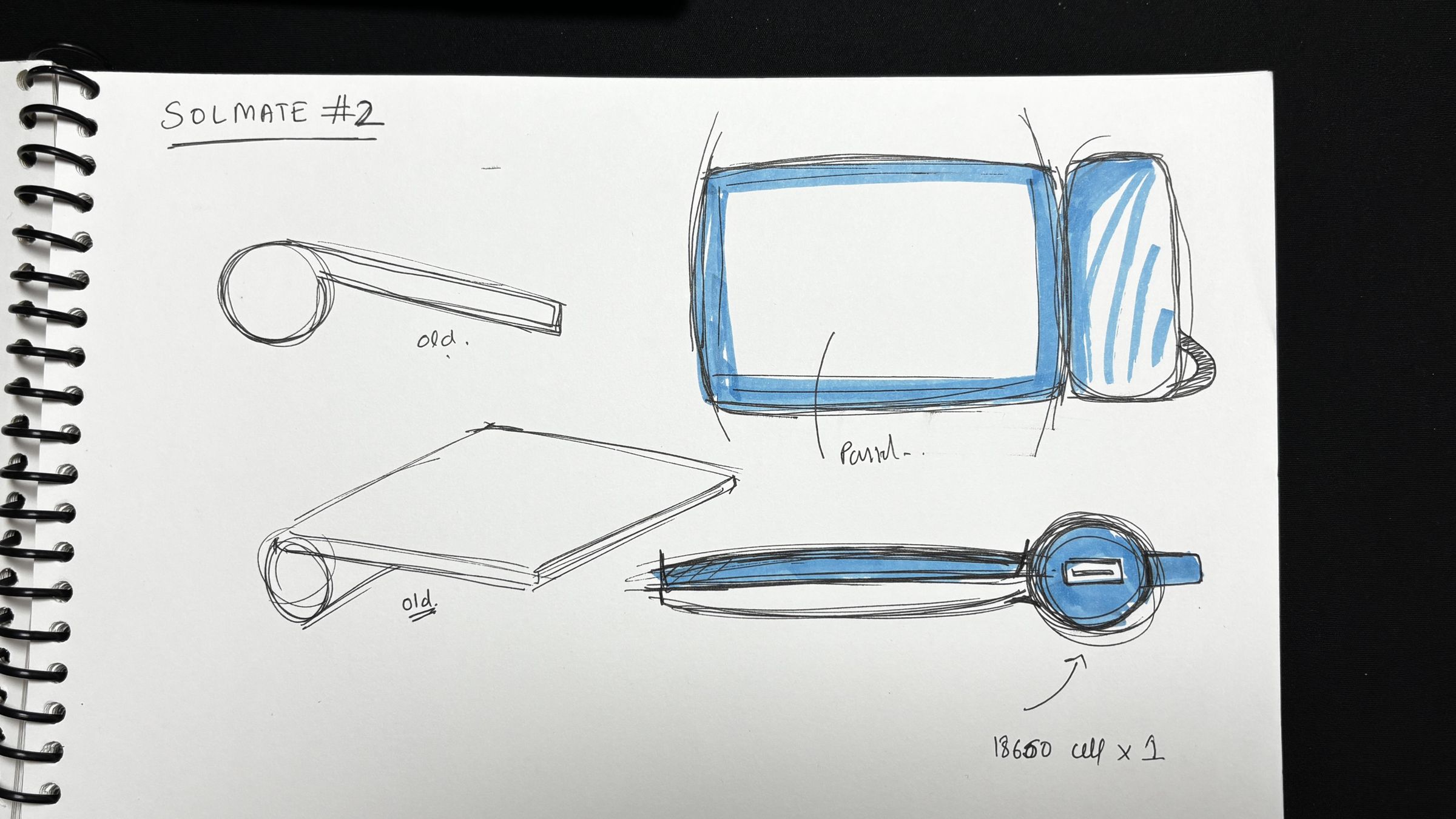
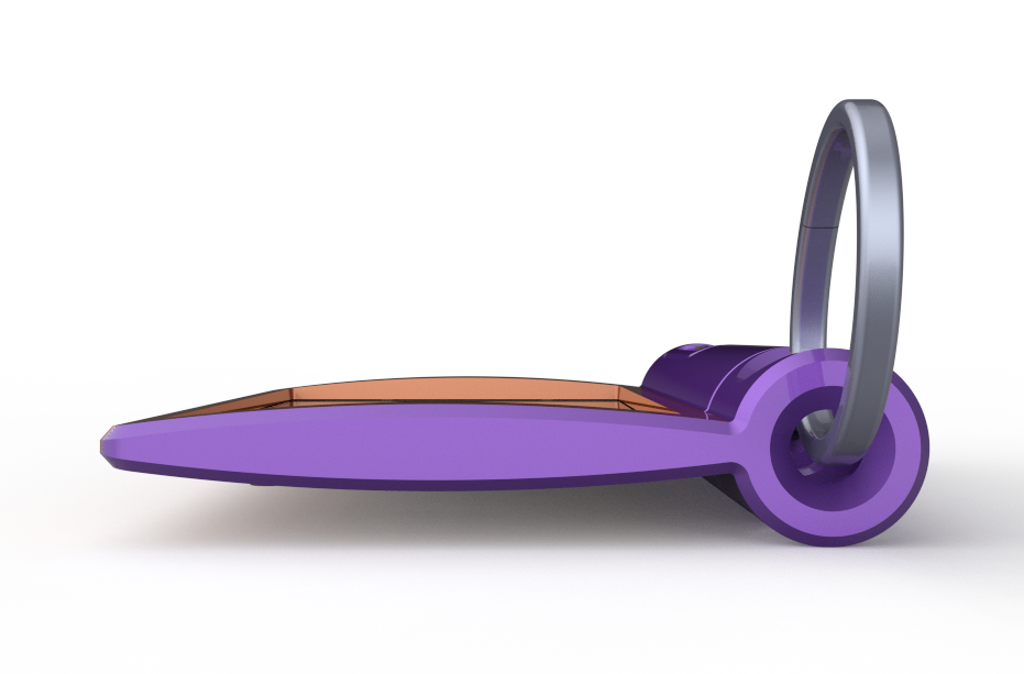
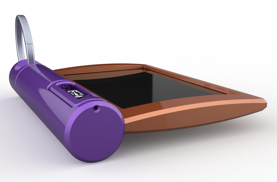
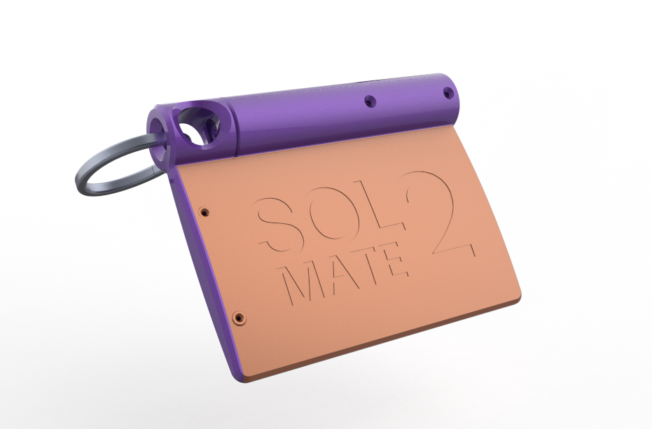
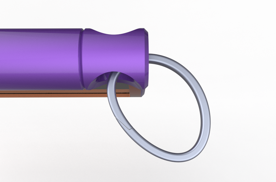
For the design of SolMate 2.0, I wanted to take a completely different approach rather than simply refining the original enclosure.
The first SolMate was inspired by the distinctive wedge-shaped profile of the Lenovo Yoga Tablet, with its cylindrical section housing the battery and electronics.
For version 2.0, I wanted to move away from that form language and create something that felt more like a purpose-built outdoor device.
I started with a curved, elongated enclosure for the solar panel, giving the main body a softer and more organic form. The electronics and battery are housed inside a cylindrical end section, creating a clear separation between the solar panel and the power-storage components while keeping the overall package slim.
The overall design follows a minimal, monolithic form language, with the curved solar-panel body transitioning into the cylindrical power section. The goal was to keep the enclosure compact and lightweight while making the mounting system an integral part of the product rather than an afterthought.
Compared to SolMate 1, this version is therefore not just a redesign of the enclosure; it introduces an entirely new form factor, visual language, and mounting concept while retaining the same basic electronics.
SOLAR & BATTERY HOLDER ASSEMBLY
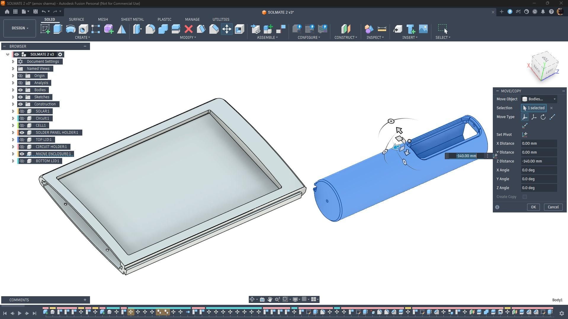
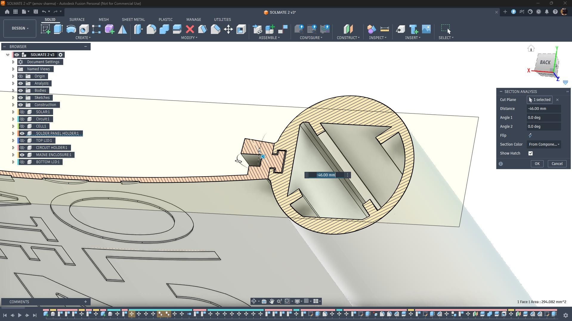
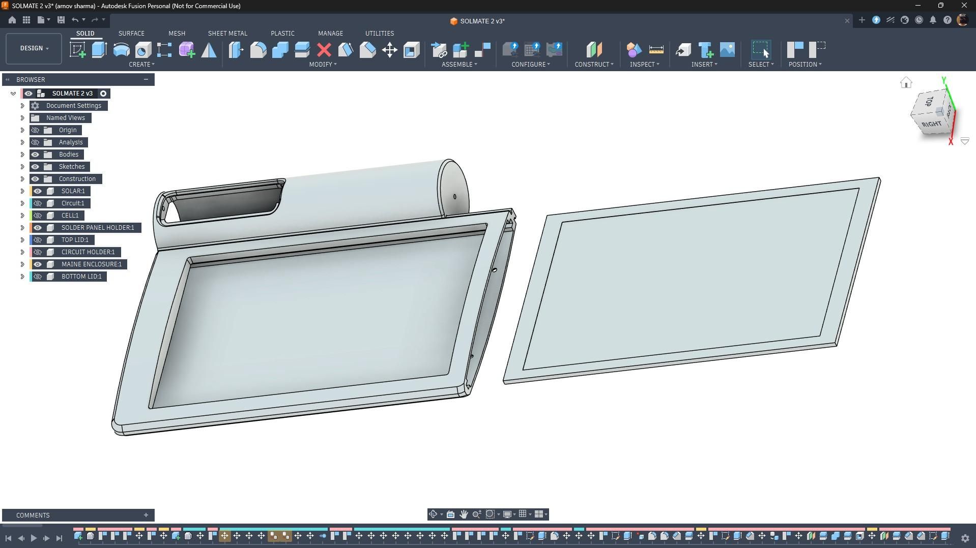
Construction of this project was super simple because the internals of SolMate 2.0 are similar to SolMate 1.0. All I had to do was redesign the body and make the assembly process much simpler.
This time, the enclosure wasn't designed as a single body. Instead, the solar panel holder and battery holder are separate parts, connected using a sliding mortise joint that I modeled between them.
The solar panel simply slides into its designated position, and a separate lid slides over it using another mortise joint integrated into the solar-panel holder. The lid is then secured in place with a single M2 screw, which is fastened to the battery-holder section.
This modular approach made the entire assembly much easier while also making the enclosure cleaner and more practical.
BATTERY & CIRCUIT HOLDER
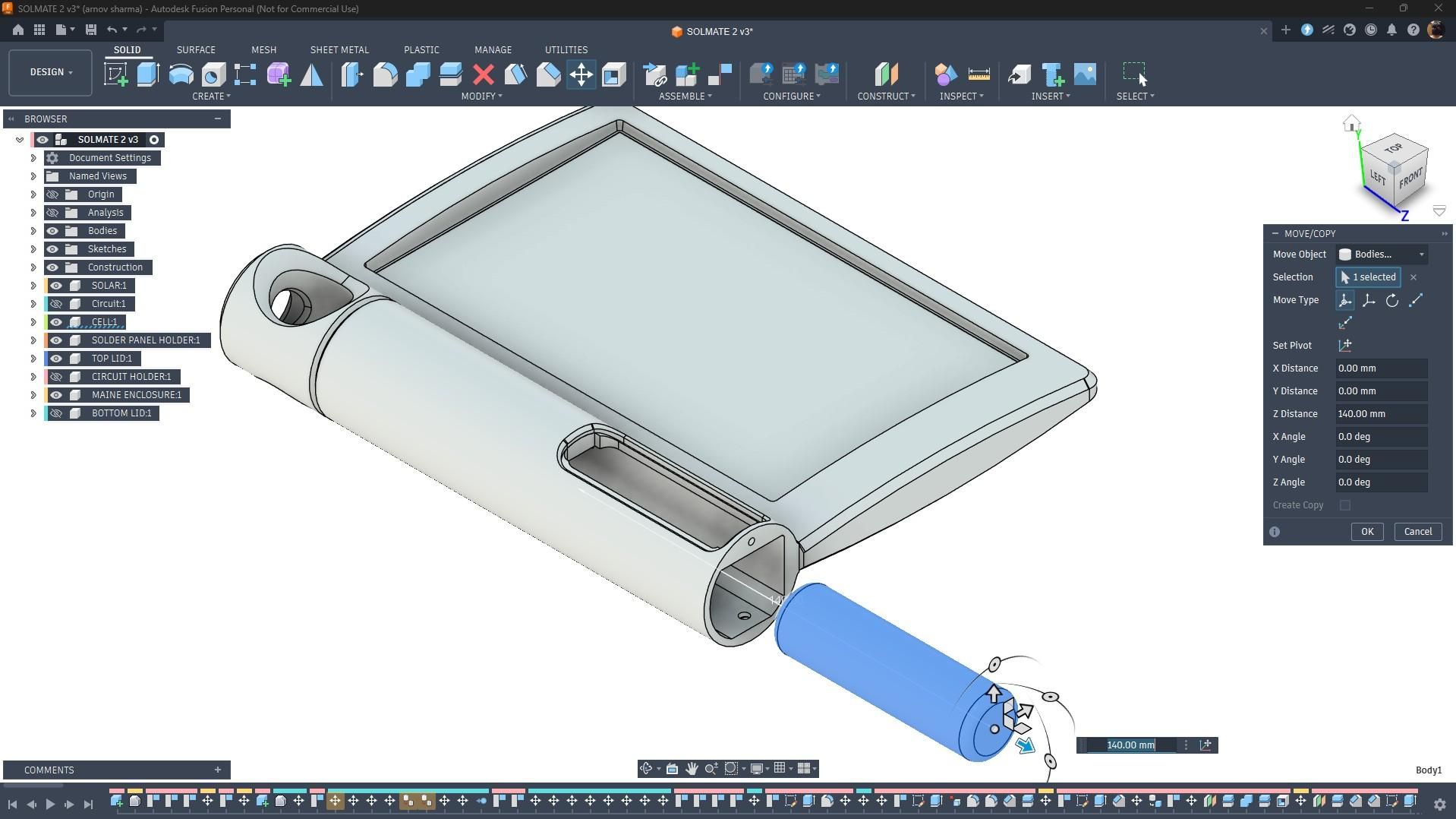
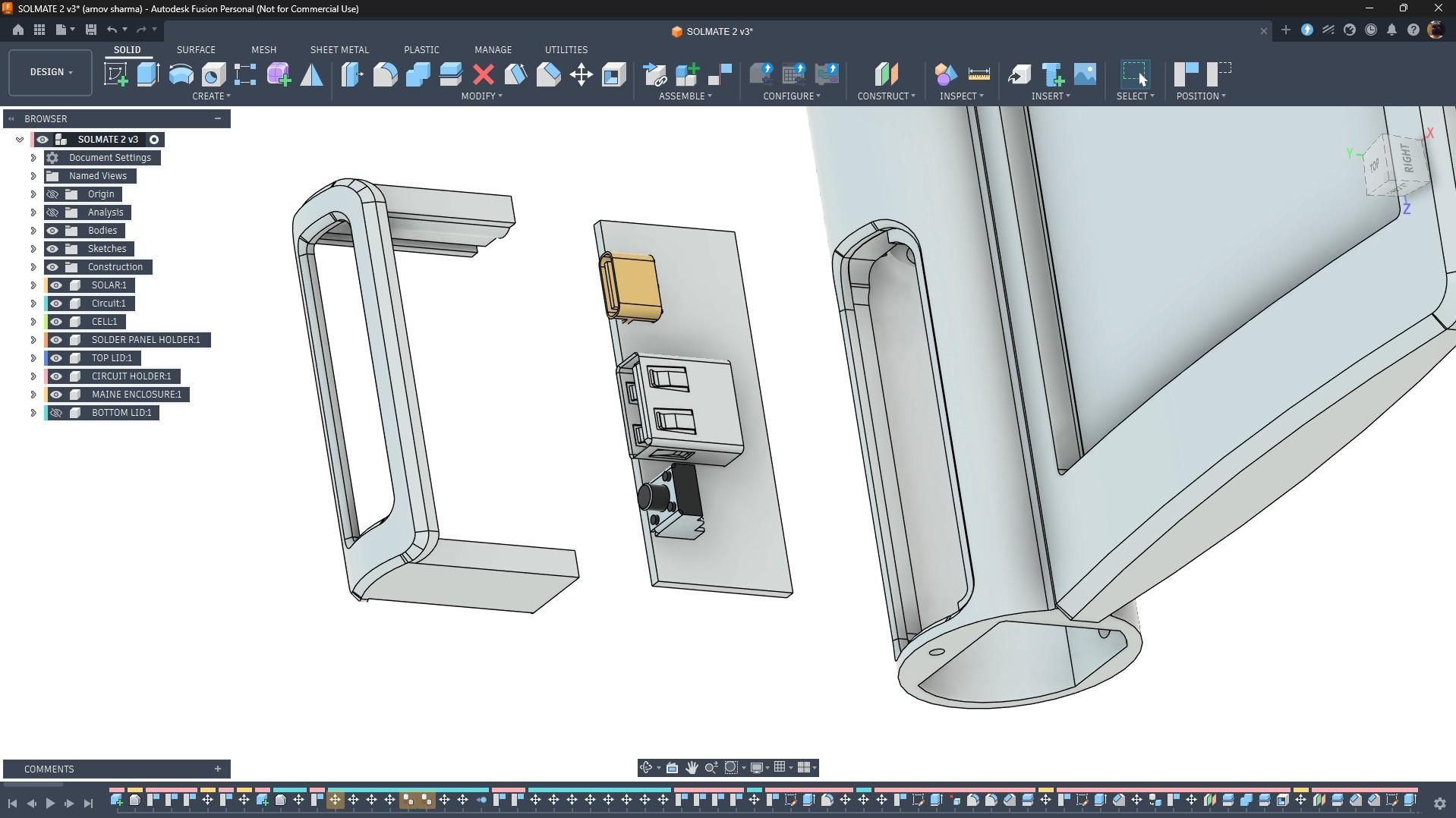
The Li-ion cell slides into its designated position inside the battery holder. I added a few retaining ribs inside the holder to keep the cell securely in place and prevent it from moving around.
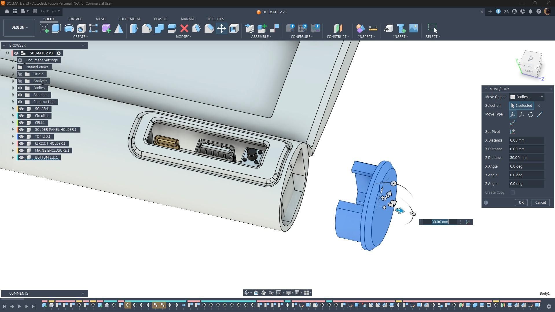
Next, we have the circuit holder, which the circuit board slides into. Once the circuit is fitted into the holder, the entire assembly slides into the slot provided on the battery holder from the rear side. The circuit holder is then secured to the battery holder using two M2 screws.
Finally, the rear opening of the battery holder is covered with a lid, which is secured in place using a single M2 screw.
3D PRINTED PARTS
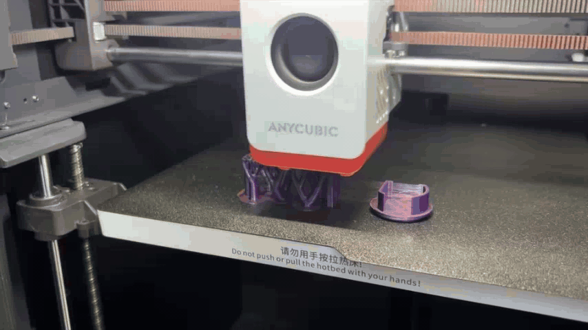
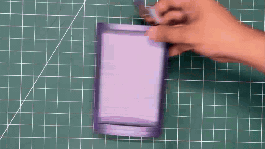
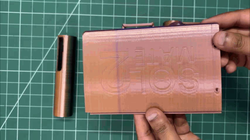
For the 3D printing, all parts, including the solar holder and battery holder, were printed using tri-color PLA, which gives the parts a purple, yellow, and brownish appearance. This color combination complements the red enclosure quite well.
I printed the solar holder and battery holder in a vertical orientation to reduce support marks and achieve a smoother surface finish.
PCB DESIGN
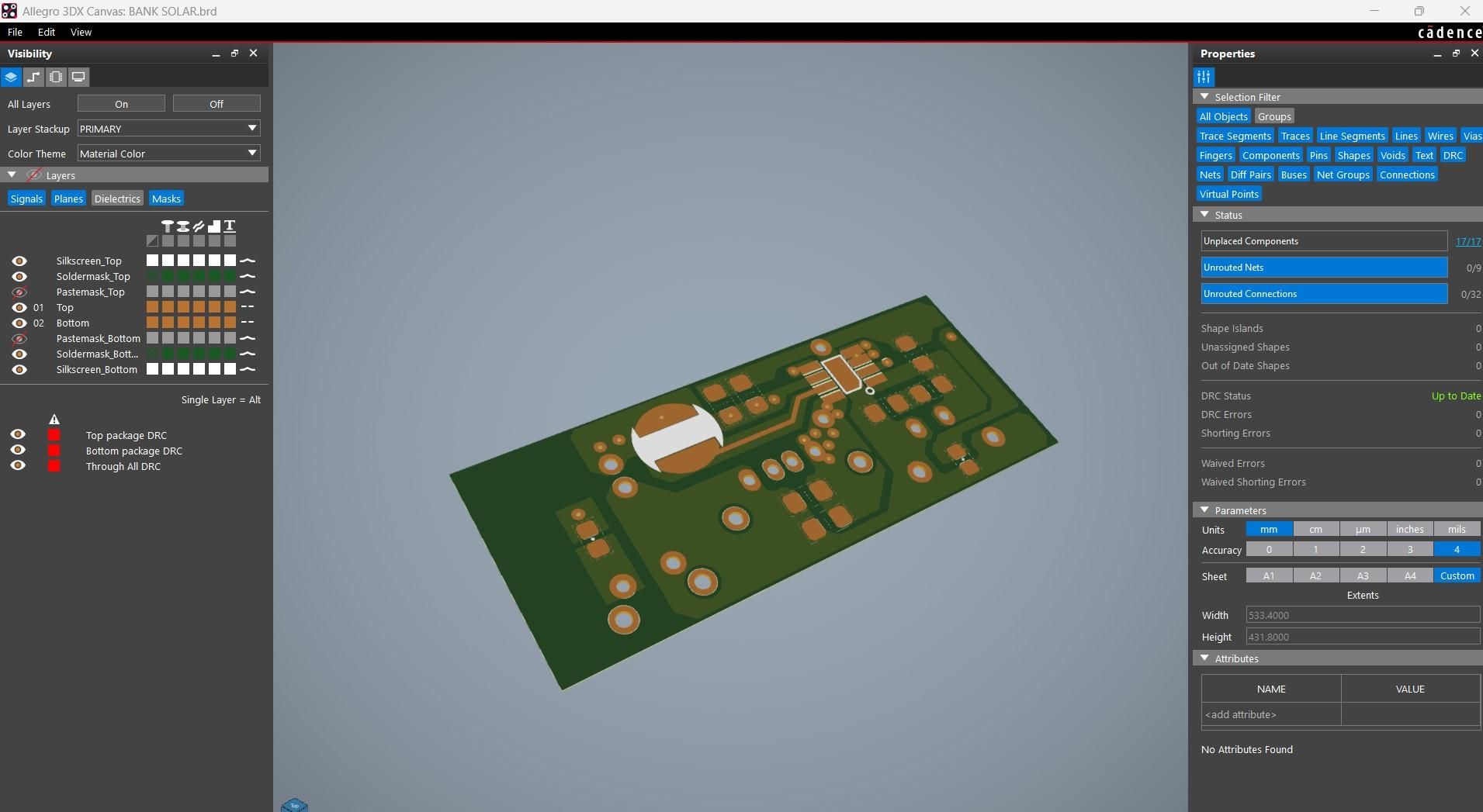
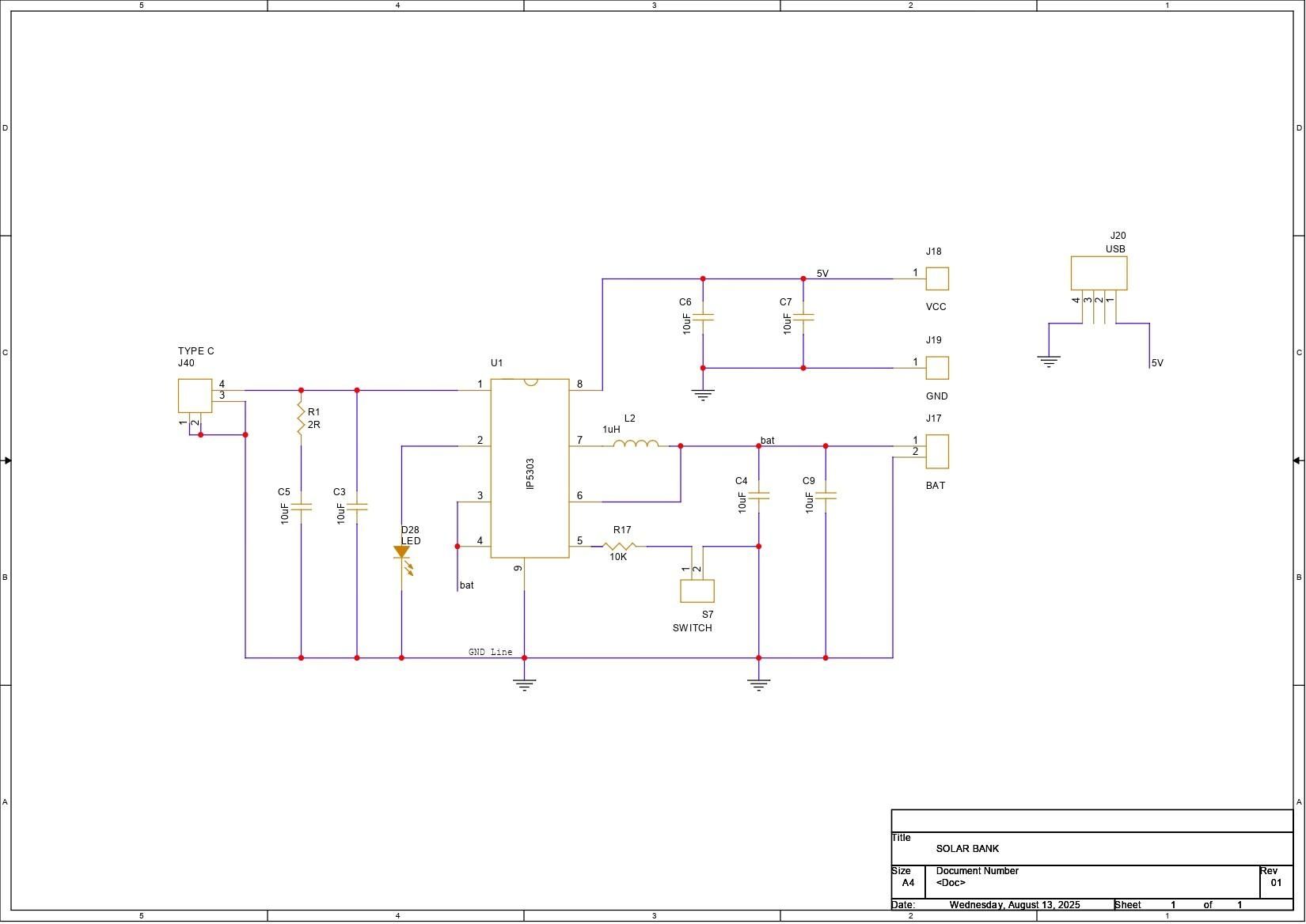
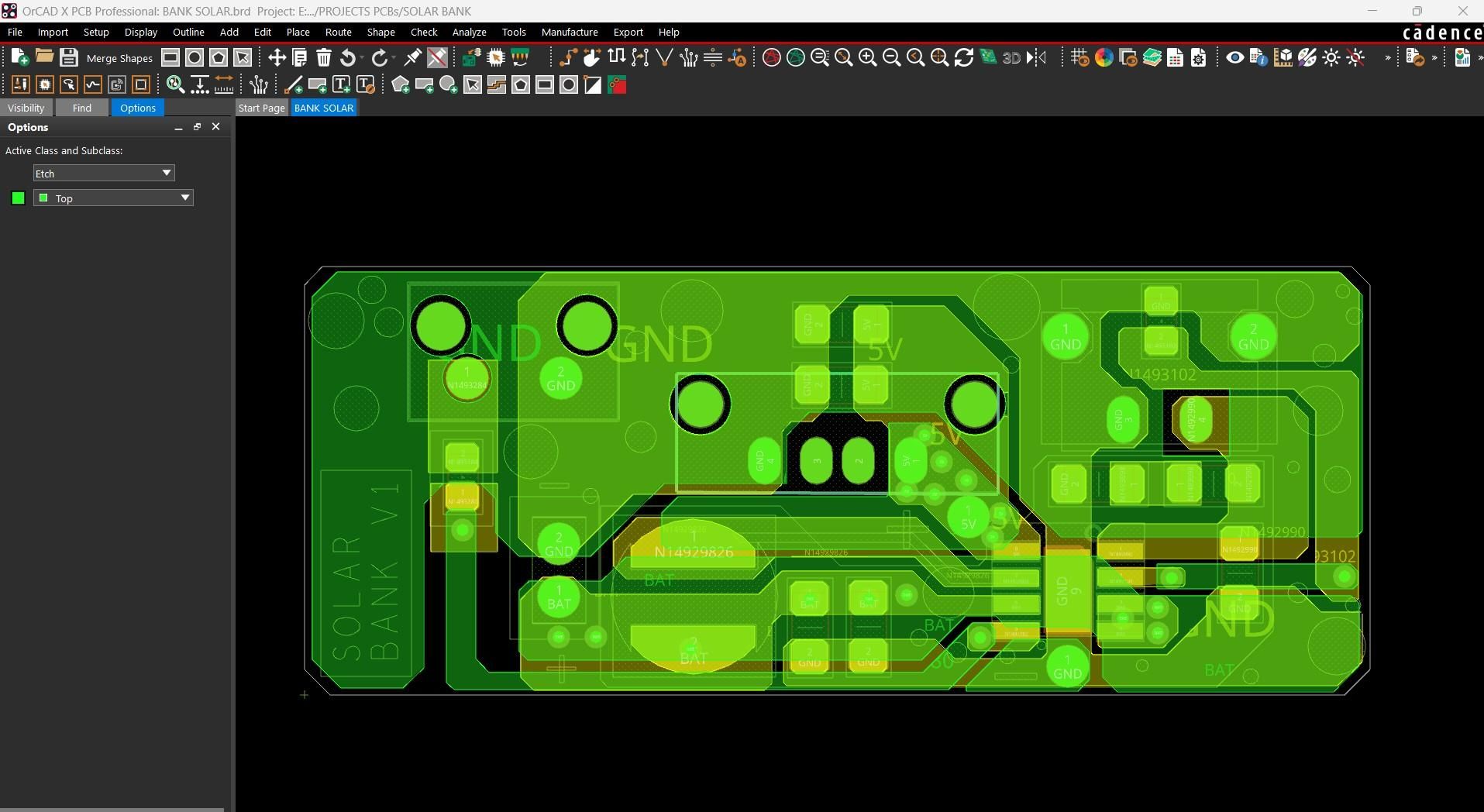
Here we are using the IP5306 Power Management IC Setup, which we have previously used in many of our battery-related projects. This SOIC8 package IC can provide a stable 5V 2.4A from a 3.7V lithium-ion or LIPO cell and also includes many important functions such as overcharging protection, overdischarge, battery fuel level, and charging status.
Below is its datasheet if you want more info on this IC.
https://www.skytech.ir/DownLoad/File/2566_IP5306.pdf
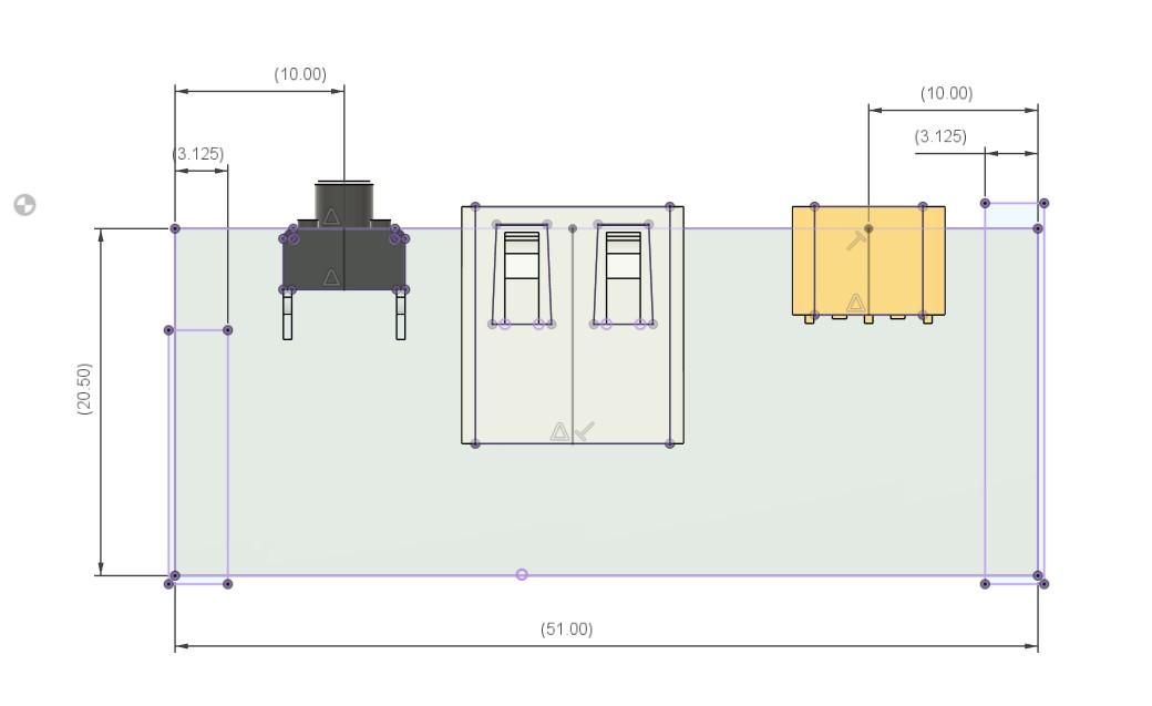
We created the board outline in PCB CAD by following the customized circuit design from our Fusion 360 CAD file. We finalized the board layout by placing all the components in order with the CAD's measurements. Once everything lined up, we prepared the final board for fabrication.
NextPCB PCB Service
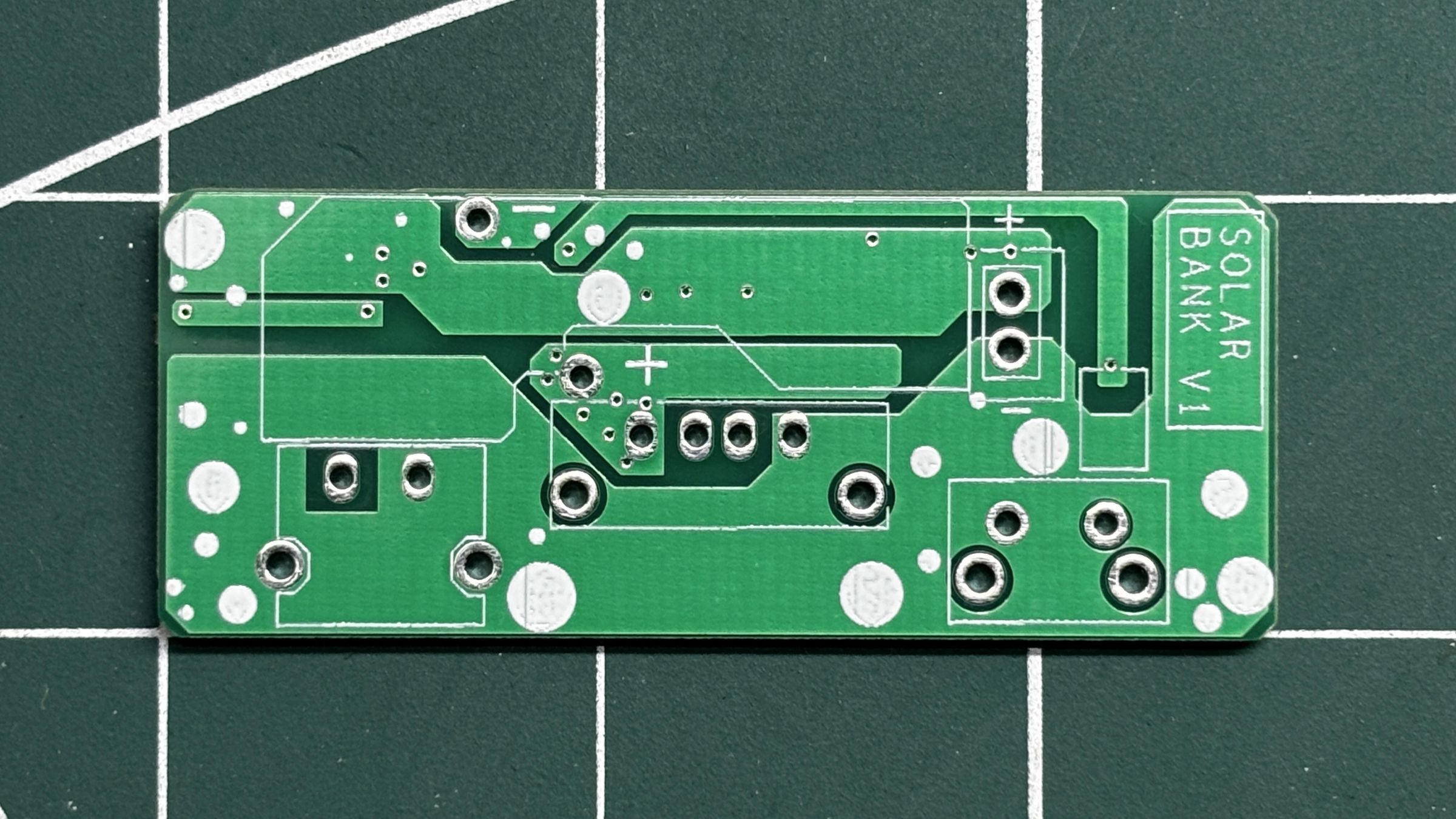
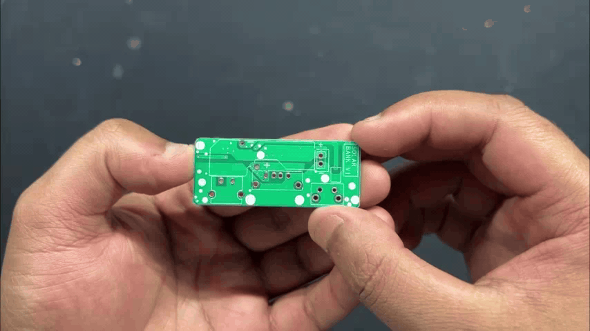
After completing the PCB design, Gerber data was sent to HQ NextPCB, and an order was placed for a white solder mask with black silkscreen.
After placing the order, the PCBs were received within a week, and the PCB quality was pretty great.
In addition, I have to bring in HQDFM to you, which helped me a lot through many projects. Huaqiu’s in-house engineers developed the free Design for Manufacturing software, HQDFM, revolutionizing how PCB designers visualize and verify their designs.
Take advantage of NextPCB's Accelerator campaign and get 2 free assembled RP2040-based PCBs for your innovative projects.
https://www.nextpcb.com/blog/rp2040-free-pcba-prototypes-nextpcb-accelerator
This offer covers all costs, including logistics, making it easier and more affordable to bring your ideas to life. SMT services can be expensive, but NextPCB is here to help you overcome that hurdle. Simply share your relevant project, and they'll take care of the rest. Don't miss out on this amazing opportunity to advance your tech creations!
HQDFM: Free Online Gerber Viewer and DFM Analysis Tool
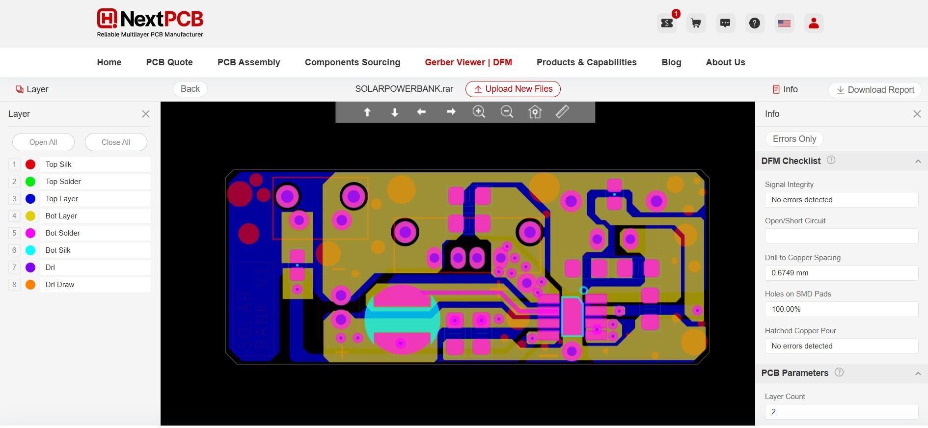
Also, NextPCB has its own Gerber Viewer and DFM analysis software.
Your designs are improved by their HQDFM software (DFM) services. Since I find it annoying to have to wait around for DFM reports from manufacturers, HQDFM is the most efficient method for performing a pre-event self-check.
This is what I see in the online Gerber Viewer. It's decent for a quick look, but not entirely clear. For full functionality—like detailed DFM analysis for PCBA—you’ll need to download the desktop software. The web version only offers a basic DFM report.
With comprehensive Design for Manufacture (DFM) analysis features, HQDFM is a free, sophisticated online PCB Gerber file viewer.
With over 15 years of industry experience, it offers valuable insights into advanced manufacturing processes. If you’re looking for reliable PCB services at a budget-friendly price, HQ NextPCB is definitely worth checking out.
PCB ASSEMBLY PROCESS
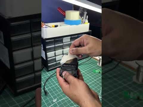
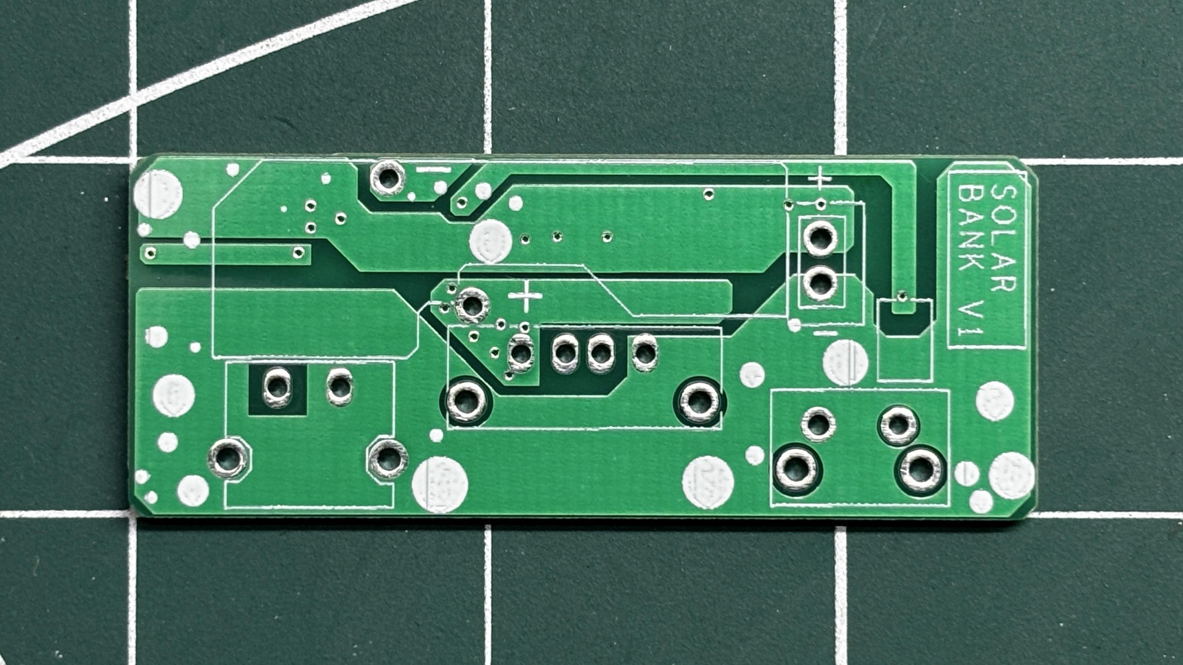
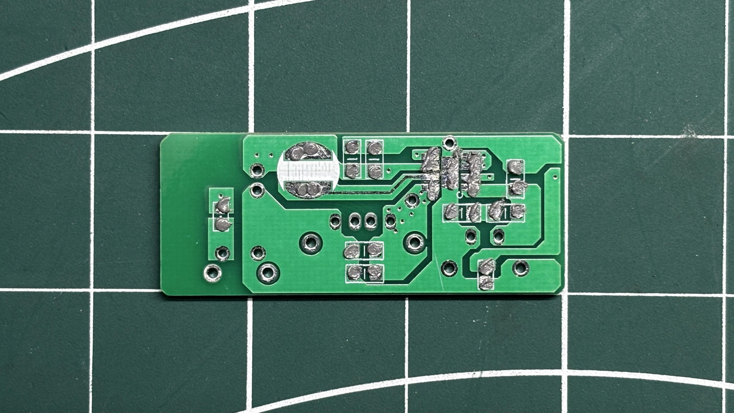
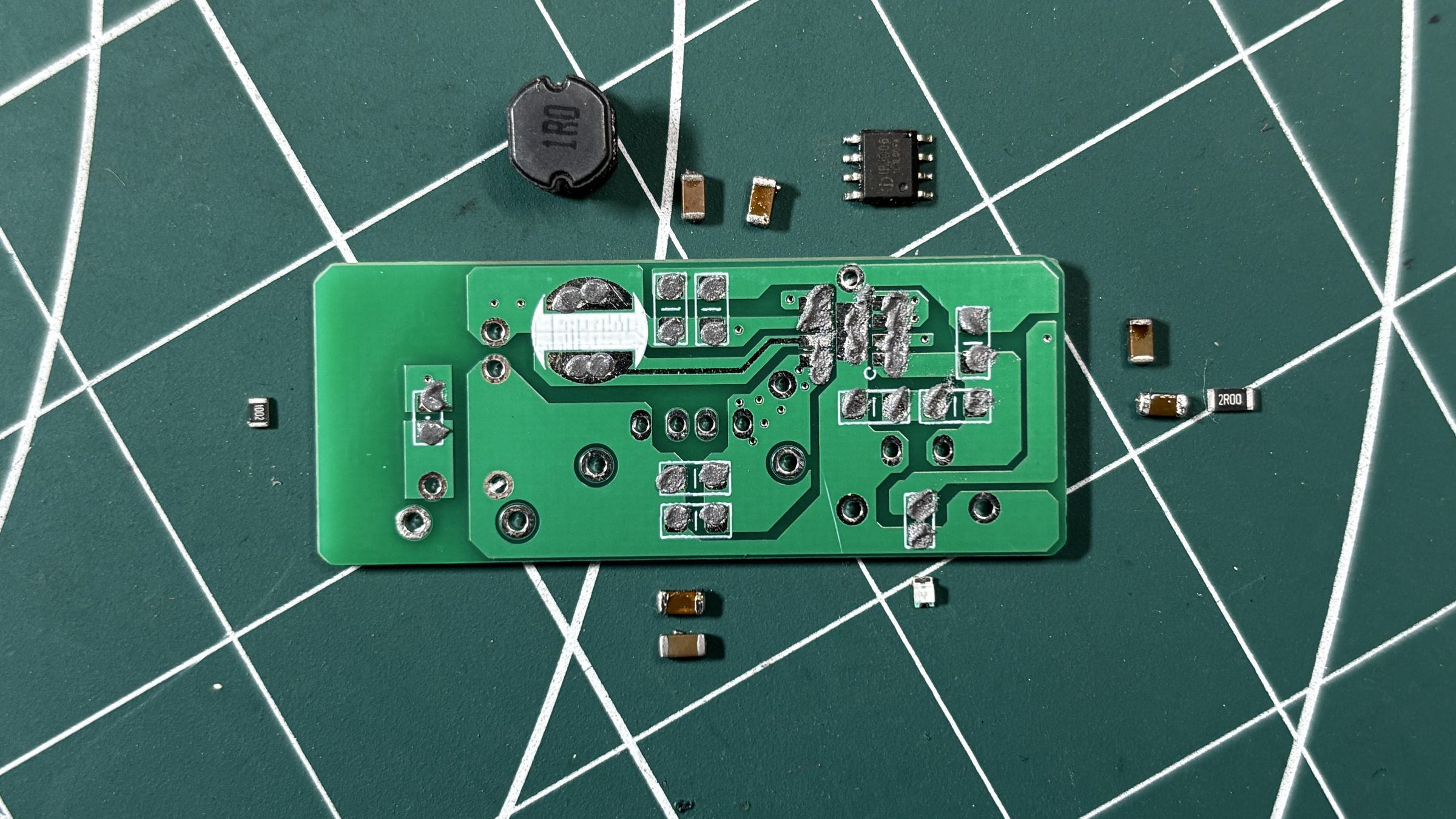
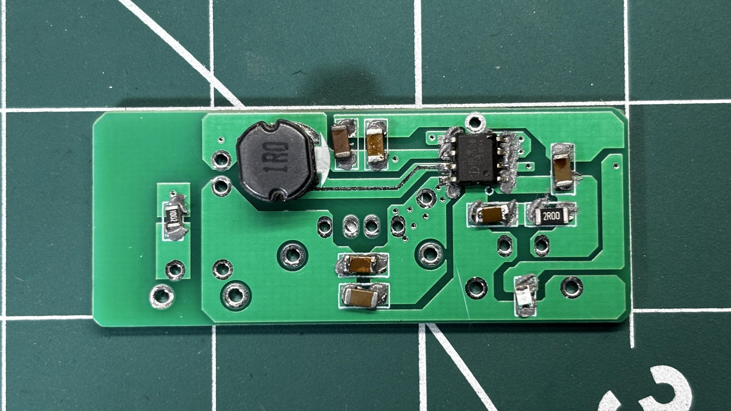
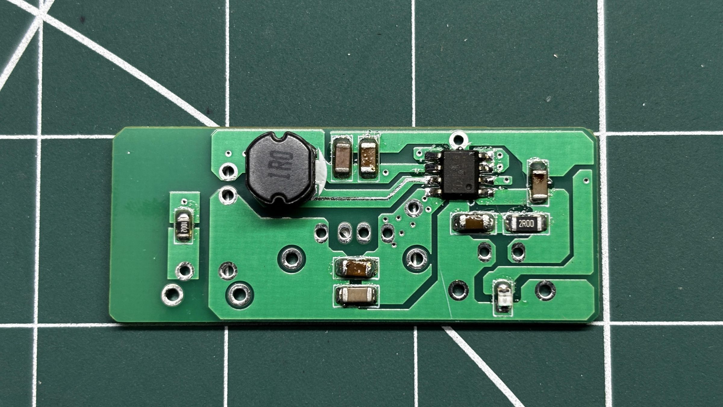
- PCB assembly starts by applying solder paste to each SMD pad using a dispensing syringe. We’re using standard 63/37 Sn-Pb solder paste.
- Once that’s done, each SMD component is placed in position using ESD-safe tweezers.
- The board then goes onto a mini reflow hotplate, which heats it from below. As soon as the temperature hits around 200°C, the solder paste melts, and the components are soldered in place.
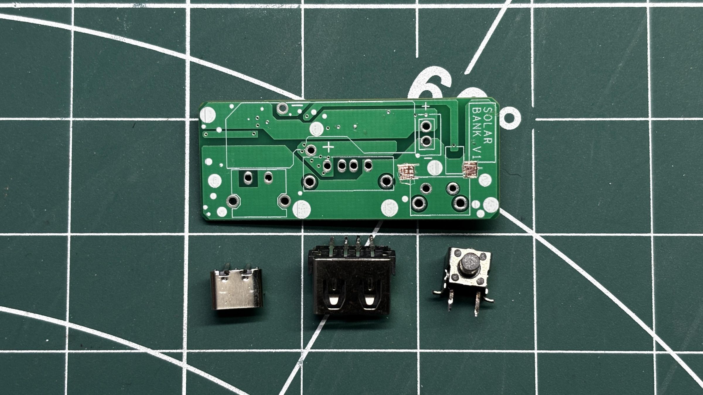
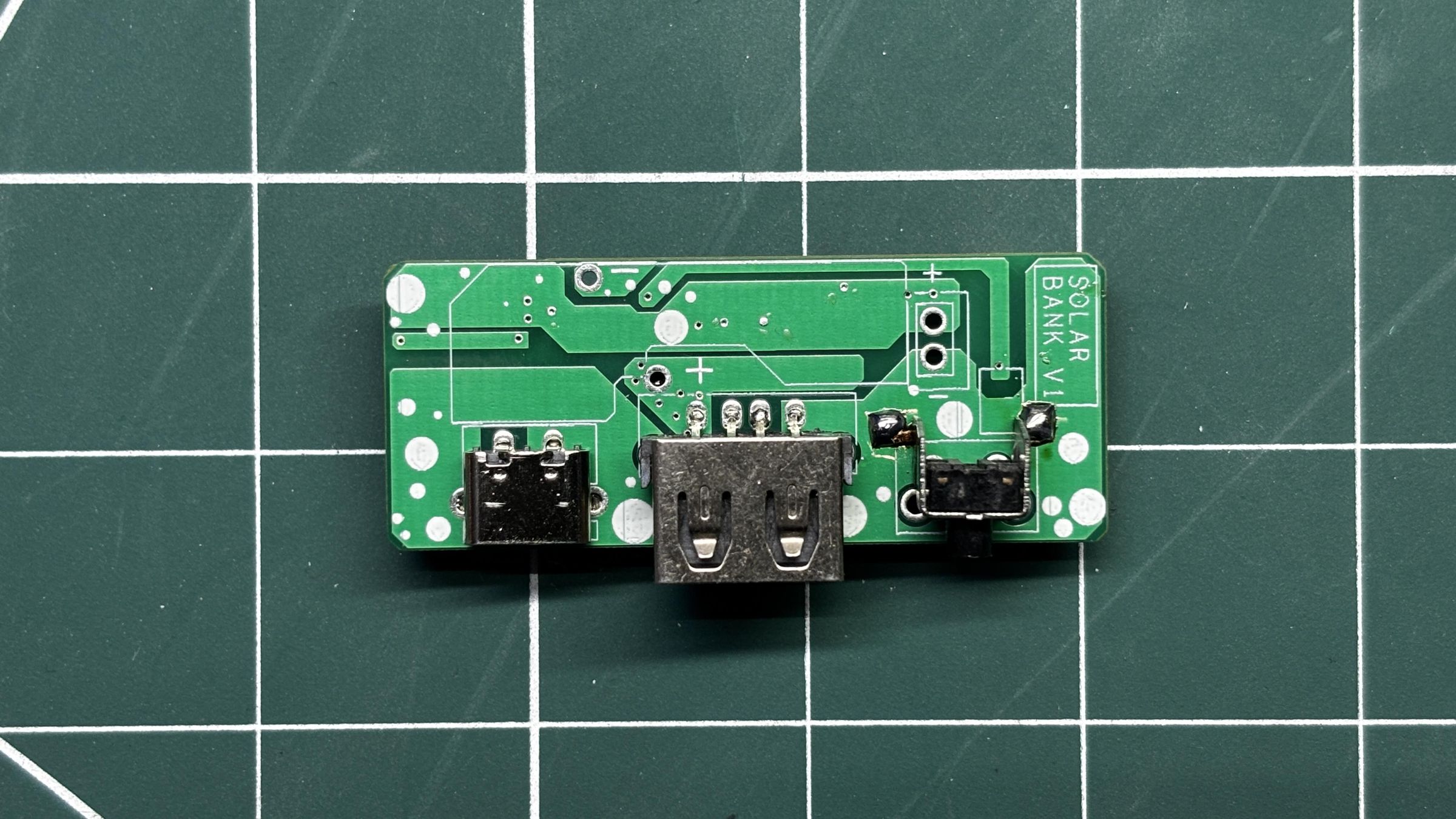
- Next, we move on to the through-hole components, which begins by placing the push button, Type C Port, and USB port in their position.
- After placing them, we flip the PCB and solder the through-hole pads using a soldering iron. That wraps up the full assembly process.
POWER SOURCE
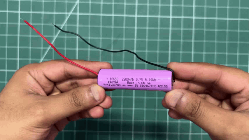
For power, we’re using a 3.7V 2200mAh Li-ion cell, which works well for this setup. Since the panel is rated at 2W, going with a larger battery would just slow down charging.
2W PTFE SOLAR PANEL
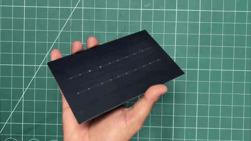
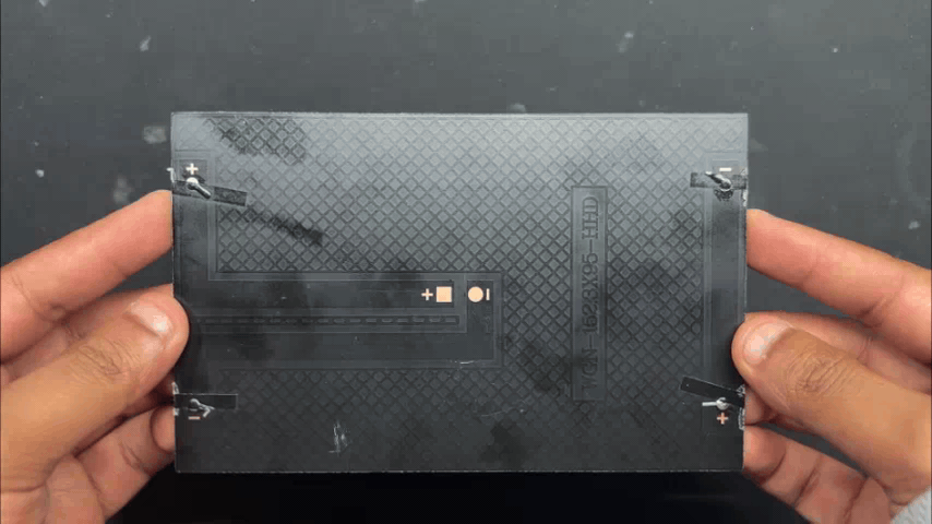
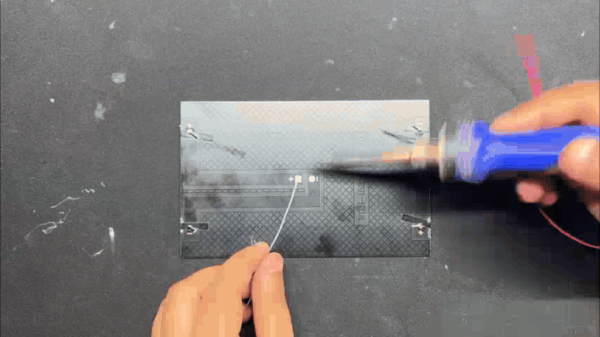
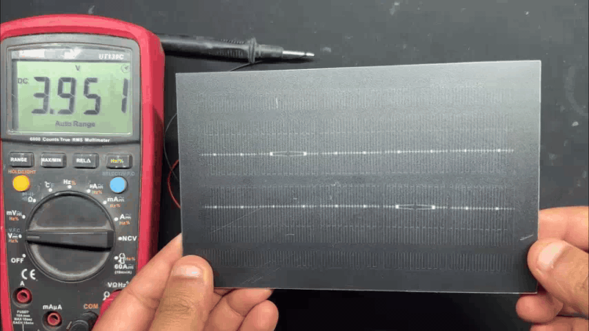
For SolMate 2.0, I'm reusing the 2W PTFE solar panel from the previous SolMate project.
Polytetrafluoroethylene, or PTFE, is the same material commonly associated with Teflon and non-stick cookware, so this is definitely not your typical solar panel.
Instead of using conventional glass as the protective layer, PTFE can be used as a flexible, lightweight, and weather-resistant surface for solar panels. This makes the panel considerably lighter and thinner than traditional glass-covered panels, while also making it much more resistant to cracking or breaking.
However, there is a trade-off. PTFE can scatter incoming sunlight more than a conventional glass surface. This means that slightly less direct light reaches the solar cells underneath, which can result in somewhat lower efficiency compared with high-transmission glass panels that use anti-reflective coatings. The benefit is that we get a much lighter and more rugged panel, which is ideal for a portable outdoor project like SolMate.
For testing, I connected two wires to the panel's positive and negative terminals and measured its output using a multimeter. Under indoor lighting, the panel produced around 3.9V. Since this test was performed inside a room rather than under direct sunlight, the output is significantly lower than what we can expect outdoors.
The panel is rated at around 5V nominal output and can reach higher voltages under suitable lighting conditions, making it suitable as the solar input for the power-management circuit used in SolMate 2.0. The power-management circuit then handles the solar input and safely manages the charging of the Li-ion battery.
BATTERY HOLDER & CIRCUIT ASSEMBLY
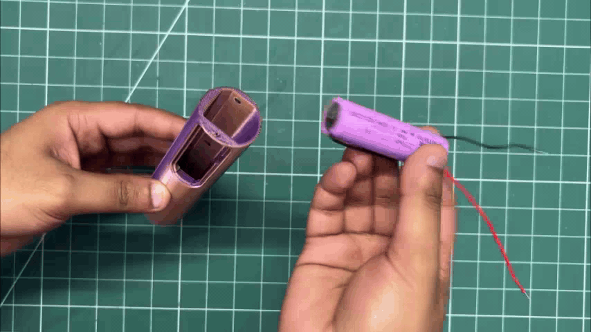
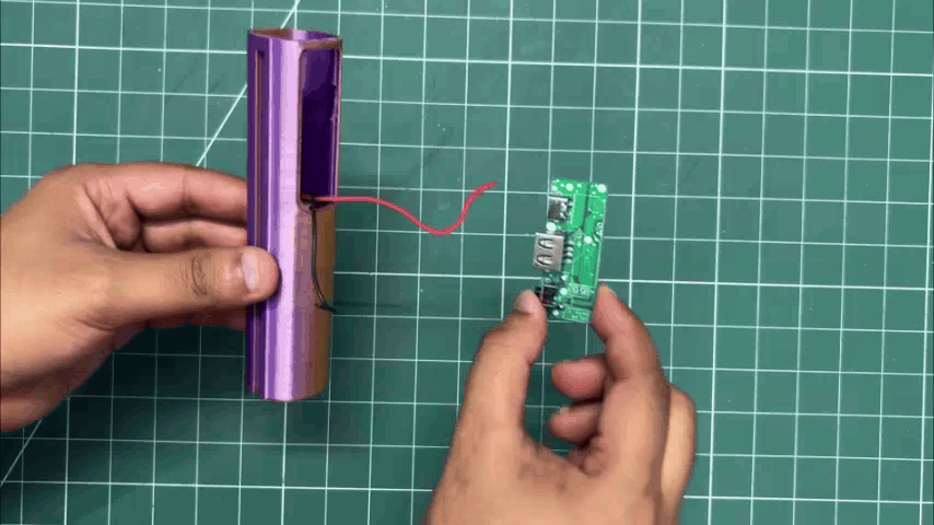
- Assembly begins with placing the Li-ion cell inside the battery holder.
- We pass the battery wires through the window provided on the battery holder and then connect the battery terminals to the B+ and B− terminals of the power circuit.
SOLAR PANEL & BODY ASSEMBLY
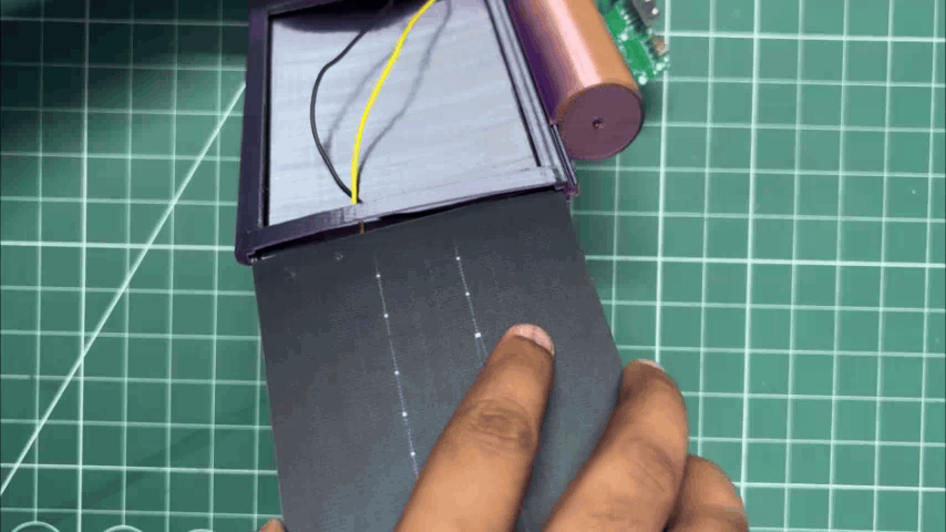
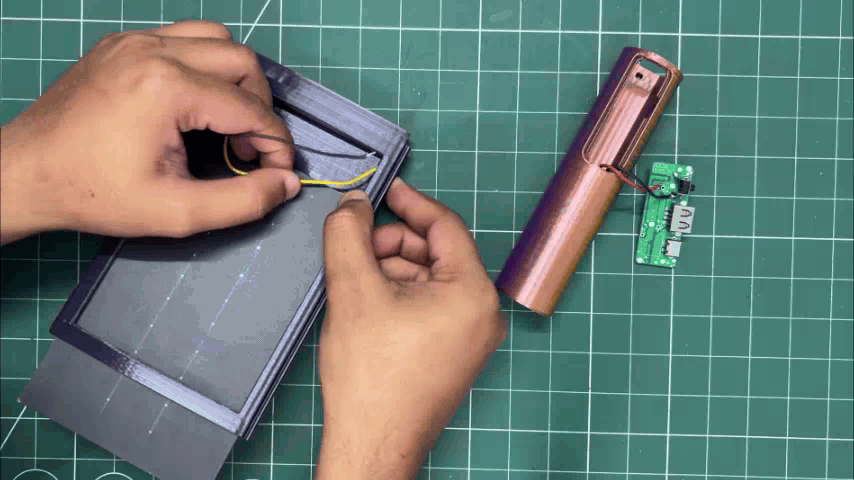
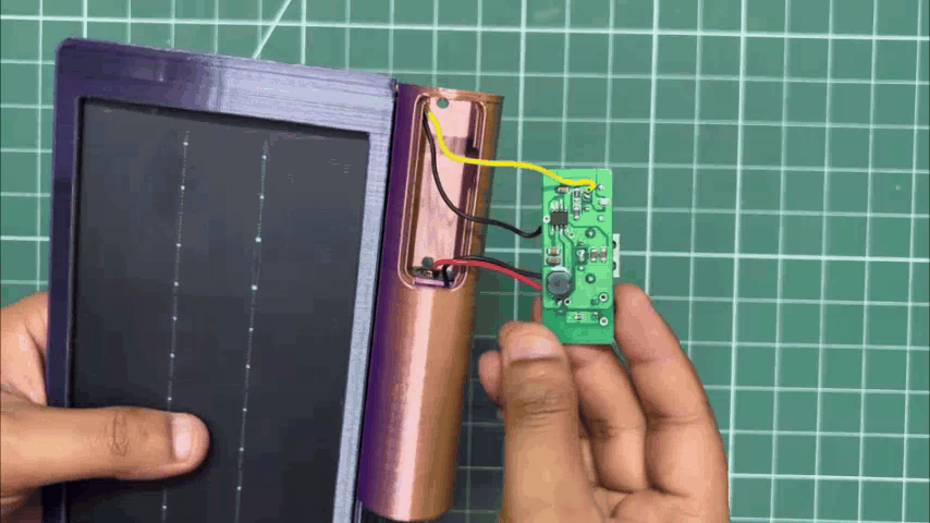
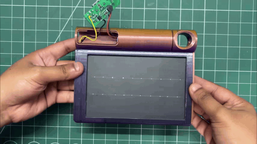
- The battery holder is slid into the solar holder using the mortise joint rails provided on both parts.
- Next, we place the PTFE solar panel into position by sliding it inside the solar holder.
- The solar panel wires are then passed through the opening provided on the solar holder.
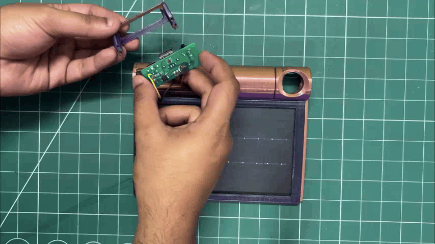
- The wires are routed inside the battery holder toward the power circuit, where they are soldered in parallel with the VCC and GND pins of the USB port.
BODY ASSEMBLY
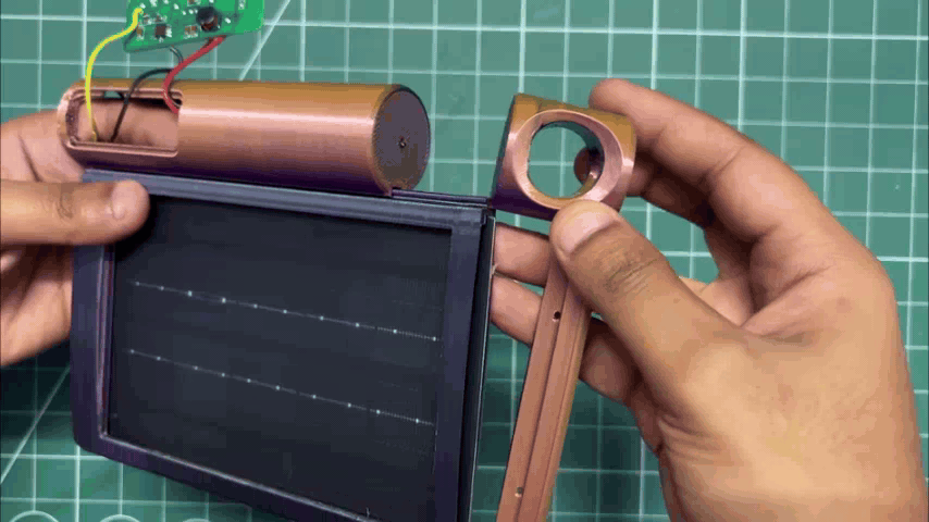
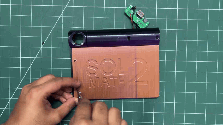
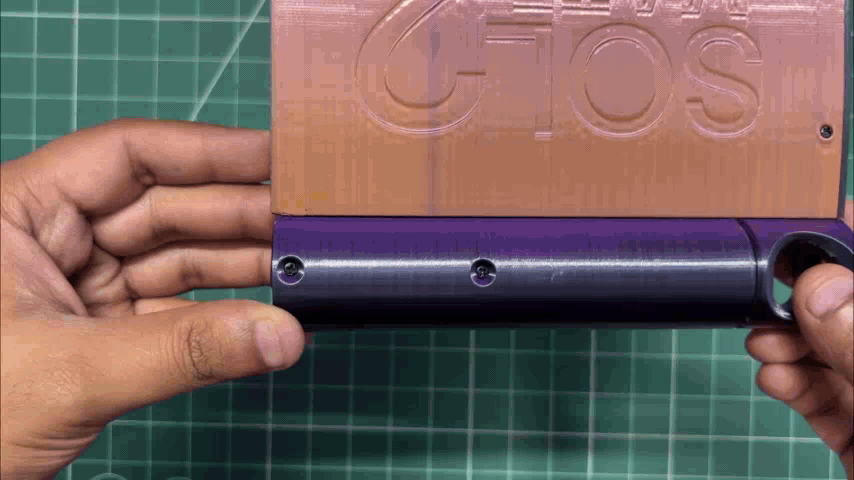
- To keep the solar holder and battery holder securely locked in position, we slide the special top lid into the mortise rail on the solar holder.
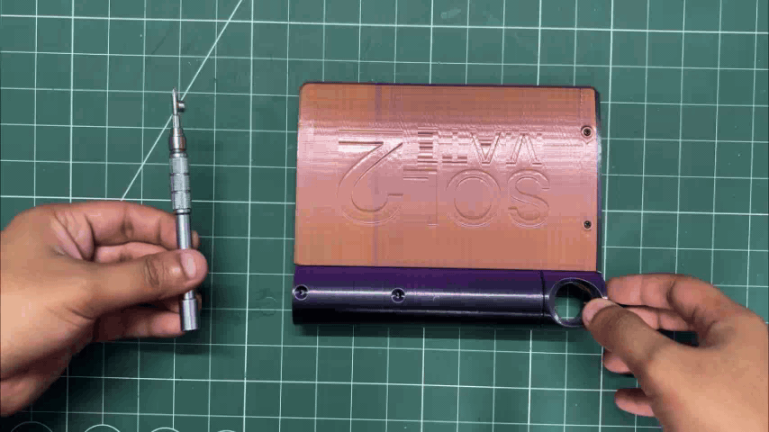
- We then use a single M2 screw to secure the lid to the battery holder.
- Next, we turn the device over and use two additional M2 screws to secure the lid to the solar holder.
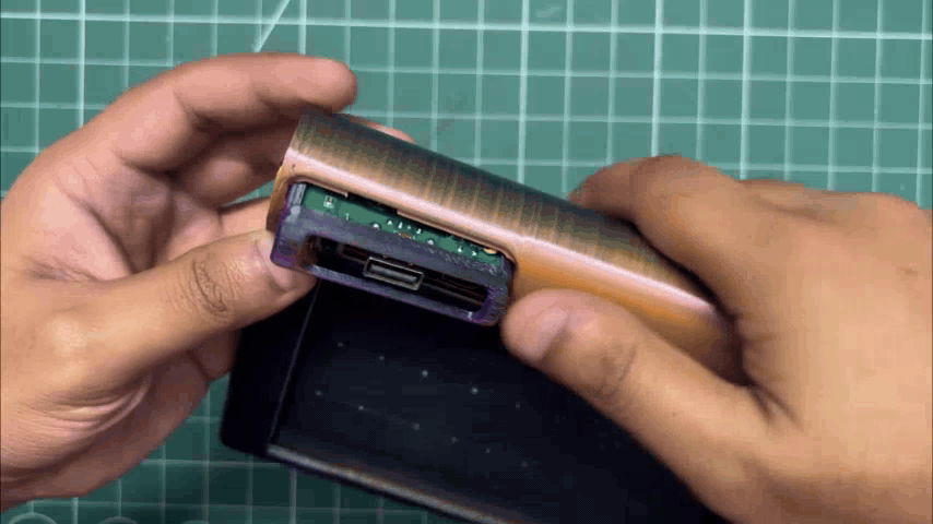
- The circuit is then slid into the circuit holder, and the entire circuit-holder assembly is fitted into the window opening of the battery holder from the rear side.
- Finally, we use two M2 screws to secure the circuit holder firmly in place.
FINAL ASSEMBLY
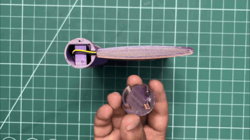
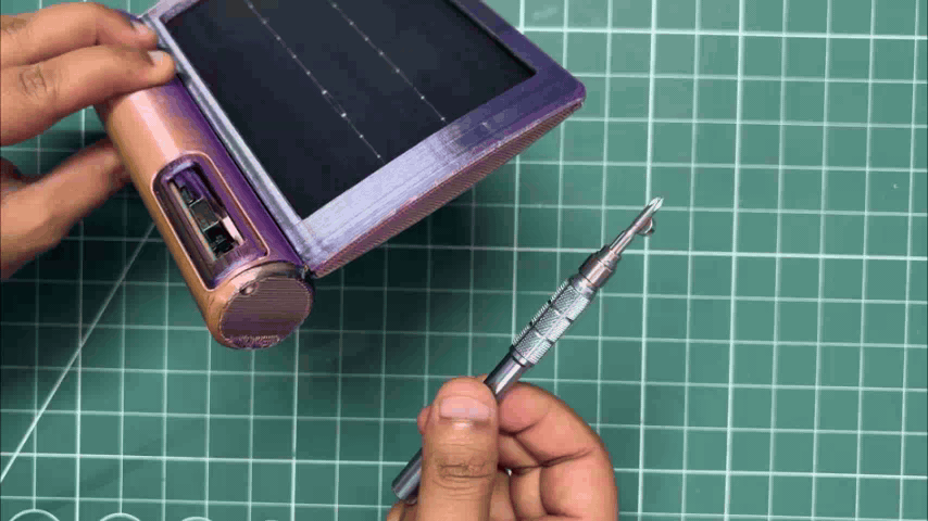
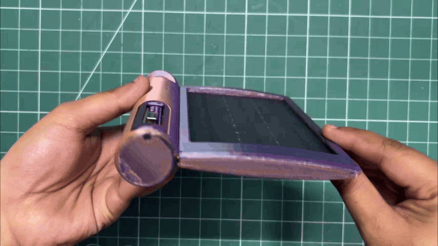
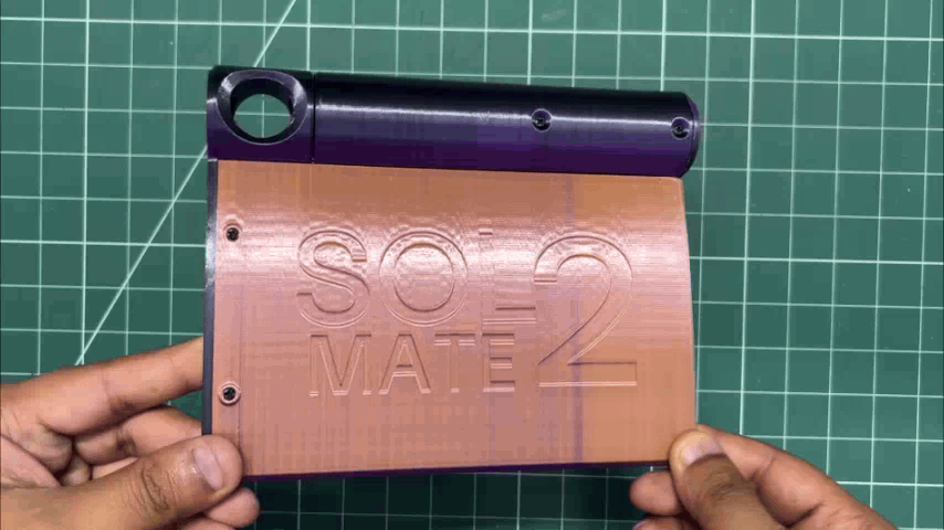
For the final assembly, we just need to add the bottom lid to the battery holder and use a single M2 screw to secure it in place.
With that, the project is finally complete.
RESULT
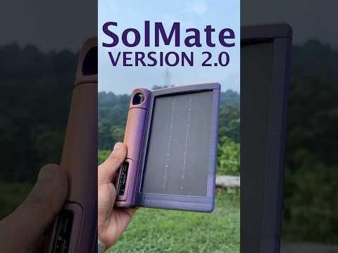
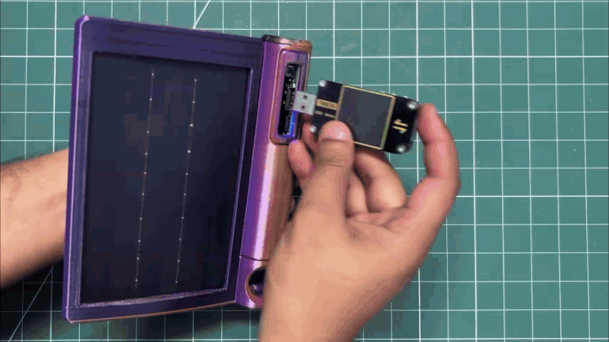
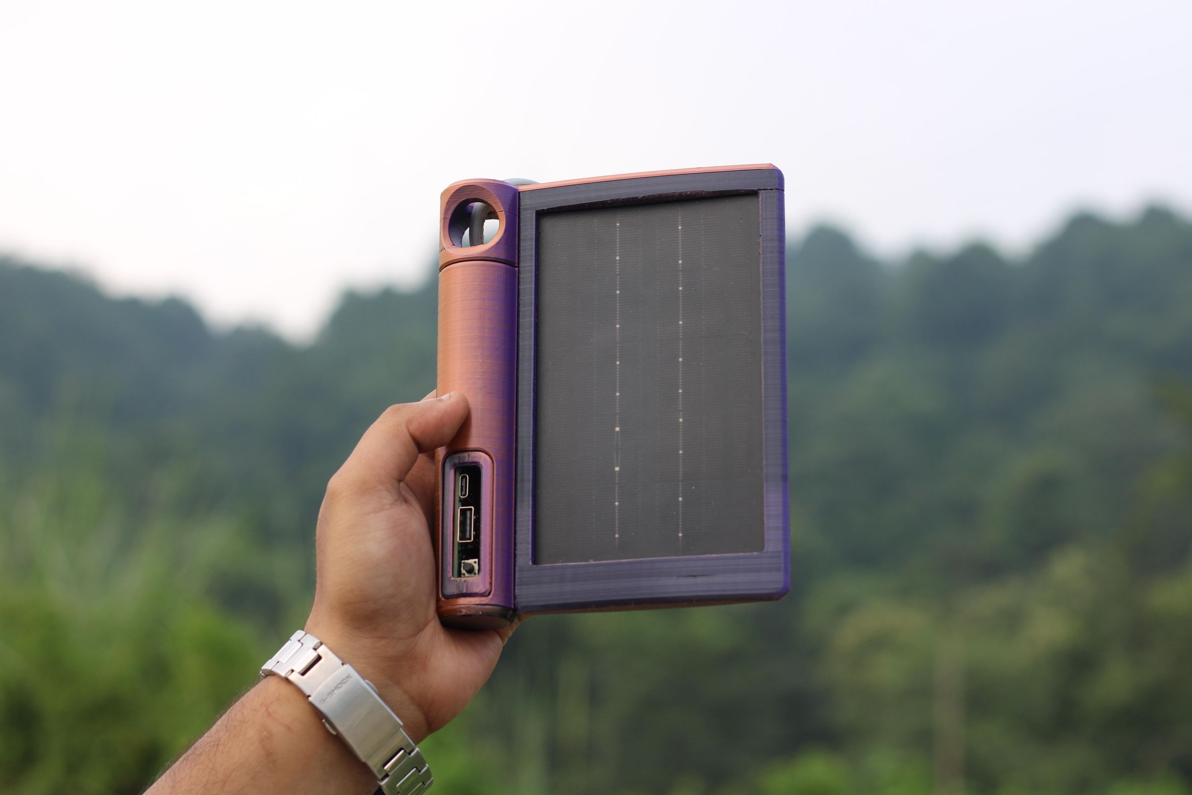
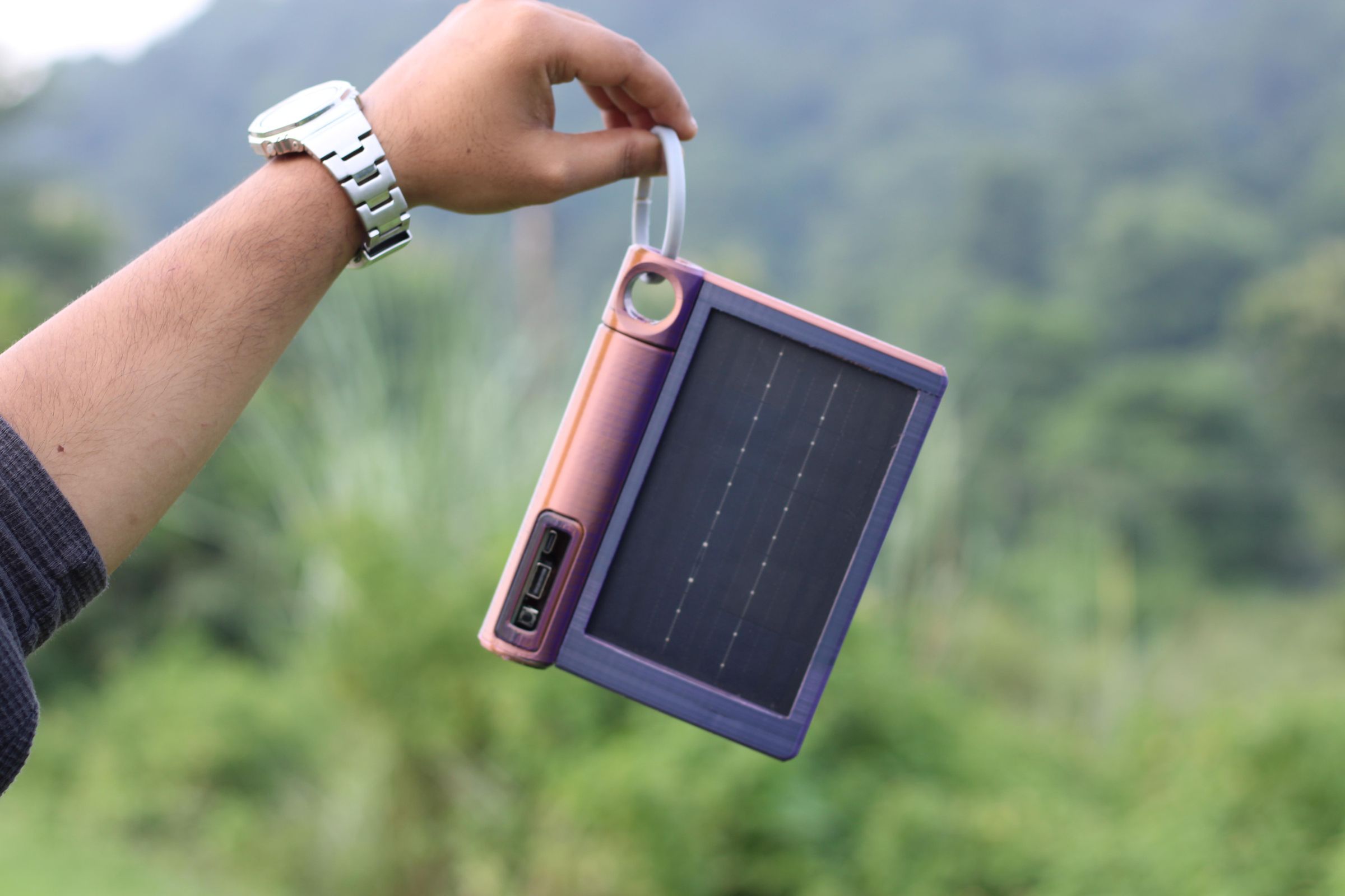
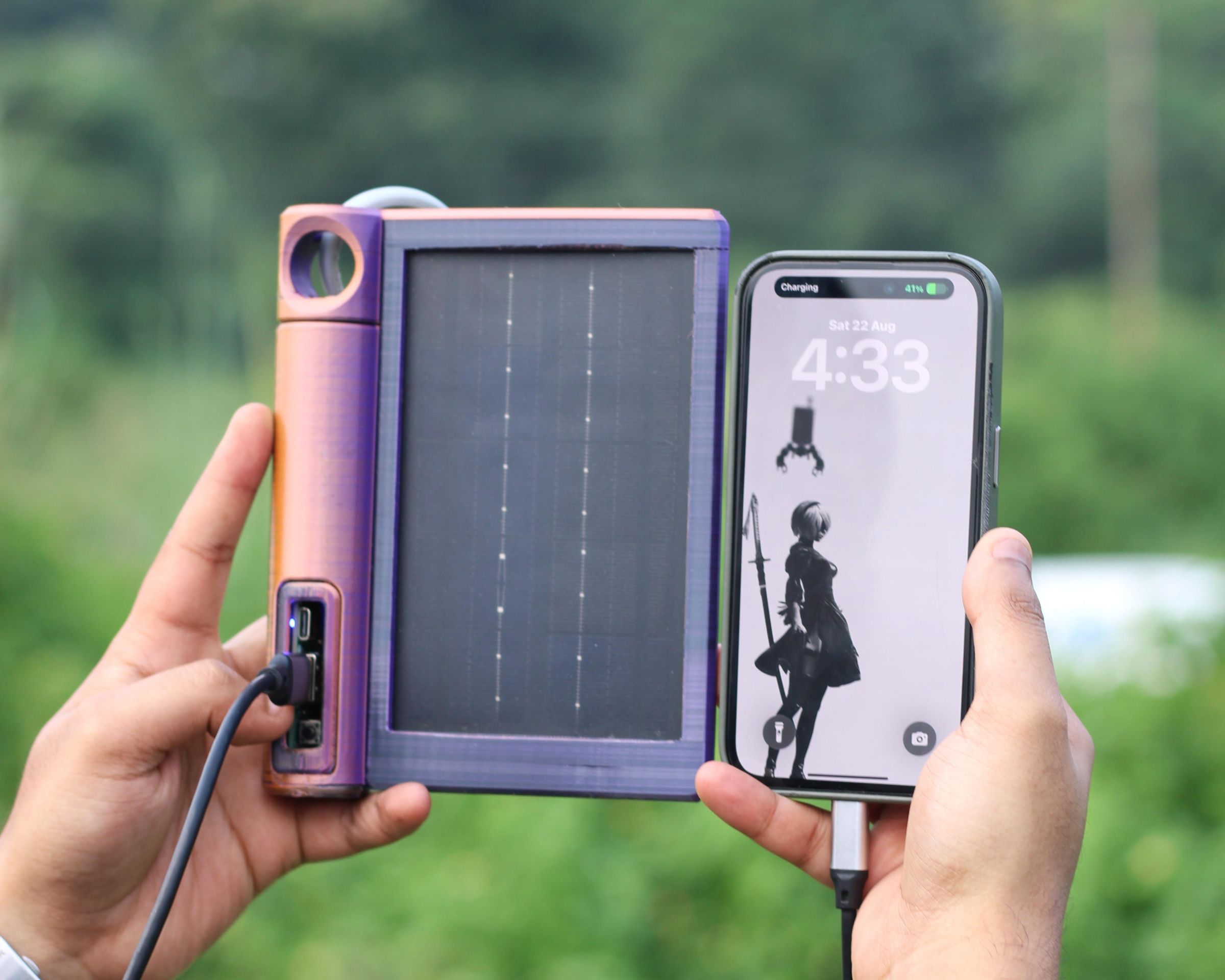
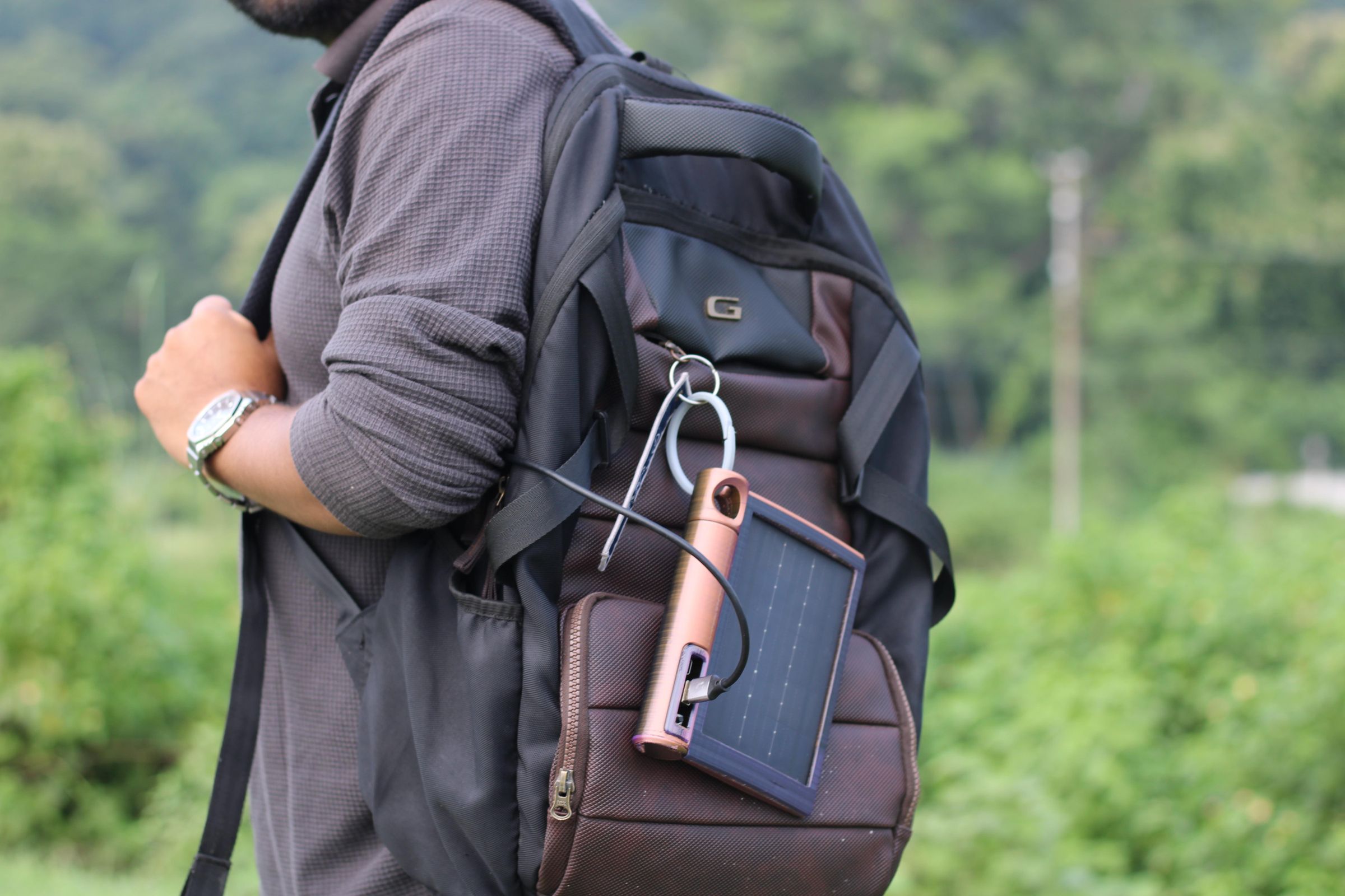
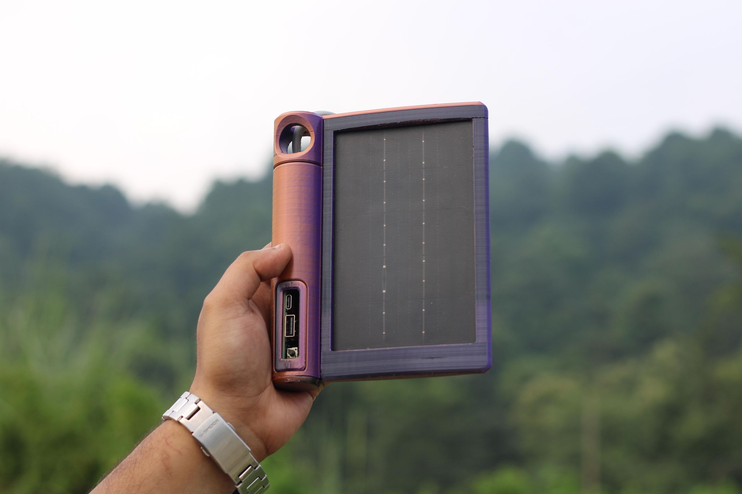
And here's the final result of this simple yet useful build: SolMate 2.0, a portable solar power bank designed for life on the move.
For general-purpose testing, I added a USB meter to the output port of SolMate, and we got a stable 5V output, which confirms that the setup is working correctly. Double-tapping the push button turns the device off.
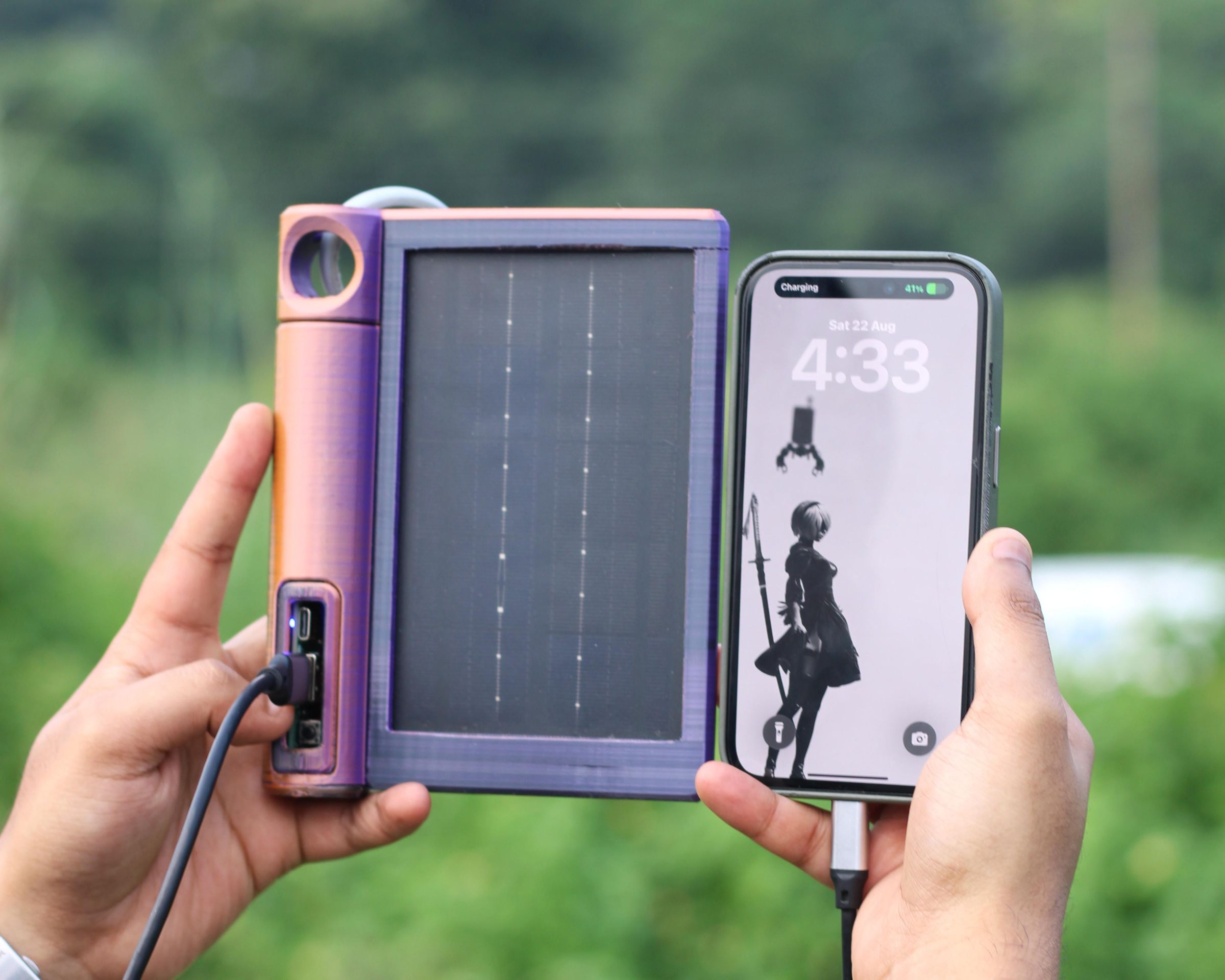
I took SolMate outside for a real-world test, clipped it onto the back of my backpack, and connected my phone to it while walking around. The 2W solar panel continuously charged the Li-ion battery, while the IP5306 power-management circuit handled the power delivery to my phone.
The whole idea is to simply clip SolMate onto your bag, plug in your phone, and let it do its job while you're on the move. There's no need to carry a bulky power bank separately, and the slim new enclosure makes it feel much more practical as an everyday outdoor companion.
The new design also gives SolMate a much cleaner and more rugged look compared to the original version. It's lightweight, compact, and honestly looks pretty cool sitting on the back of a backpack.
SolMate started as a small DIY project, but it has gradually turned into something that feels like a proper product. It does exactly what I wanted it to do—provide a simple source of backup power when I'm outdoors.
Of course, there's still plenty of room for improvement. For a future version, I'd like to add faster charging and a larger battery capacity to make SolMate even more useful.
For now, the build is complete, and all the related files are included in the attachments.
Check out Version 1 of SolMate from the link below!
https://www.hackster.io/Arnov_Sharma_makes/solmate-01165a
Thanks for making it this far, and I'll be back with a new project soon!