Solar Hydrogen Plant With Real-Time SCADA Monitoring
by noyon2004mia in Circuits > Reuse
459 Views, 5 Favorites, 0 Comments
Solar Hydrogen Plant With Real-Time SCADA Monitoring
Introduction
Electricity has become an essential part of modern life, yet many remote areas and emergency situations still face unreliable or limited access to power. Solar energy is one of the best renewable energy sources available, but one major challenge remains: the sun does not shine all the time. Instead of letting excess solar energy go to waste, it can be converted into hydrogen—a clean energy carrier that can be stored and used later.
This project demonstrates a small-scale Solar Hydrogen Plant that uses a 40W solar panel to generate hydrogen through water electrolysis. To make the system more practical and easier to understand, I also developed an ESP32-based web SCADA system that allows real-time monitoring of important operating parameters directly from a web browser. This makes it possible to observe the system's performance without needing specialized industrial equipment.
The goal of this project is not only to produce hydrogen, but also to demonstrate how renewable energy, automation, and IoT can be combined into a single educational and research platform. The system continuously monitors key operating conditions, helping users better understand the hydrogen production process while providing valuable data for future improvements.
This project is intended as a research and educational prototype. Although it is built on a small scale, the same concepts can be expanded into larger solar-powered hydrogen systems for off-grid applications, laboratories, educational institutions, and renewable energy research.
If you are interested in clean energy, hydrogen technology, ESP32, or SCADA systems, this project provides a complete walkthrough—from hardware assembly and electrical connections to programming, testing, and real-time monitoring.
Supplies


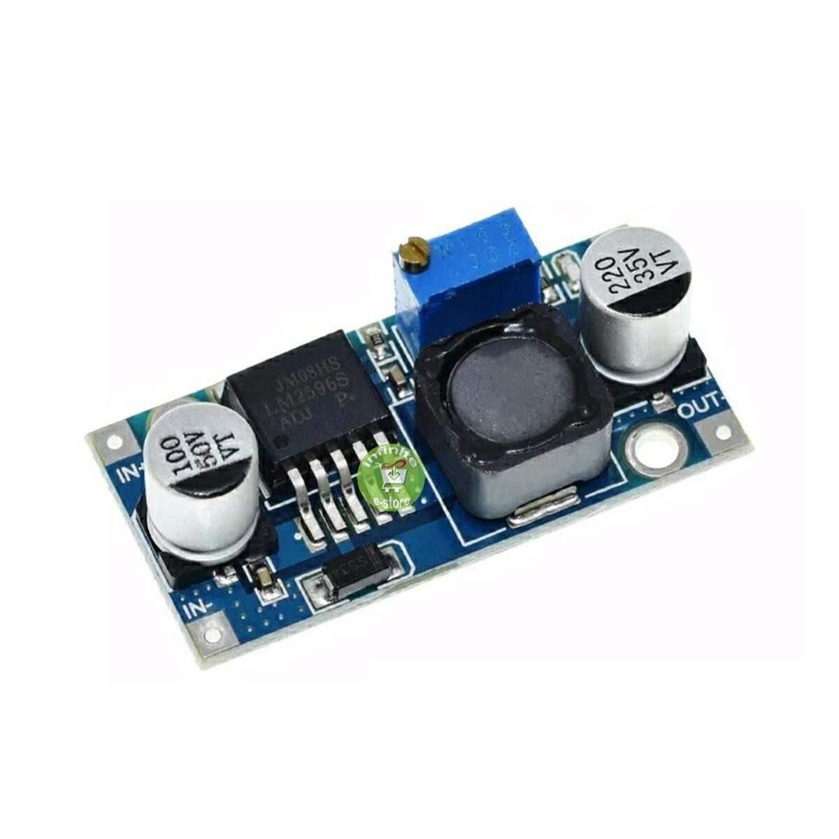
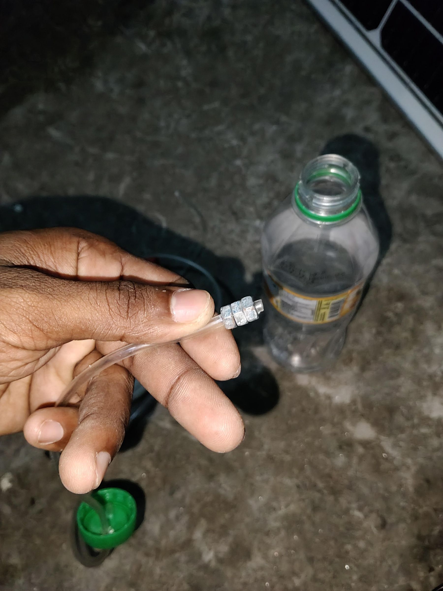
Supplies
The following components and materials were used to build this Solar Hydrogen Plant with an ESP32-based SCADA monitoring system.
Power Source
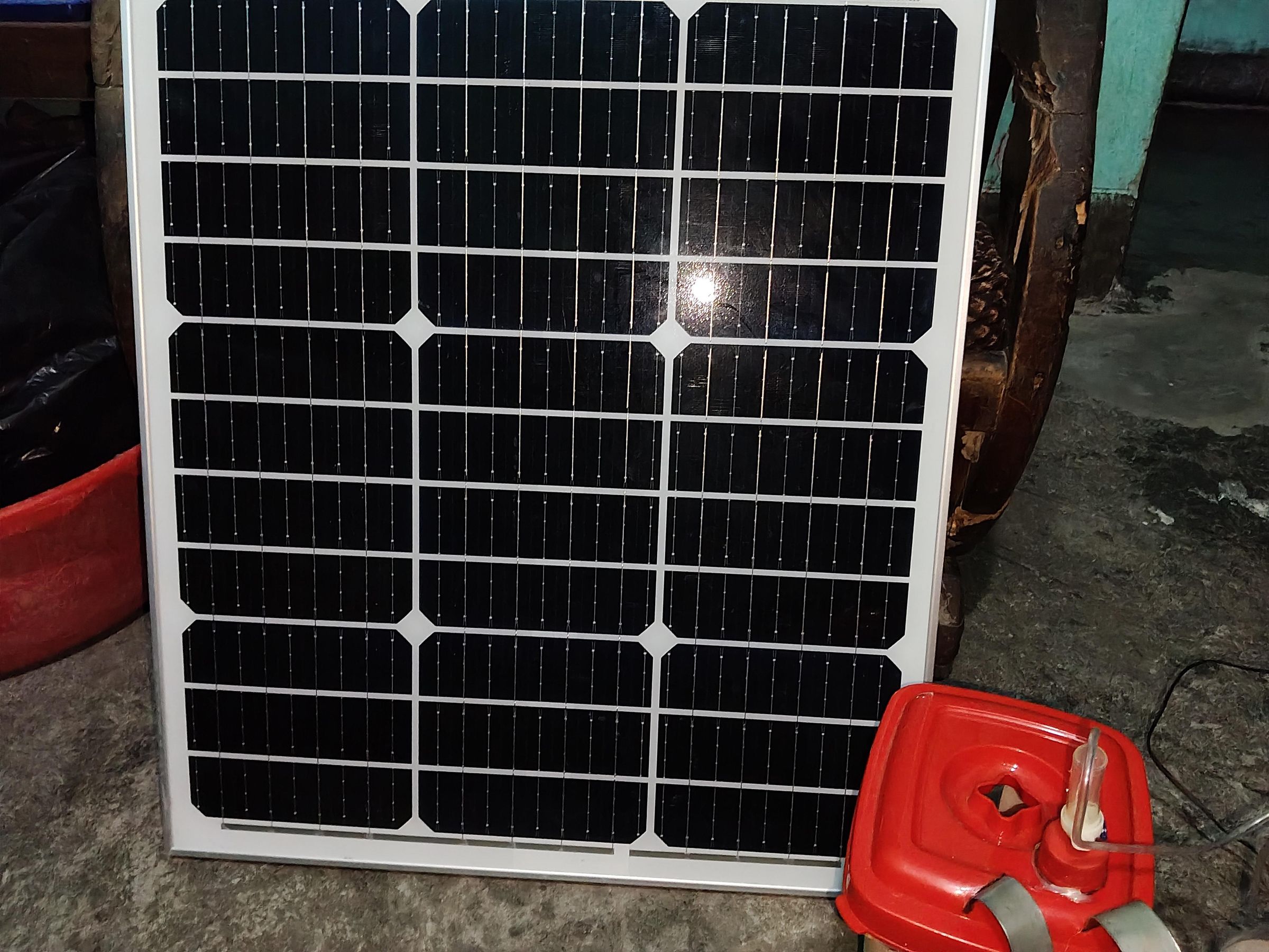
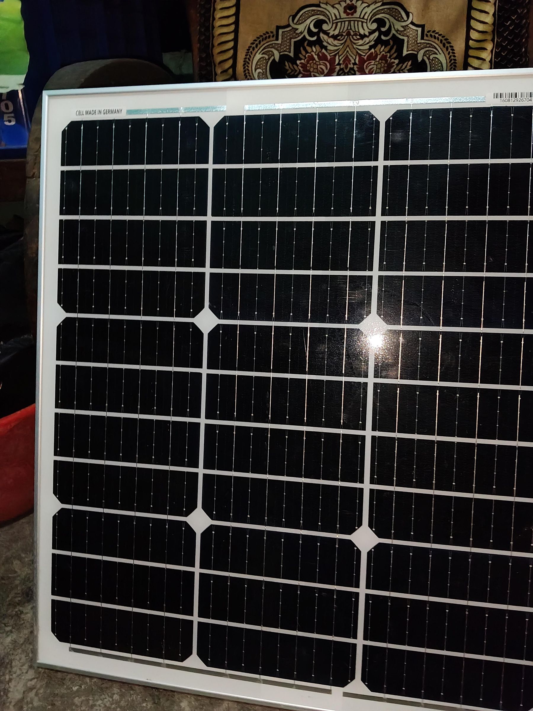
- 40W Solar Panel – Primary renewable energy source for powering the electrolyzer.
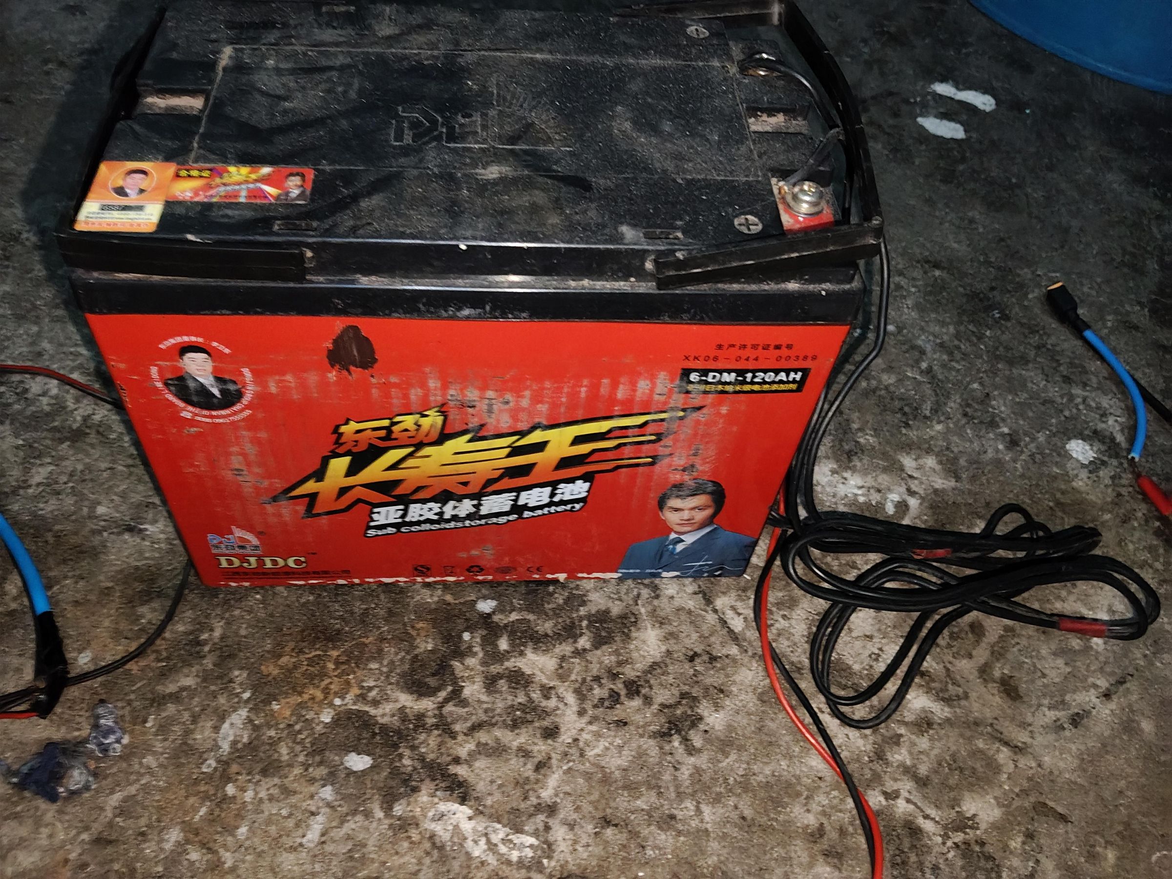
- 12V 100Ah Battery – Stores solar energy and provides stable power during operation.
Control and Monitoring System
- Voltage Regulator – Provides a stable operating voltage for the electronic circuits.
- ESP32 Development Board – Main controller for data acquisition and web-based SCADA monitoring.
- Voltage Sensor Module – Measures the system voltage in real time.
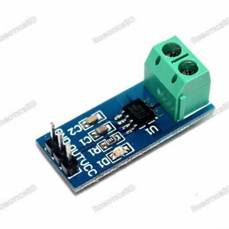
- Current Sensor Module – Monitors the current consumed by the electrolyzer.
- HX711 Pressure Sensor Module – Measures the pressure inside the hydrogen system.
- Electrical Connectors and Wires – Used for reliable electrical connections.
Mechanical Structure
- PVC Board – Used as the base platform for mounting all components.
- Super Glue – For permanent bonding of small parts.
- Hot Glue – For quick assembly and cable management.
Electrolyzer Components
- Stainless Steel Plates – Serve as the electrodes for water electrolysis.
- Stainless Steel Nuts, Bolts, and Screws – Used to assemble and secure the electrolyzer.
- Plastic Container – Acts as the electrolyzer chamber.
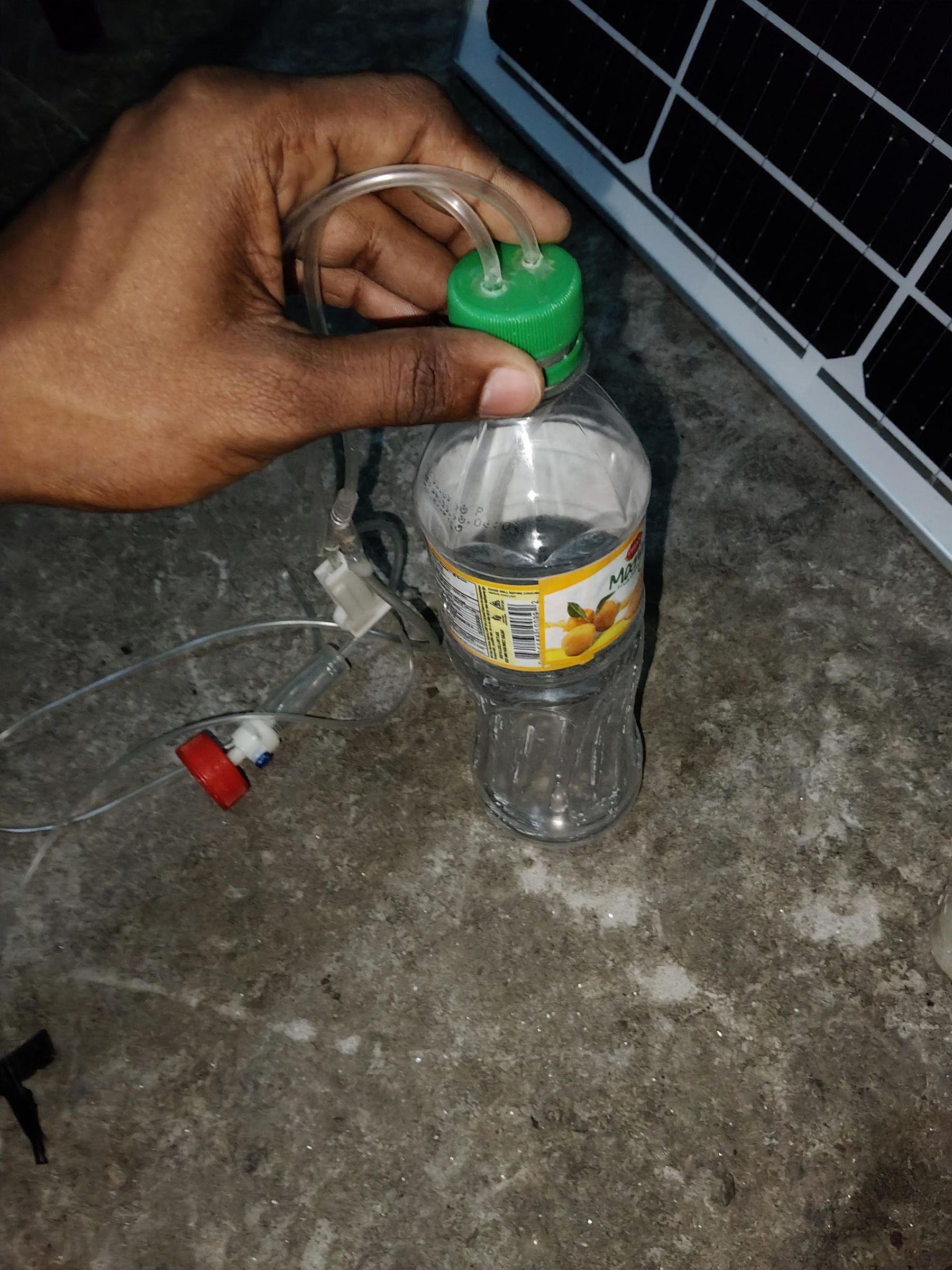
- Plastic Bottle – Used for gas collection and basic storage during testing.
Data Flow Explanation
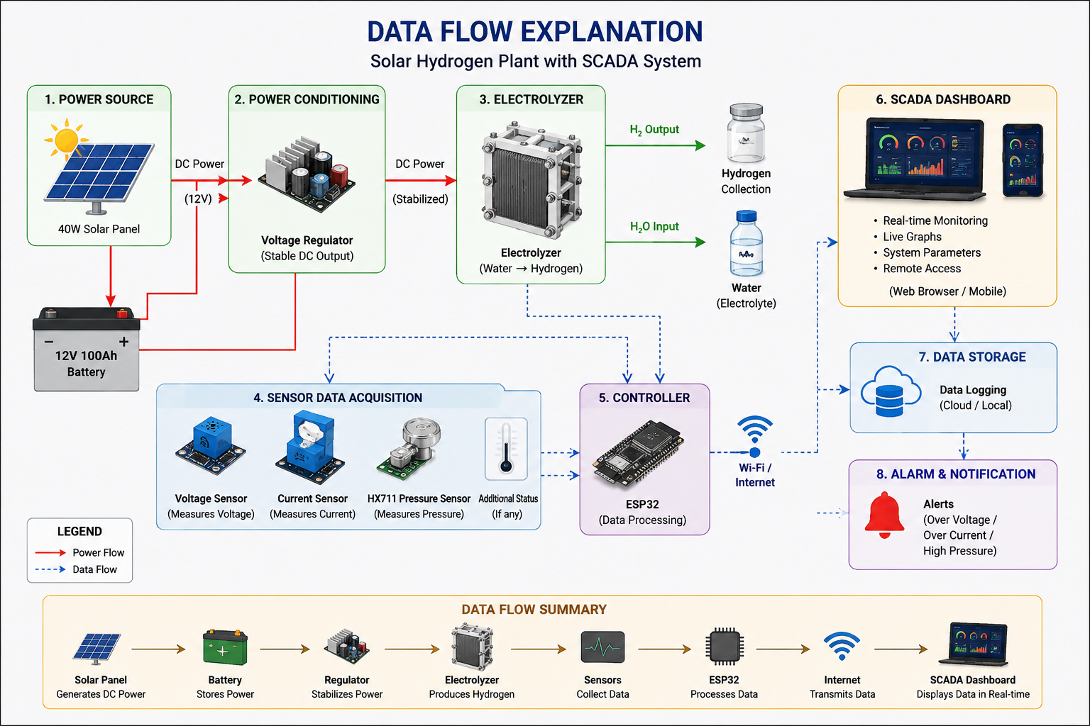
Data Flow Explanation
The system begins with a 40W solar panel, which converts sunlight into DC electrical power. This energy is stored in a 12V 100Ah battery, ensuring a stable power supply even when solar irradiance changes.
A voltage regulator provides a stable operating voltage for both the electrolyzer and the control electronics. The electrolyzer then uses electrical energy to split water into hydrogen and oxygen through the electrolysis process.
During operation, the voltage sensor continuously measures the system voltage, while the current sensor monitors the electrical current consumed by the electrolyzer. A pressure sensor (HX711-based) tracks the pressure inside the hydrogen system to help monitor operating conditions.
All sensor data is collected by the ESP32, which processes the measurements and transmits them over Wi-Fi to a web-based SCADA dashboard. The dashboard displays real-time values, allowing the user to monitor the system remotely through any web browser. This enables continuous observation of the hydrogen production process without requiring direct access to the hardware.
The SCADA system also records operational data, making it easier to analyze system performance, identify abnormal conditions, and improve future designs. By combining renewable energy, hydrogen production, real-time sensing, and IoT-based monitoring, this project demonstrates a compact and intelligent solar hydrogen research platform.
System Architecture
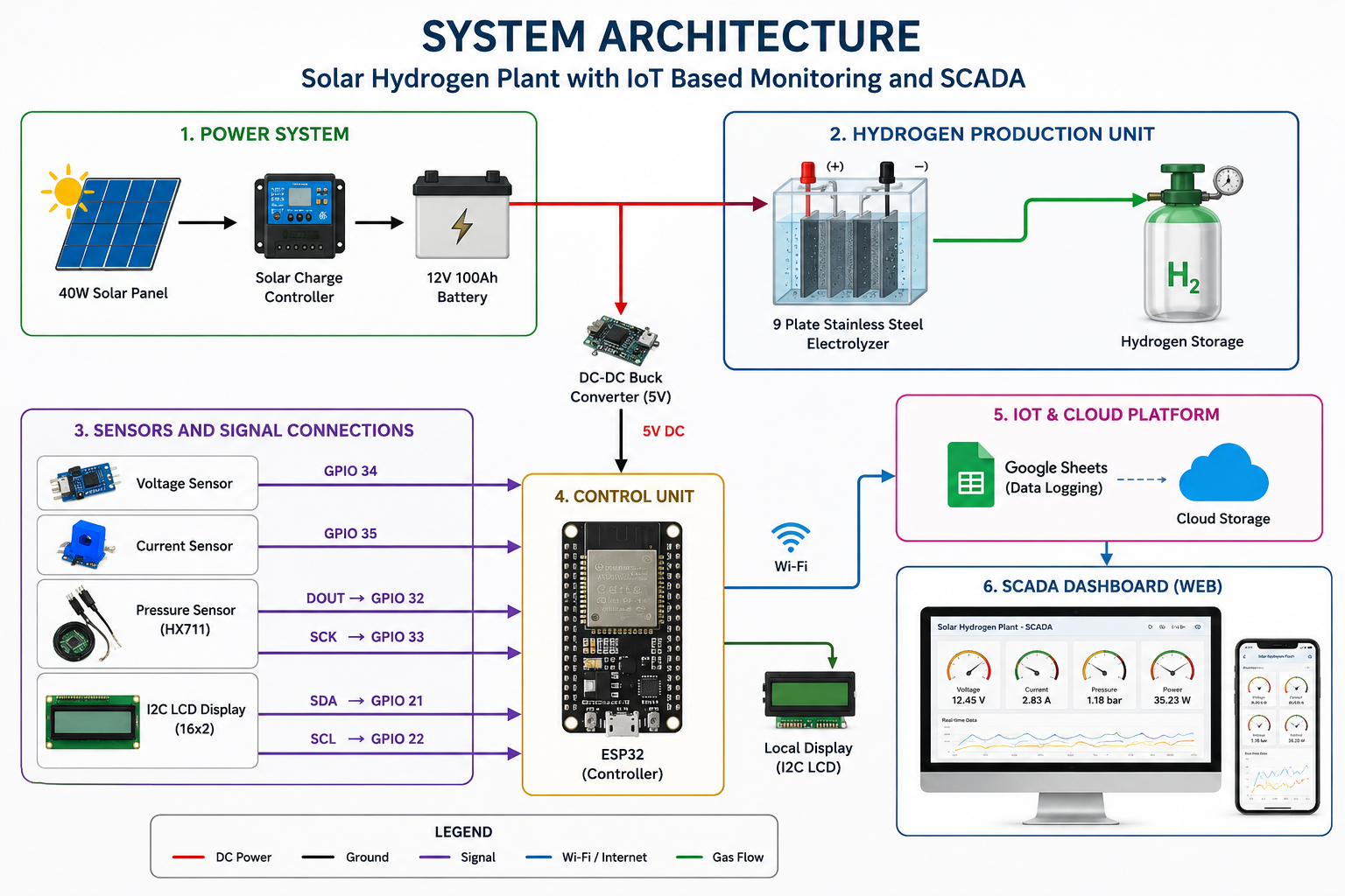
System Architecture
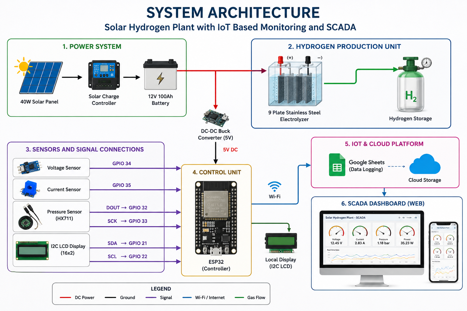
The Solar Hydrogen Plant is designed as an integrated system consisting of four main layers: the power layer, hydrogen production layer, data acquisition layer, and SCADA monitoring layer.
The power layer includes a 40W solar panel, 12V 100Ah battery, and voltage regulator. The solar panel generates DC power, the battery stores the energy for continuous operation, and the voltage regulator provides a stable power supply to the system.
The hydrogen production layer consists of the stainless-steel electrolyzer, where electrical energy is used to split water into hydrogen and oxygen through electrolysis. The generated hydrogen is collected in a storage container for demonstration and testing purposes.
The data acquisition layer continuously measures the operating condition of the system. A voltage sensor monitors the supply voltage, a current sensor measures the current consumed by the electrolyzer, and an HX711-based pressure sensing unit monitors the hydrogen system pressure. These measurements provide real-time information about the system's performance.
At the center of the architecture is the ESP32 microcontroller, which collects sensor data, processes the measurements, and communicates with the SCADA platform through Wi-Fi. The ESP32 acts as the main controller and data gateway for the entire system.
The SCADA monitoring layer displays real-time system parameters through a web-based dashboard. Users can monitor voltage, current, pressure, and overall system status from any device with a web browser. The dashboard also stores operational data, making it easier to evaluate system performance and support future improvements.
This layered architecture makes the system modular, scalable, and easy to maintain. Additional sensors, safety features, or automation functions can be integrated in the future without significant changes to the existing design.
Hardware Design and Implementation
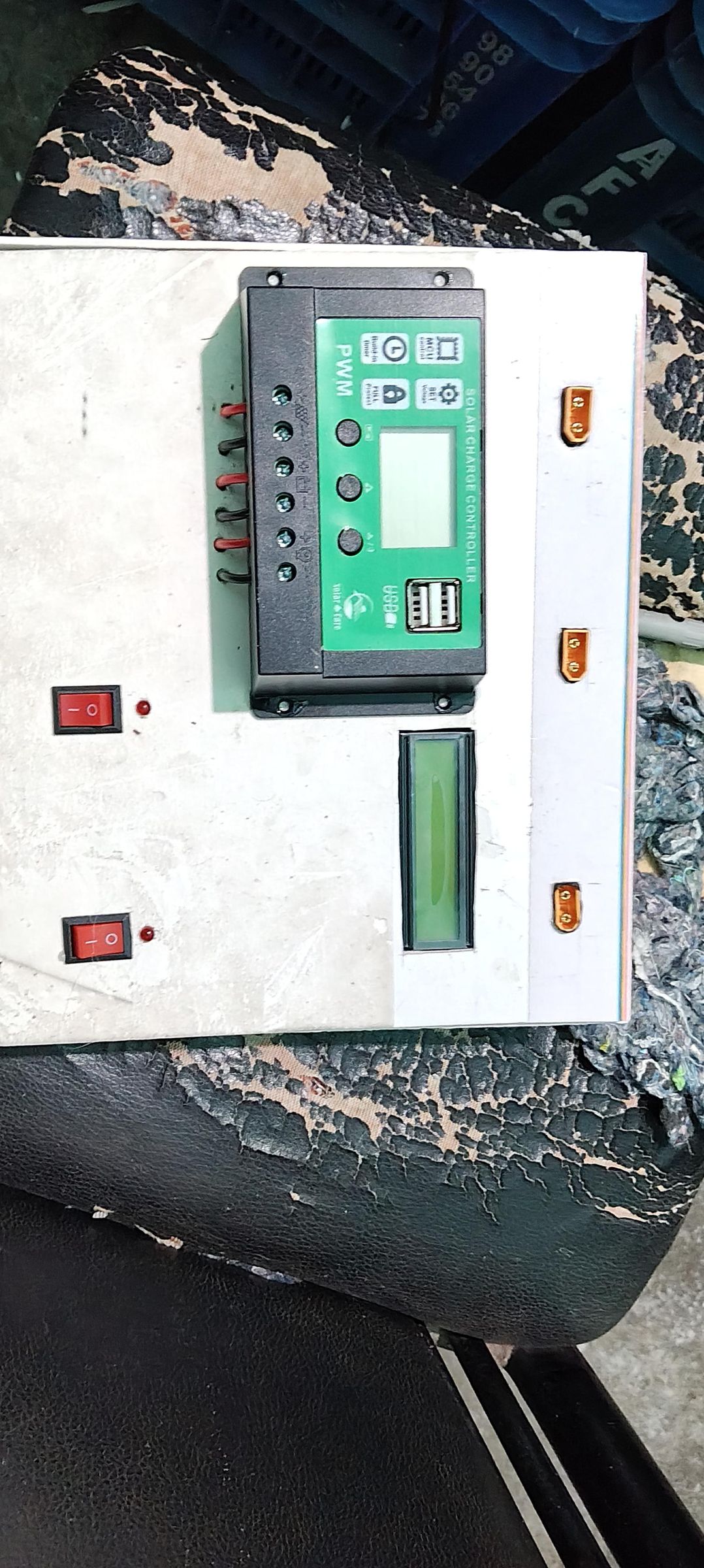
Hardware Design and Implementation
The hardware of this Solar Hydrogen Plant was designed with a strong focus on simplicity, reliability, and ease of maintenance. All components were mounted on a PVC board, creating a compact and organized structure that allows each module to be easily accessed during testing and future upgrades.
The system is powered by a 40W solar panel, which supplies renewable energy to charge a 12V 100Ah battery. The battery provides a stable power source for the electrolyzer and the electronic control system, allowing the plant to operate even when solar intensity changes. A voltage regulator is used to maintain a stable voltage for the control electronics and monitoring circuit.
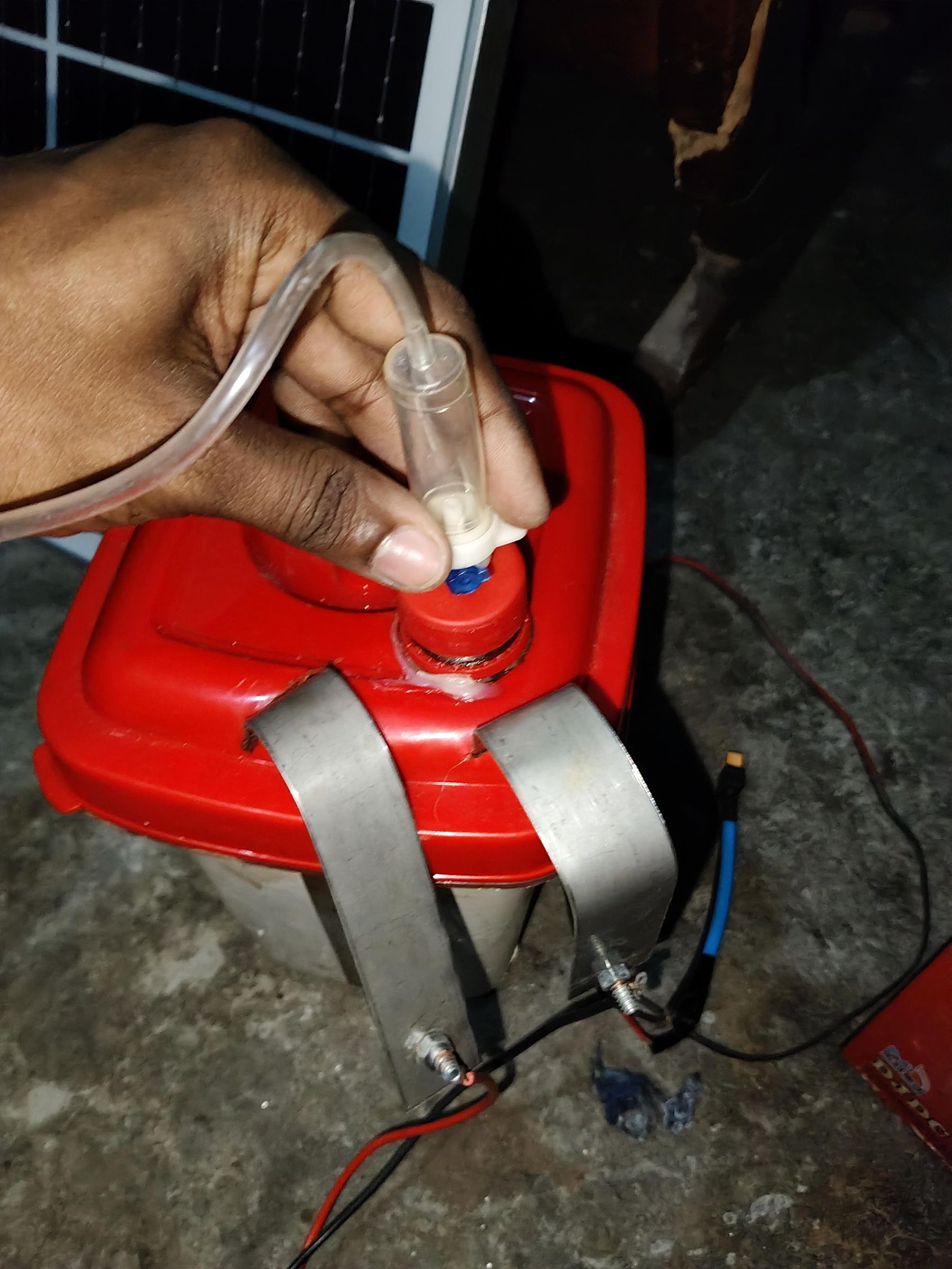
The electrolyzer was constructed using stainless steel plates as electrodes because of their durability and corrosion resistance. The electrodes were assembled with stainless steel nuts, bolts, and screws to ensure a secure mechanical structure and reliable electrical connections. A plastic container was used as the electrolysis chamber, while a plastic bottle served as the hydrogen collection chamber during testing.
For real-time monitoring, an ESP32 development board acts as the main controller. A voltage sensor measures the supply voltage, a current sensor monitors the current drawn by the electrolyzer, and an HX711-based pressure sensing unit measures the pressure inside the hydrogen system. These sensors continuously send data to the ESP32 for processing and transmission to the web-based SCADA dashboard.
Electrical connections between all modules were made using connectors and insulated wires to improve reliability and simplify maintenance. Super glue was used for permanent bonding of mechanical parts, while hot glue was applied for quick mounting, cable management, and securing lightweight components.
The completed hardware integrates the renewable power source, hydrogen production unit, sensing system, and IoT controller into a single compact platform. This modular design allows each subsystem to be tested independently while working together as a complete Solar Hydrogen Plant with real-time SCADA monitoring.
Control Box Assembly
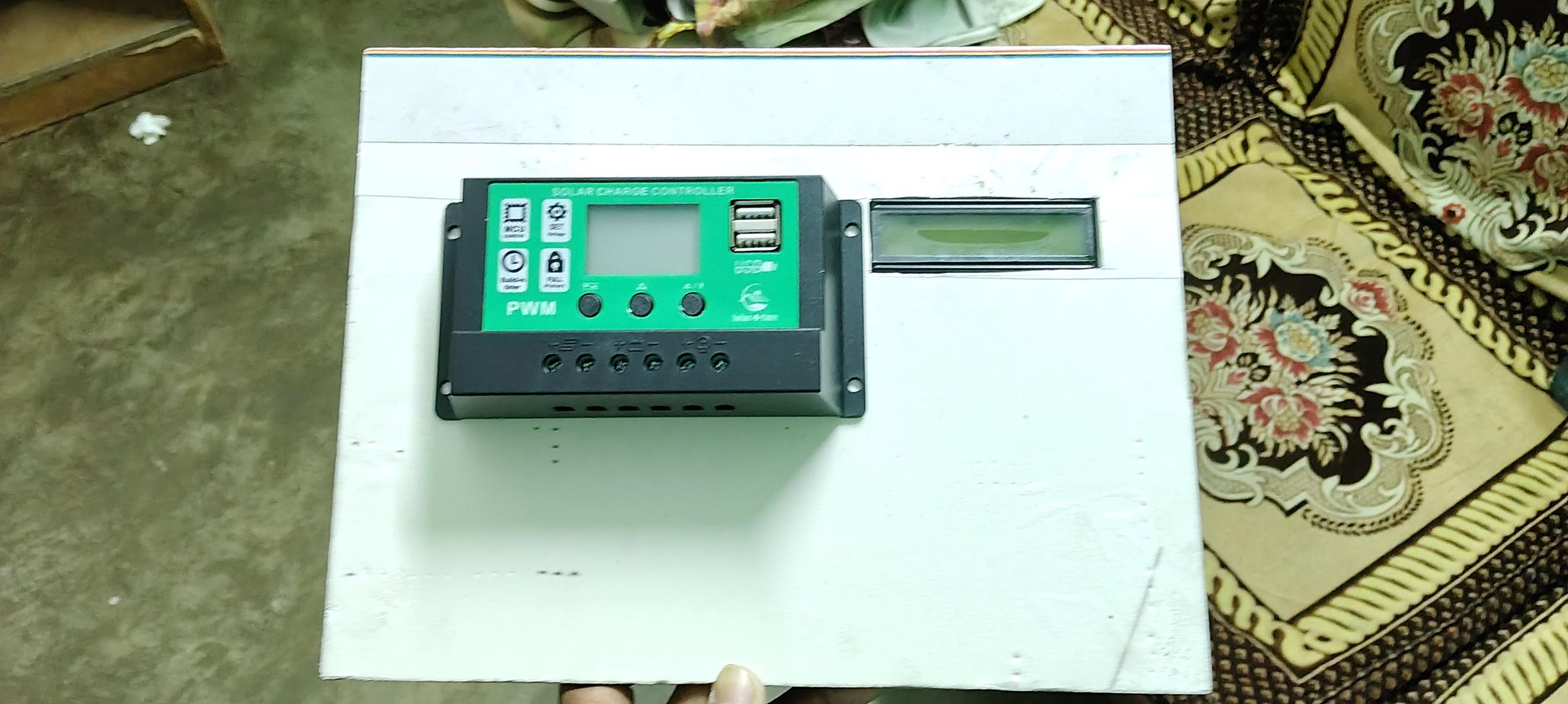
Control Box Assembly
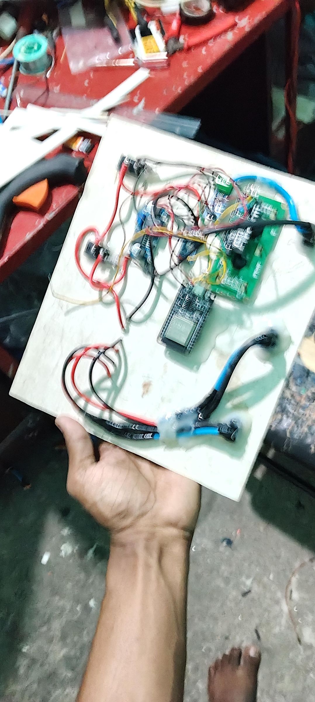
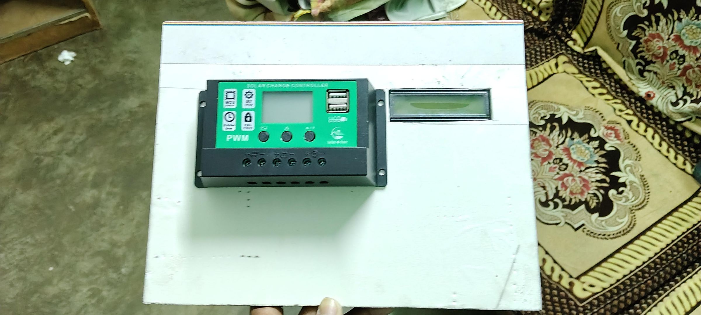
To keep the system organized, safe, and easy to maintain, all electronic components were installed inside a dedicated control box. The enclosure protects the electrical circuits from accidental contact, dust, and minor mechanical damage while providing a clean and professional appearance.
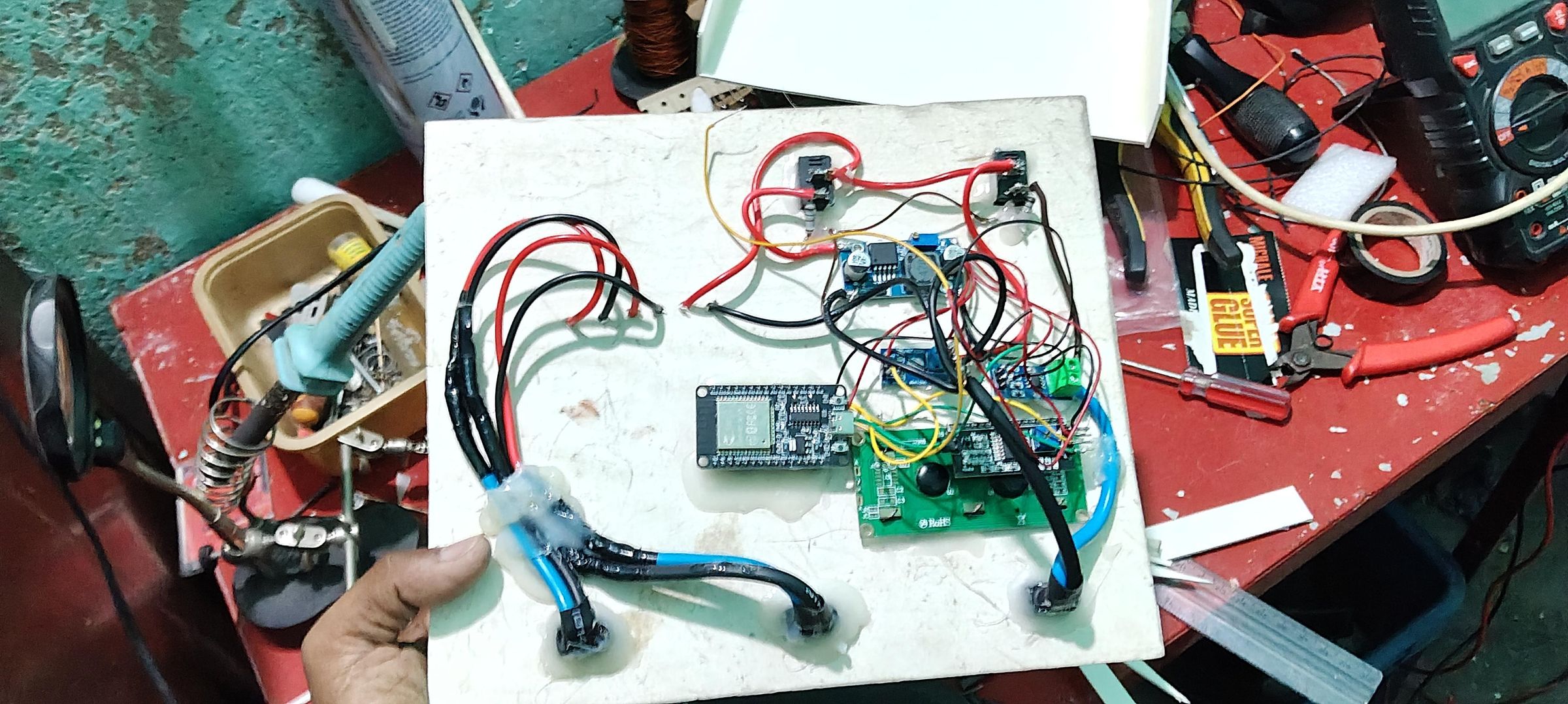
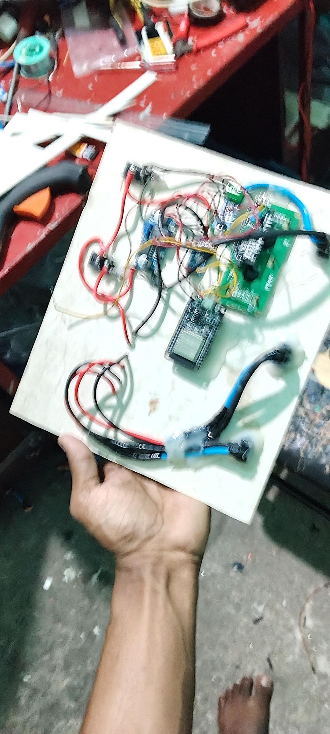
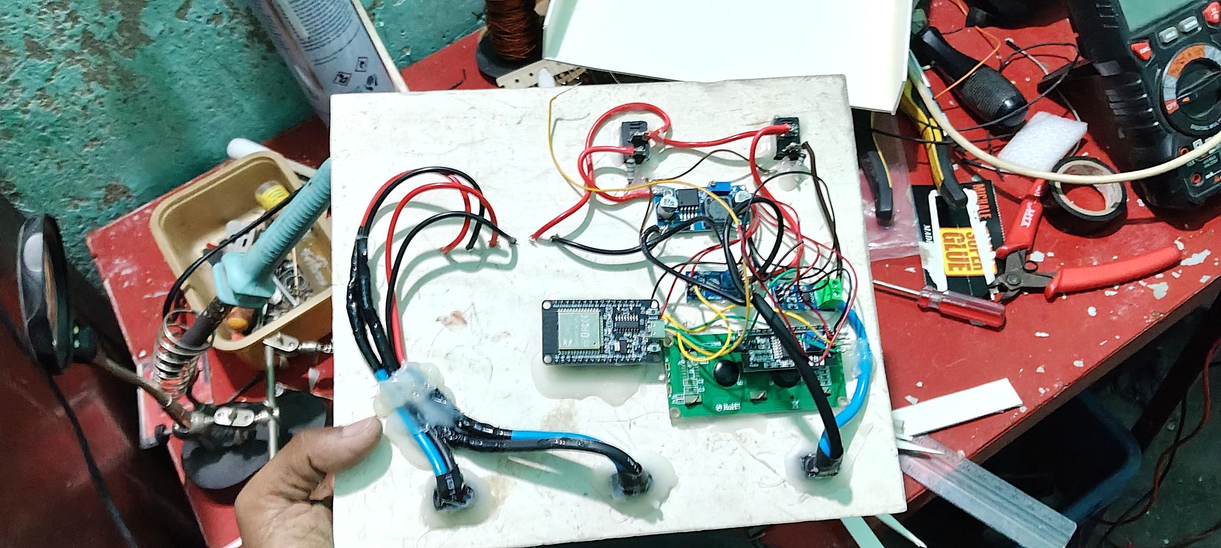
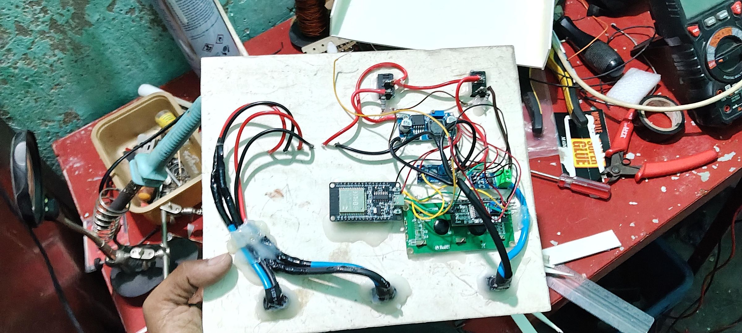
The ESP32, voltage regulator, voltage sensor, current sensor, and HX711 pressure sensing module were securely mounted inside the control box on a PVC base. The internal layout was carefully planned to ensure sufficient spacing between components, allowing proper cable routing and easier troubleshooting.
All electrical connections were made using insulated wires and connectors to improve reliability and simplify future maintenance. The input and output wires were routed through the sides of the enclosure to keep the wiring neat and reduce cable clutter. Super glue and hot glue were used where necessary to secure lightweight components and prevent movement during operation.
After completing the wiring, each connection was carefully inspected to verify correct polarity and secure electrical contact before powering the system. The finished control box serves as the central hub of the Solar Hydrogen Plant, collecting sensor data, controlling the monitoring system, and transmitting real-time information to the web-based SCADA dashboard.
Electrolyzer Design
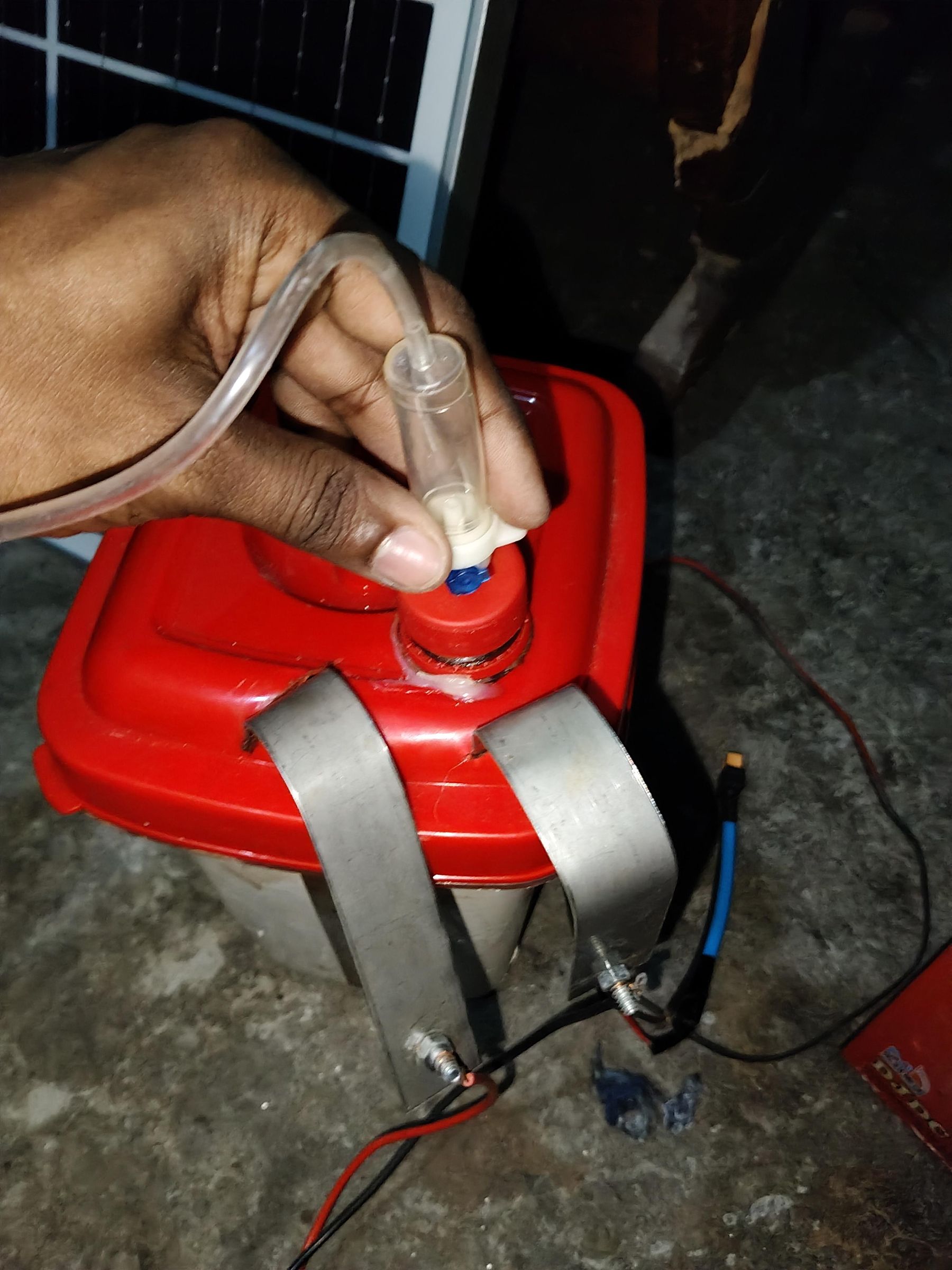
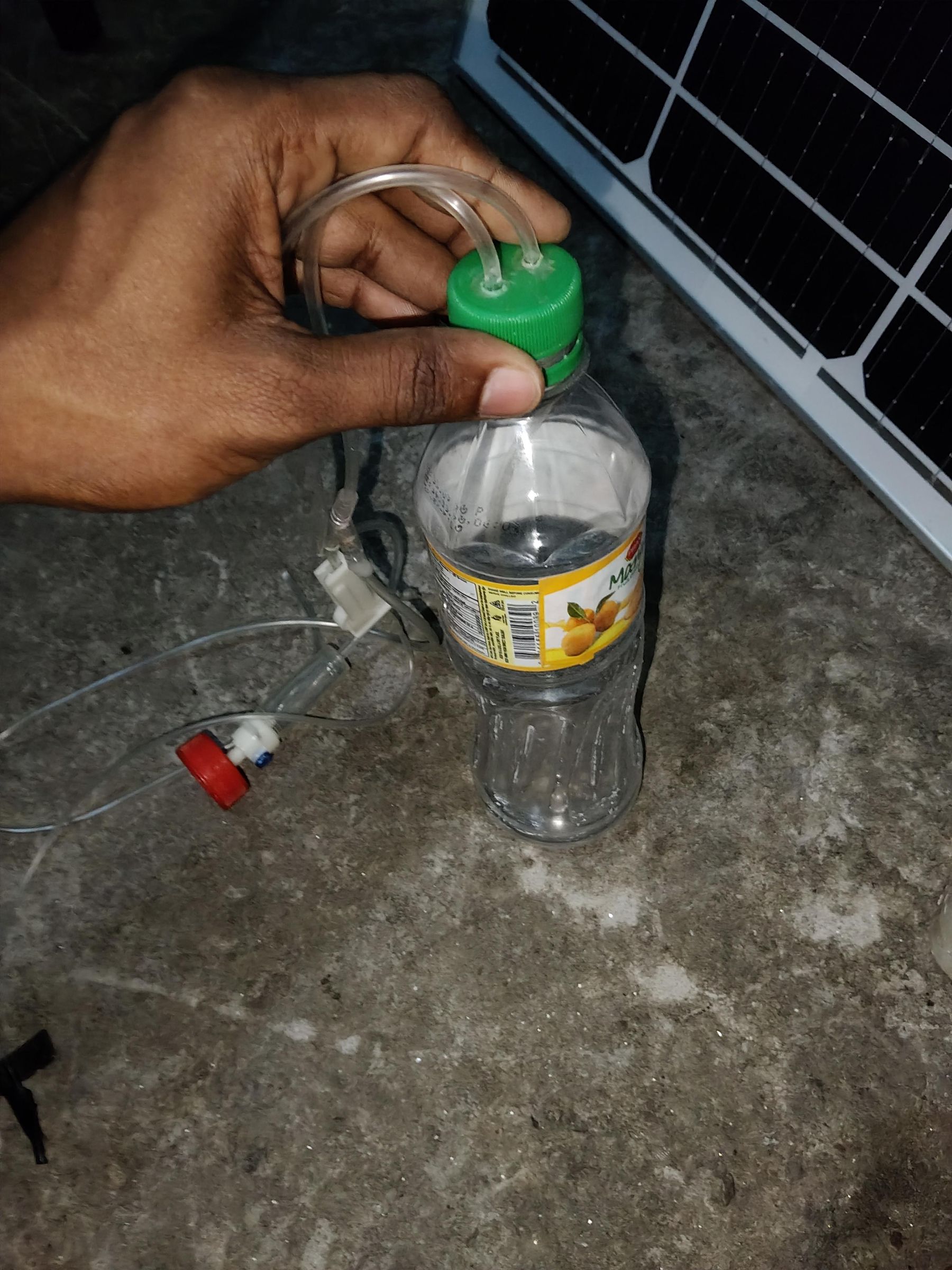
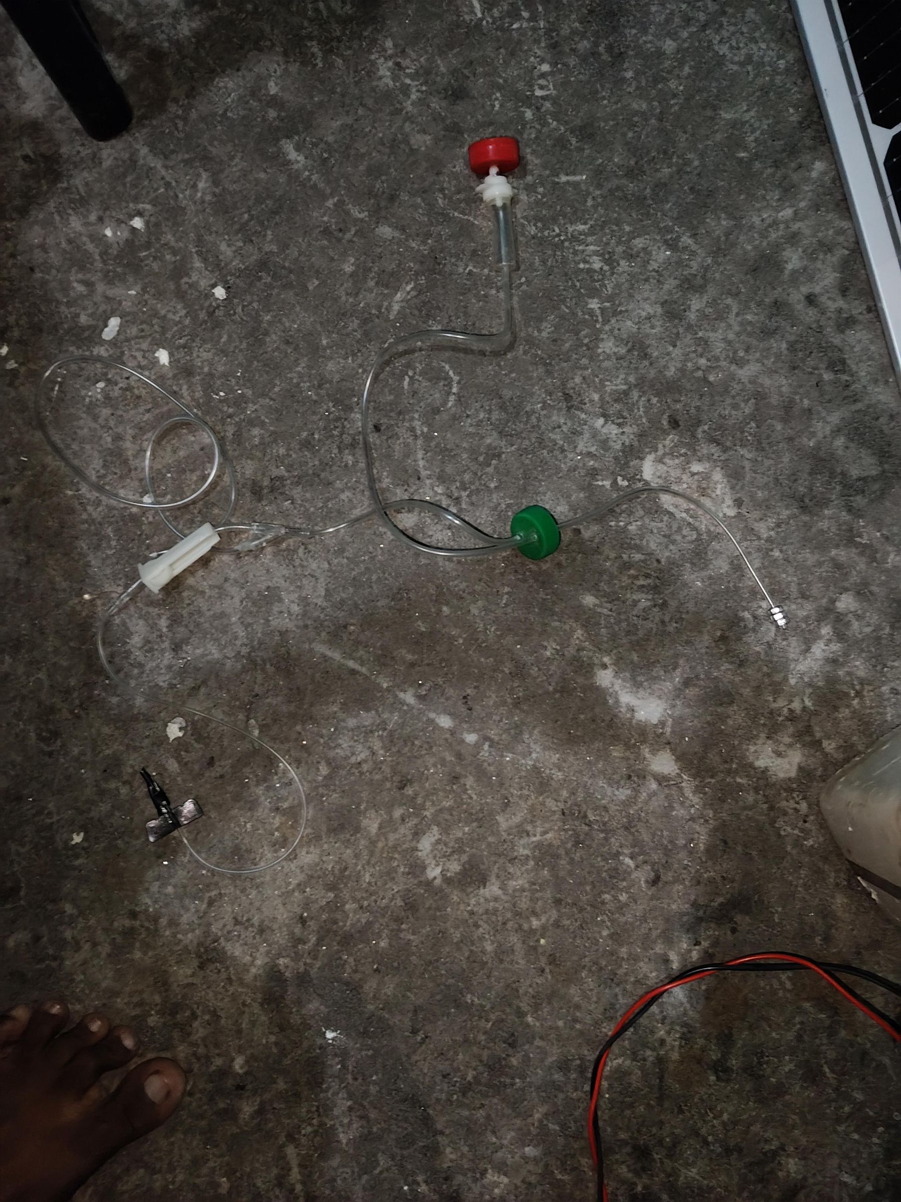
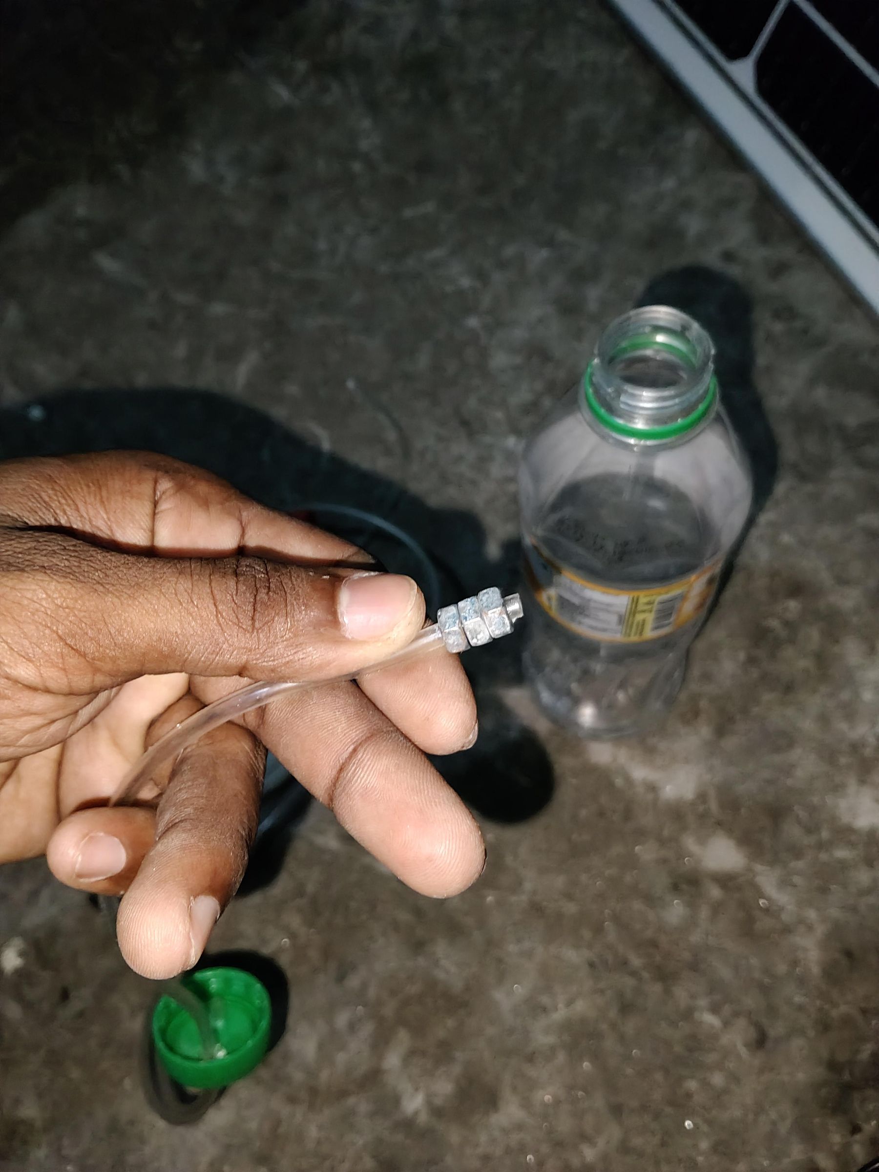
Electrolyzer Design
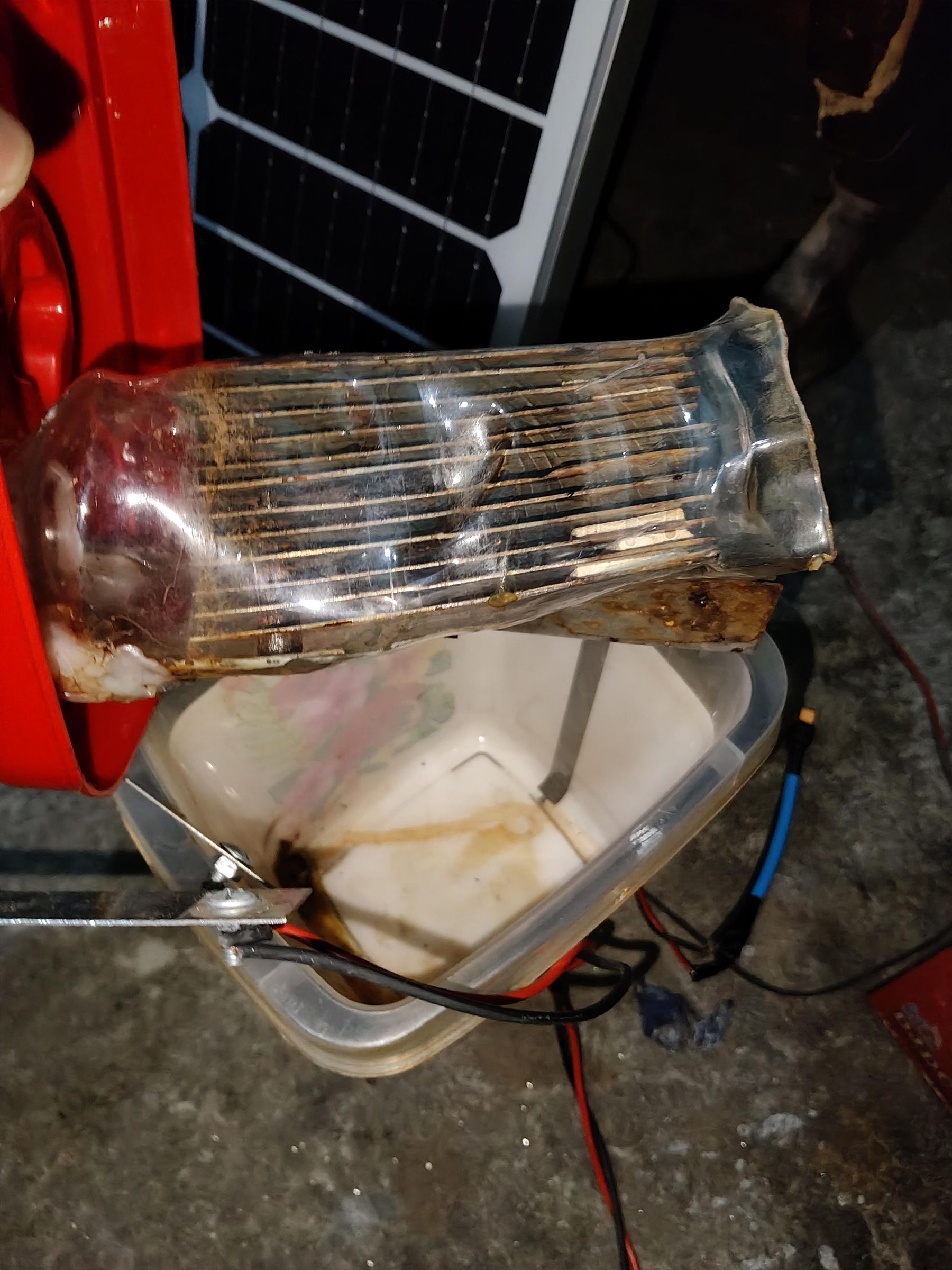
The electrolyzer is the core component of this Solar Hydrogen Plant, where electrical energy is converted into hydrogen through the electrolysis of water. The design was kept simple, low-cost, and easy to fabricate while providing a reliable platform for research and educational purposes.
The electrolyzer was built using nine stainless steel electrode plates, each measuring 2 cm × 8 cm. Stainless steel was selected because it offers good corrosion resistance, mechanical strength, and long service life in electrolysis applications. The electrode plates were carefully aligned and fixed using stainless steel nuts, bolts, and screws to maintain uniform spacing between adjacent plates and ensure a stable mechanical structure.
A plastic container was used as the electrolysis chamber because it is lightweight, electrically insulating, and resistant to water. The generated gas exits the chamber through a sealed outlet and is directed to a plastic bottle, which serves as the gas collection chamber during testing.
Special attention was given to sealing all joints and electrical connections to minimize leaks and improve operational safety. The electrode assembly was designed so that it can be easily disassembled for cleaning, inspection, or future modifications.
Although this is a small-scale prototype, the electrolyzer demonstrates the fundamental principle of hydrogen production from renewable energy. The modular design also makes it easy to increase the number or size of electrode plates in future versions to achieve higher hydrogen production rates.
Electrolyzer Connection and Calculation
Electrolyzer Connection and Calculation
The electrolyzer consists of nine stainless steel electrode plates, each measuring 2 cm × 8 cm. The plates are arranged in parallel with equal spacing to ensure uniform electrolyte flow and stable gas production. The two outer plates are connected to the DC power supply, while the remaining plates act as intermediate (bipolar) electrodes, allowing the applied voltage to be distributed across multiple electrolysis cells.
The positive terminal of the DC supply is connected to the first stainless steel plate, and the negative terminal is connected to the last plate. When the electrolyzer is energized, electric current passes through the electrolyte, causing water molecules to split into hydrogen and oxygen gas.
Electrolysis Reactions
Cathode (−): [ 2H_2O + 2e^- \rightarrow H_2 + 2OH^- ]
Anode (+): [ 4OH^- \rightarrow O_2 + 2H_2O + 4e^- ]
Overall Reaction: [ 2H_2O \rightarrow 2H_2 + O_2 ]
This means that every 2 molecules of water produce 2 molecules of hydrogen and 1 molecule of oxygen.
Electrical Power
The electrical power supplied to the electrolyzer is calculated using:
[ P = V \times I ]
Where:
- P = Power (W)
- V = Voltage (V)
- I = Current (A)
For example, if the electrolyzer operates at 12 V and 3 A:
[ P = 12 \times 3 = 36\ \text{W} ]
Hydrogen Production (Faraday's Law)
The theoretical amount of hydrogen produced is determined using Faraday's Law:
[ m = \frac{I \times t \times M}{n \times F} ]
Where:
- m = Mass of hydrogen (g)
- I = Current (A)
- t = Time (s)
- M = Molar mass of hydrogen = 2.016 g/mol
- n = Number of electrons = 2
- F = Faraday constant = 96485 C/mol
This equation provides the theoretical hydrogen production. The actual output is usually lower because of electrical, thermal, and mechanical losses.
Cell Configuration
- Number of stainless steel plates: 9
- Plate size: 2 cm × 8 cm
- Electrode material: Stainless steel
- Electrode arrangement: Multi-plate electrolyzer with bipolar intermediate plates
- Power source: 40W solar panel with 12V battery backup
The multi-plate design increases the effective electrolysis area while distributing the applied voltage across multiple cells, improving efficiency and making the electrolyzer suitable for a compact solar-powered hydrogen generation system.
Power System Design and Electrical Connections
Power System Design and Electrical Connections
The power system was designed to provide a stable and reliable energy supply for both the hydrogen production unit and the monitoring electronics. A 40W solar panel serves as the primary renewable energy source and charges a 12V 100Ah battery, ensuring continuous operation even when solar irradiance is low. A voltage regulator is used to provide a stable operating voltage for the ESP32 and the sensing circuits.
The electrolyzer is powered directly from the DC power system, while the monitoring circuit continuously measures the operating parameters without interrupting the hydrogen production process. This arrangement allows the system to generate hydrogen while simultaneously collecting real-time performance data.
ESP32 Pin Connections
The ESP32 acts as the central controller of the system. All sensors and the display are connected according to the following pin assignments:
Component ESP32 Pin
Voltage Sensor Output
GPIO 34 (ADC)
Current Sensor Output
GPIO 35 (ADC)
HX711 DOUT
GPIO 32
HX711 SCK
GPIO 33
I2C LCD SDA
GPIO 21
I2C LCD SCL
GPIO 22
Electrical Connections
Power Supply
- 40W Solar Panel → Battery charging circuit
- 12V 100Ah Battery → Main DC power source
- Voltage Regulator → Supplies regulated voltage to the ESP32 and sensor modules
Voltage Measurement
The voltage sensor is connected across the DC supply to continuously monitor the system voltage. The sensor output is connected to GPIO 34, allowing the ESP32 to read the voltage through its analog-to-digital converter (ADC).
Current Measurement
The current sensor is installed in series with the electrolyzer power line to measure the operating current. Its analog output is connected to GPIO 35 of the ESP32.
Pressure Measurement
The hydrogen system pressure is monitored using an HX711-based pressure sensing unit. The communication pins are connected as follows:
- HX711 DOUT → GPIO 32
- HX711 SCK → GPIO 33
The ESP32 continuously reads pressure data and displays it on the SCADA dashboard.
LCD Display
A 16×2 I2C LCD provides local monitoring of the system parameters. The display is connected using the I2C interface:
- SDA → GPIO 21
- SCL → GPIO 22
This display shows real-time voltage, current, pressure, and system status without requiring a computer or mobile device.
System Operation
During operation, the solar panel supplies energy to the battery and the electrolyzer. The voltage sensor, current sensor, and pressure sensor continuously collect operating data. The ESP32 processes these measurements, updates the LCD display, and transmits the data to the web-based SCADA dashboard over Wi-Fi. This architecture enables simultaneous hydrogen production, local monitoring, and remote real-time supervision from any web browser.
Database Schema
Database Schema
The SCADA system stores all monitoring data in a cloud database, allowing real-time visualization, historical analysis, and remote access through a web browser. Each record contains a timestamp together with the measured operating parameters of the Solar Hydrogen Plant.
Database Structure
Field Name Data Type Description
timestamp
DateTime
Date and time of the recorded data
voltage
Float
Solar/battery voltage (V)
current
Float
Electrolyzer current (A)
pressure
Float
Hydrogen system pressure
power
Float
Calculated power consumption (W)
systemStatus
String
Current operating status (Running/Idle/Fault)
Data Flow
- The voltage sensor, current sensor, and pressure sensor continuously collect real-time measurements.
- The ESP32 reads the sensor values and calculates the system power using the measured voltage and current.
- The processed data is transmitted over Wi-Fi to the cloud database.
- The SCADA dashboard retrieves the latest records from the database and displays them in real time.
- Historical data is stored for performance analysis, troubleshooting, and future system improvements.
Example Database Record
This database schema provides a simple, scalable, and efficient structure for storing operational data while supporting real-time monitoring, historical logging, and performance evaluation of the Solar Hydrogen Plant.
IoT-Based Monitoring System
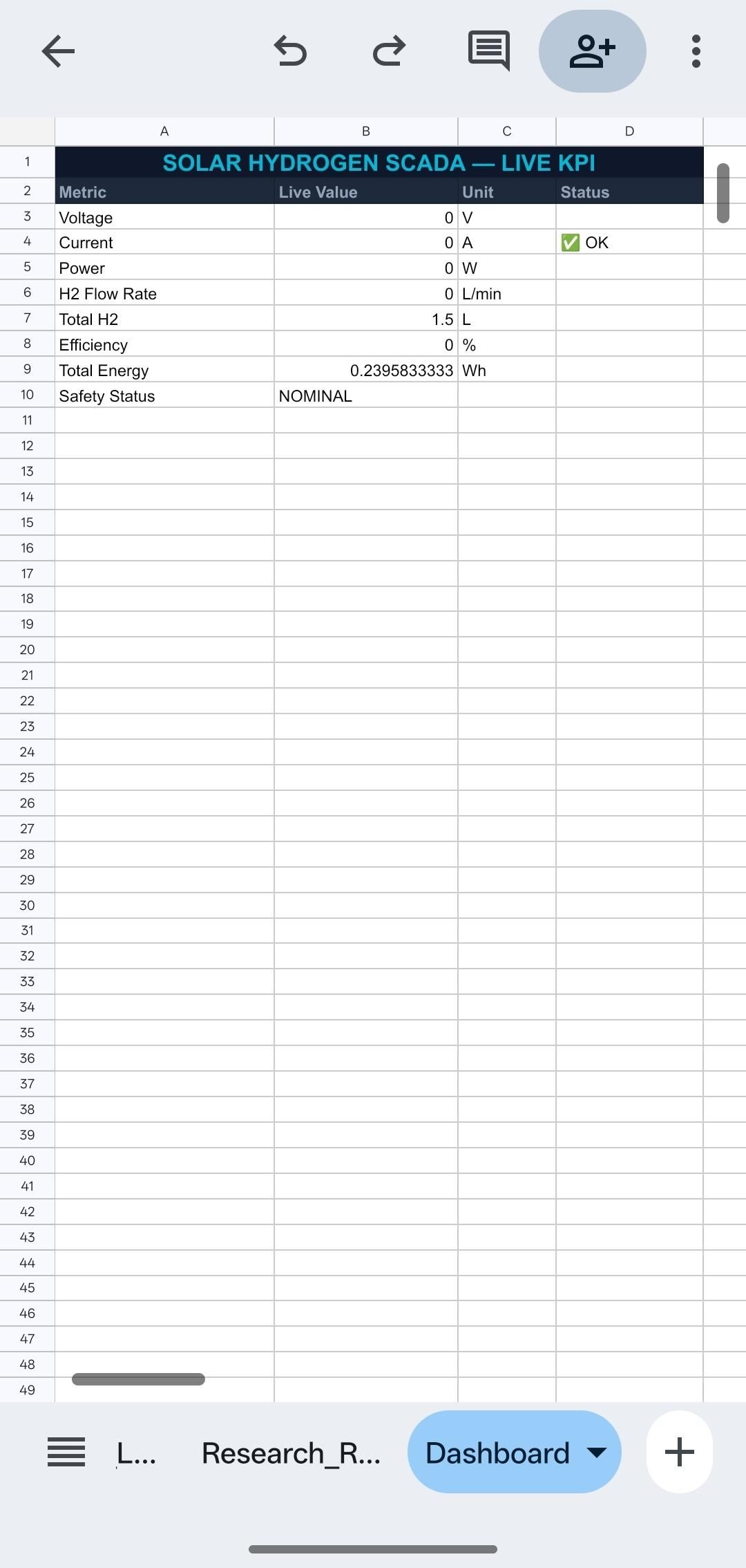
IoT-Based Monitoring System
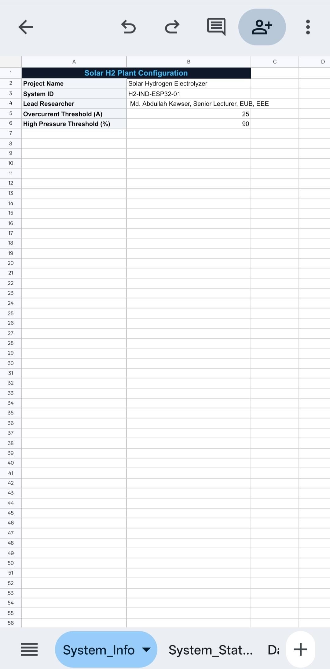
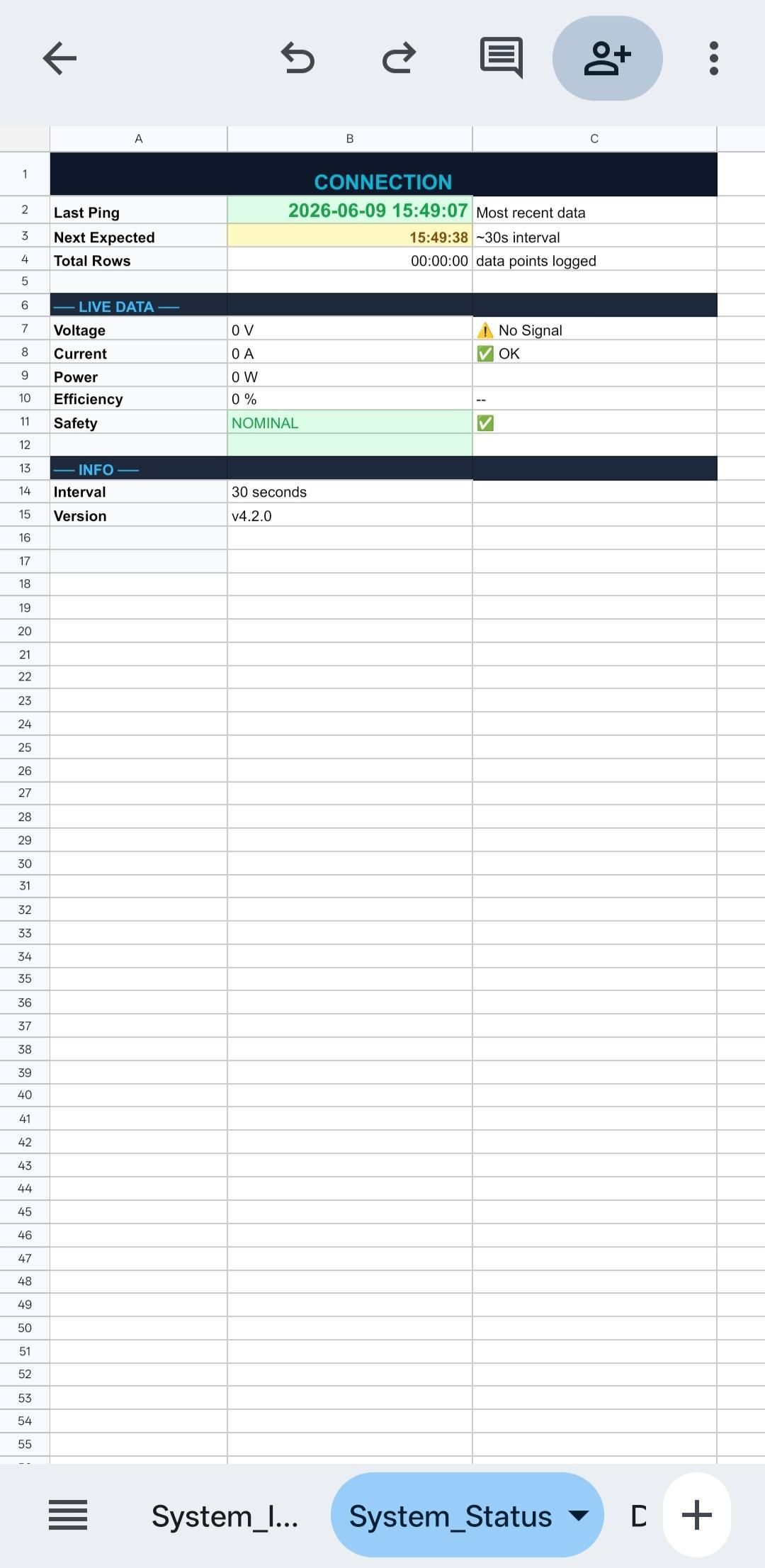
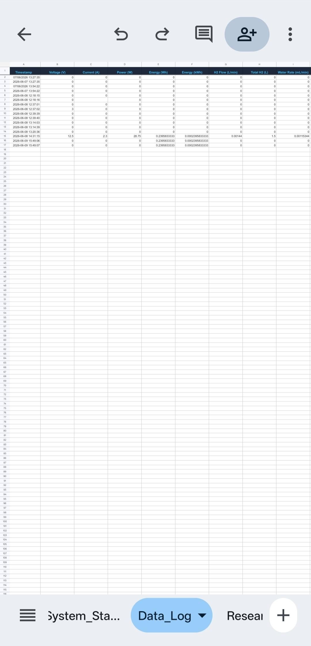
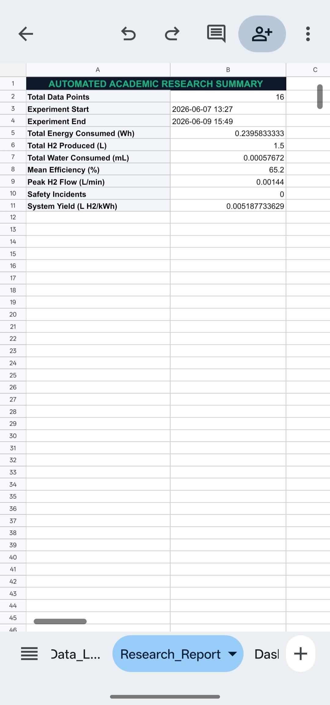
To enable real-time remote monitoring, this project uses an ESP32-based IoT system that uploads operating data directly to Google Sheets over Wi-Fi. This cloud-based approach provides a simple and cost-effective way to record, monitor, and analyze the performance of the Solar Hydrogen Plant without requiring dedicated SCADA software.
The ESP32 continuously collects data from the voltage sensor, current sensor, and HX711-based pressure sensing unit. After processing the measurements, the controller sends the data to Google Sheets using an internet connection. Each new reading is automatically stored as a new row together with its timestamp, creating a complete history of the system's operation.
Because the data is stored in Google Sheets, the system can be monitored from any smartphone, tablet, or computer with a web browser. This makes it easy to observe live operating conditions, review previous measurements, and analyze system performance from virtually anywhere with internet access.
The Google Sheets database also serves as a research log, allowing long-term data collection and performance evaluation. Recorded values can be used to compare different operating conditions, calculate system efficiency, identify abnormal behavior, and support future improvements to the hydrogen production system.
By combining the ESP32, Wi-Fi communication, and Google Sheets, this project demonstrates a practical IoT-based monitoring solution that is reliable, low-cost, and easy to implement for renewable energy research and educational applications.
Software Technologies
Software Technologies
The software architecture of this project was developed to provide reliable control, real-time data acquisition, cloud-based monitoring, and an easy-to-use user interface. The ESP32 serves as the main controller, reading sensor data, processing measurements, and transmitting information to the cloud through a Wi-Fi connection.
The firmware was developed using the Arduino IDE, which provides a simple and efficient environment for programming the ESP32. Sensor data from the voltage sensor, current sensor, and HX711 pressure sensing unit are continuously acquired, filtered, and processed before being uploaded.
For IoT communication, the ESP32 connects to a Wi-Fi network and automatically sends real-time data to Google Sheets, creating a cloud-based database for continuous monitoring and historical data logging.
A web-based SCADA dashboard was developed to display important operating parameters, including system voltage, current, pressure, calculated power, and overall system status. The dashboard retrieves the latest information from the cloud, allowing users to monitor the Solar Hydrogen Plant remotely using any device with a web browser.
Software Tools Used
- Arduino IDE – ESP32 firmware development and programming.
- ESP32 Arduino Framework – Microcontroller programming and peripheral control.
- Google Sheets – Cloud database for data logging and storage.
- Web-Based SCADA Dashboard – Real-time monitoring and visualization.
- Wi-Fi Communication – Wireless data transmission between the ESP32 and the cloud.
- HTML, CSS, and JavaScript – Development of the browser-based monitoring interface.
This software architecture combines embedded programming, IoT communication, cloud data storage, and web visualization into a complete monitoring platform, making the Solar Hydrogen Plant easy to operate, monitor, and analyze for research and educational purposes.
Primary Automation Rules
Primary Automation Rules
The Solar Hydrogen Plant operates automatically based on a set of predefined control rules to ensure stable operation, reliable monitoring, and continuous data logging. The ESP32 continuously reads sensor data, evaluates the operating conditions, and updates the monitoring system in real time.
Automation Rules
Rule 1: System Initialization
- When power is applied, the ESP32 initializes all sensors and establishes a Wi-Fi connection.
- The LCD and monitoring system display the current system status.
Rule 2: Continuous Sensor Monitoring
- The ESP32 continuously reads:
- Voltage Sensor
- Current Sensor
- Pressure Sensor (HX711)
- Sensor readings are updated at regular intervals.
Rule 3: Real-Time Data Processing
- The controller processes all sensor values and calculates the electrical power using:
- Power = Voltage × Current
- The processed data is prepared for local display and cloud transmission.
Rule 4: IoT Data Logging
- The ESP32 automatically uploads voltage, current, pressure, power, and timestamp data to Google Sheets through the Wi-Fi network.
- Each measurement is stored as a new record for future analysis.
Rule 5: Local Display Update
- The LCD continuously displays the latest operating parameters, allowing users to monitor the system directly from the control box.
Rule 6: Web-Based Monitoring
- The SCADA dashboard automatically refreshes and displays the latest sensor readings, enabling remote monitoring from any web browser.
Rule 7: Pressure Monitoring
- The pressure sensor continuously monitors the hydrogen system pressure.
- If the measured pressure exceeds the predefined safe operating limit, the system indicates an abnormal operating condition so that the operator can take appropriate action.
Rule 8: Continuous Operation
- The monitoring process repeats continuously while the system is powered, ensuring uninterrupted data acquisition, cloud logging, and real-time supervision.
These automation rules provide reliable system operation by integrating sensor monitoring, IoT communication, cloud data logging, local display, and web-based SCADA into a single automated control system.
Deployment and Testing
Deployment and Testing
After completing the hardware assembly and software configuration, the Solar Hydrogen Plant was deployed for functional testing under real operating conditions. The objective was to verify the performance of the power system, electrolyzer, sensors, ESP32 controller, IoT communication, and the web-based SCADA monitoring system.
The 40W solar panel was connected to the 12V 100Ah battery, which supplied stable power to the electrolyzer and control electronics. Before starting the experiment, all electrical connections, sensor wiring, and mechanical joints were carefully inspected to ensure safe and reliable operation.
During testing, the electrolyzer successfully produced hydrogen through water electrolysis while the ESP32 continuously measured the system voltage, current, and hydrogen pressure. These values were displayed locally on the LCD and simultaneously transmitted via Wi-Fi to Google Sheets, creating a real-time cloud-based data log.
The web-based SCADA dashboard was tested using a standard web browser to verify remote monitoring. The dashboard successfully displayed live operating parameters, while the Google Sheets database recorded each measurement with its corresponding timestamp. This allowed the system performance to be monitored and reviewed from any internet-connected device.
Several test runs were performed to evaluate system stability and data consistency. The recorded measurements confirmed reliable sensor operation, continuous IoT communication, and accurate cloud data logging throughout the testing period.
Overall, the deployment demonstrated that the integrated Solar Hydrogen Plant operated successfully as a compact renewable energy research platform. The combination of hydrogen production, real-time sensing, cloud-based data logging, and browser-based SCADA monitoring provides a practical foundation for future development of larger and more advanced solar hydrogen systems.
Conclusion
Conclusion
This project demonstrates how renewable energy, hydrogen production, IoT, and real-time monitoring can be integrated into a single, low-cost research platform. By using a 40W solar panel, a 12V 100Ah battery, a stainless-steel electrolyzer, and an ESP32-based monitoring system, I successfully developed a compact Solar Hydrogen Plant capable of producing hydrogen while continuously monitoring its operating conditions.
One of the main achievements of this project is the integration of a web-based SCADA system with Google Sheets, allowing voltage, current, pressure, and power data to be monitored and recorded in real time from any internet-connected device. This not only improves system supervision but also creates valuable experimental data for future research and performance analysis.
Although this prototype is built on a small scale, it demonstrates the fundamental concept of converting solar energy into hydrogen as a clean and storable energy source. The modular design makes it easy to expand the system with larger solar panels, higher-capacity electrolyzers, improved hydrogen storage, and additional safety features.
This project has also provided valuable hands-on experience in renewable energy systems, electrolysis, embedded systems, IoT communication, cloud data logging, and SCADA development. It highlights how affordable components can be combined to create an educational and research-oriented platform for exploring sustainable energy technologies.
I hope this project encourages students, makers, and renewable energy enthusiasts to experiment with hydrogen technology and develop innovative solutions for future clean energy systems. While there is still significant room for improvement, this prototype serves as an important step toward building smarter, safer, and more efficient solar-powered hydrogen production systems.