Solar-Powered Danger Detection & Alert System
by shouryajangir in Circuits > Microcontrollers
138 Views, 1 Favorites, 0 Comments
Solar-Powered Danger Detection & Alert System
Many dangerous situations give some kind of physical or environmental warning before they become serious.
The problem is that a person may not always be watching the area continuously.
So I designed and built a small standalone danger detection and warning system.
The system continuously monitors its sensor. When the measured signal becomes abnormal, the Arduino calculates a danger intensity level and displays it on a 3-digit 7-segment display.
At the same time, an audible alarm is activated.
The alarm frequency can change according to the detected danger level, making the warning more noticeable.
The device also has a manual alarm-stop button, allowing the user to silence the alarm after noticing the warning.
The entire system is powered using a solar panel, making it suitable for locations where continuous access to mains electricity may not be available.
Supplies
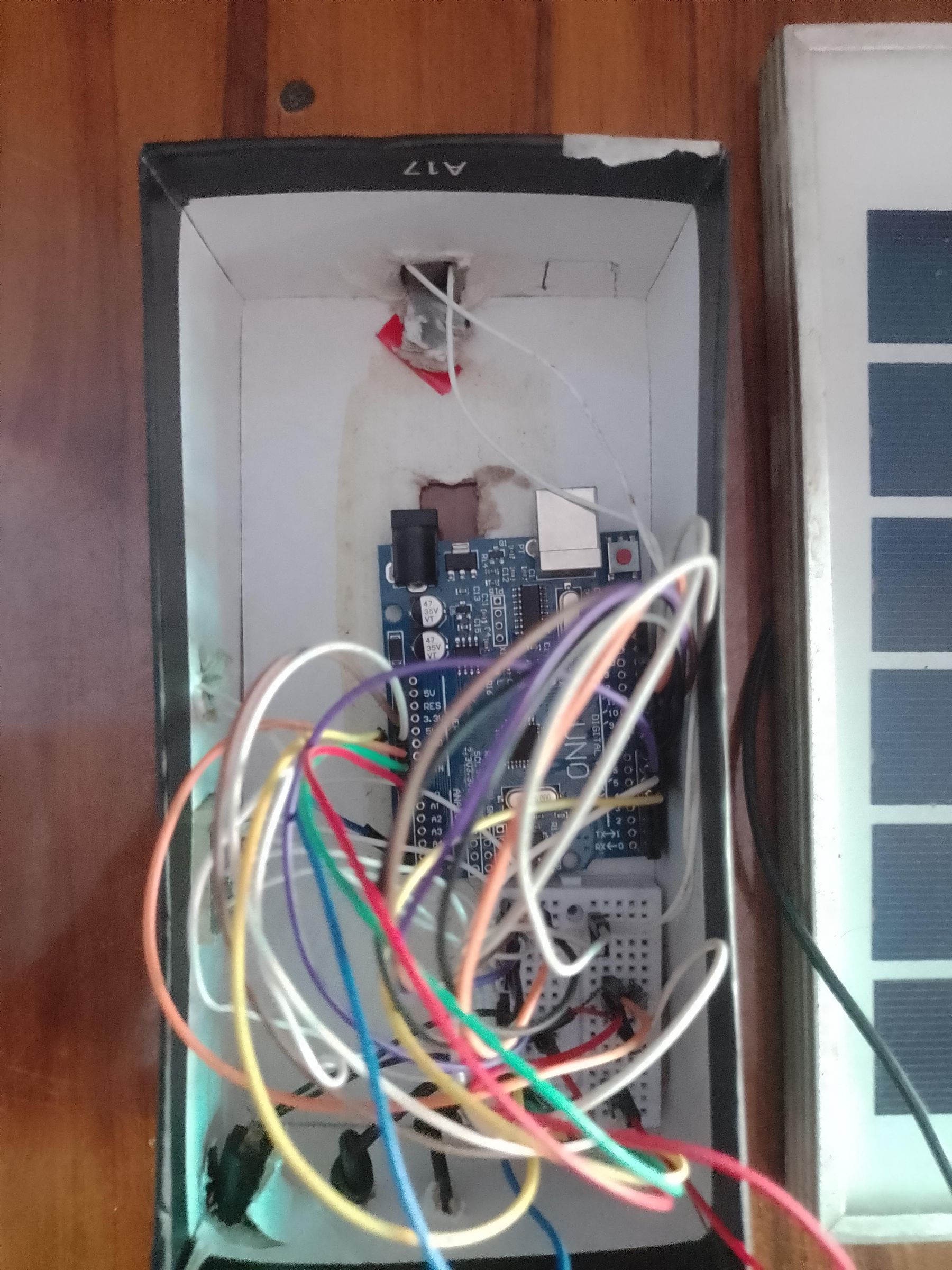
Electronics
Arduino UNO
3-digit 7-segment display
Sensor
Buzzer/speaker
Push button
Resistors
Jumper wires
Breadboard
Solar panel
Suitable power regulation/charging circuitry
Connecting wires
Mechanical parts
Spring
Metal pipe/tube
Cardboard/enclosure material
Tape/glue
Small mounting hardware
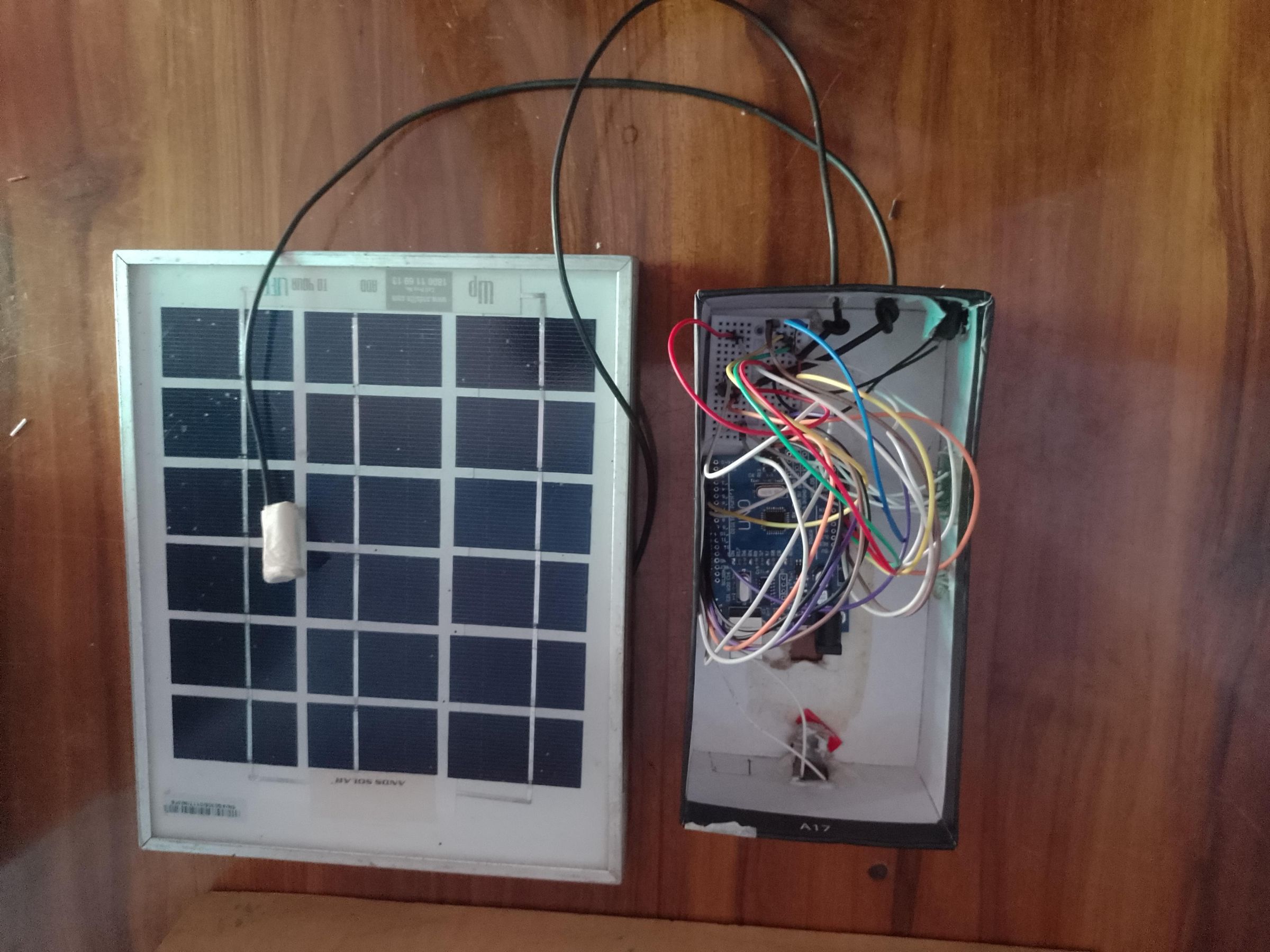
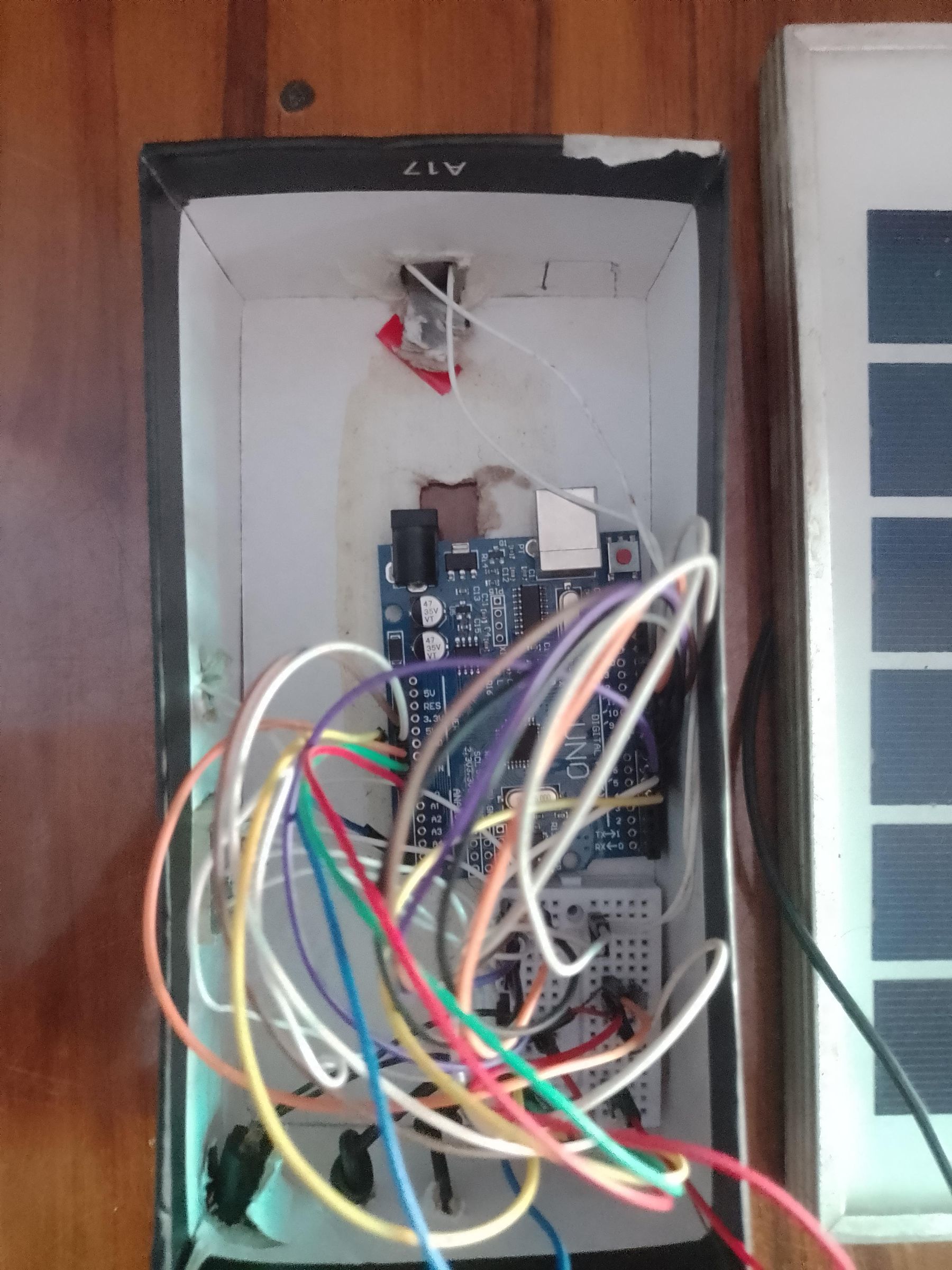
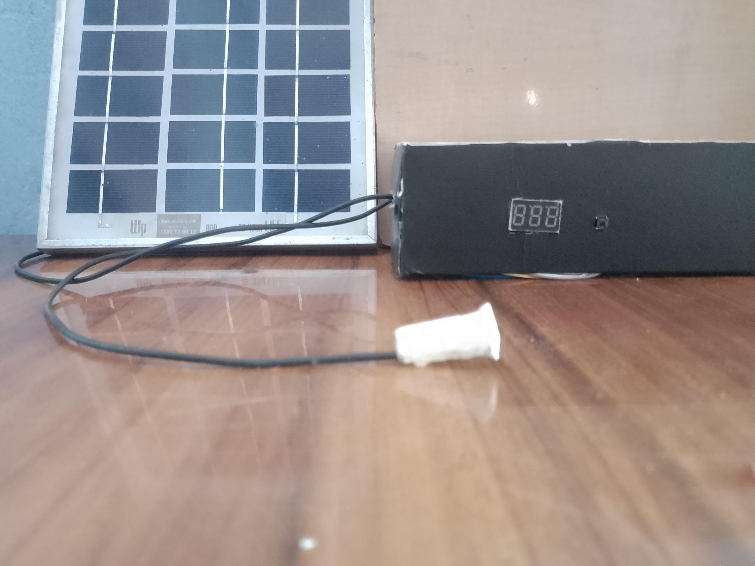
Your prototype photographs show the Arduino and breadboard mounted inside the enclosure, with the solar panel positioned beside it.2
What Makes My Project Different?
The main idea isn't simply:
"Sensor → Arduino → Buzzer"
Instead, my prototype combines several functions into one standalone warning unit:
Sensor → signal measurement → danger-level calculation → numerical indication → audible warning
It also has:
☀️ Solar-powered operation
3-digit danger intensity display
Variable audible warning
Alarm-stop button
Homemade mechanical sensor
Arduino-based decision system
Compact standalone enclosure
The homemade sensor is particularly interesting because it was constructed using a spring and metal pipe, rather than using an expensive commercial sensor.
How the System Works
The basic operation is:
☀️ SOLAR PANEL
│
▼
POWER SUPPLY
│
▼
ARDUINO UNO
│ │
│ │
▼ ▼
HOMEMADE SENSOR BUTTON
│
▼
SENSOR MEASUREMENT
│
▼
DANGER CALCULATION
│
┌────┴─────┐
▼ ▼
000–999 ALARM
DISPLAY FREQUENCY
When the sensor detects normal conditions, the display remains at a low/normal value and the alarm stays off.
When the sensor signal increases beyond the programmed threshold, the Arduino determines the danger intensity.
For example:
Display
Meaning
000–199
Normal
200–399
Low
400–599
Moderate
600–799
High
800–999
Very high
These numbers are not universal danger measurements. They are an intensity scale produced by your prototype. The thresholds should be calibrated according to whatever physical phenomenon your homemade sensor is actually measuring.
That distinction is important when presenting the project to judges.
The Homemade Sensor
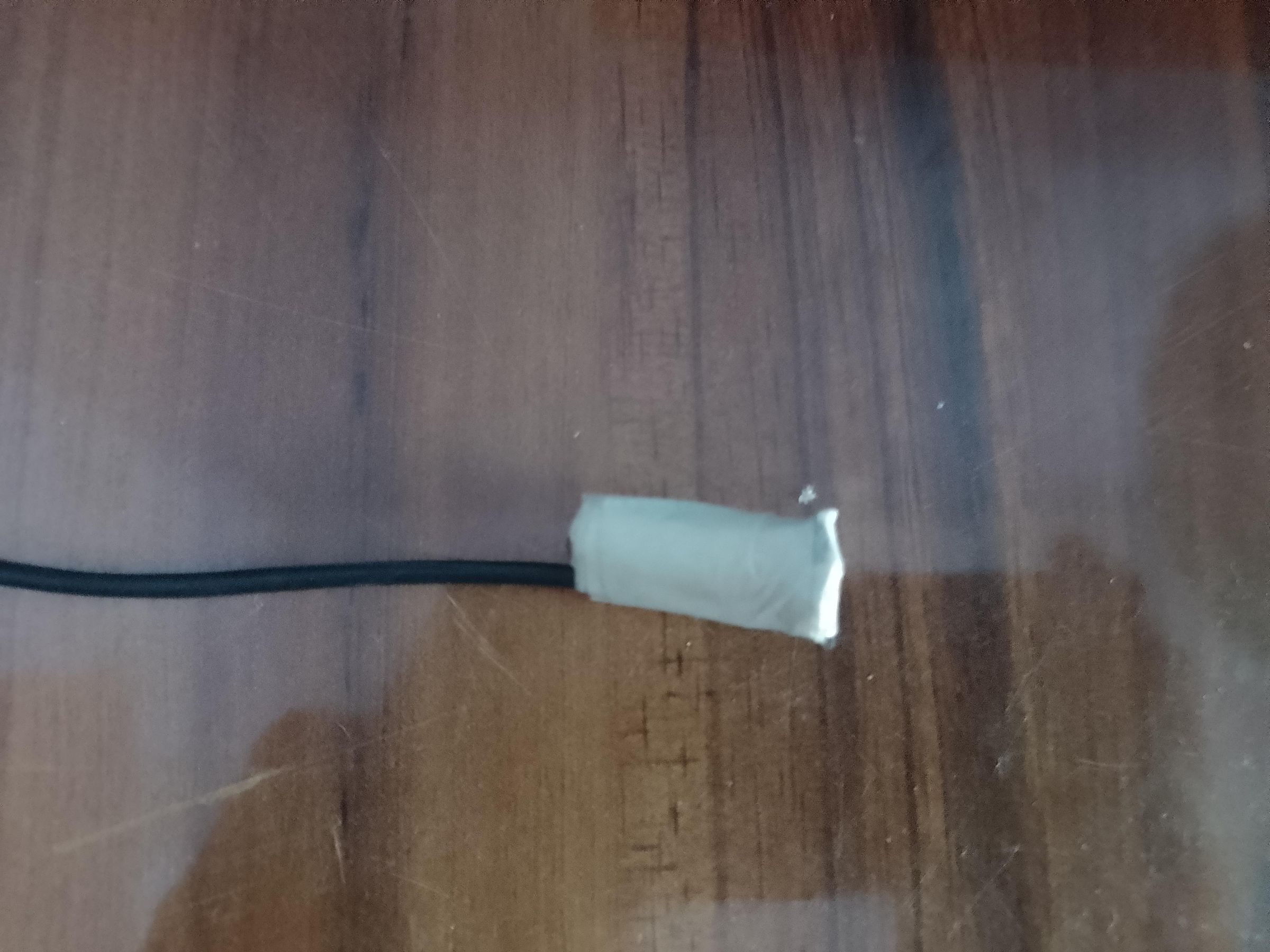
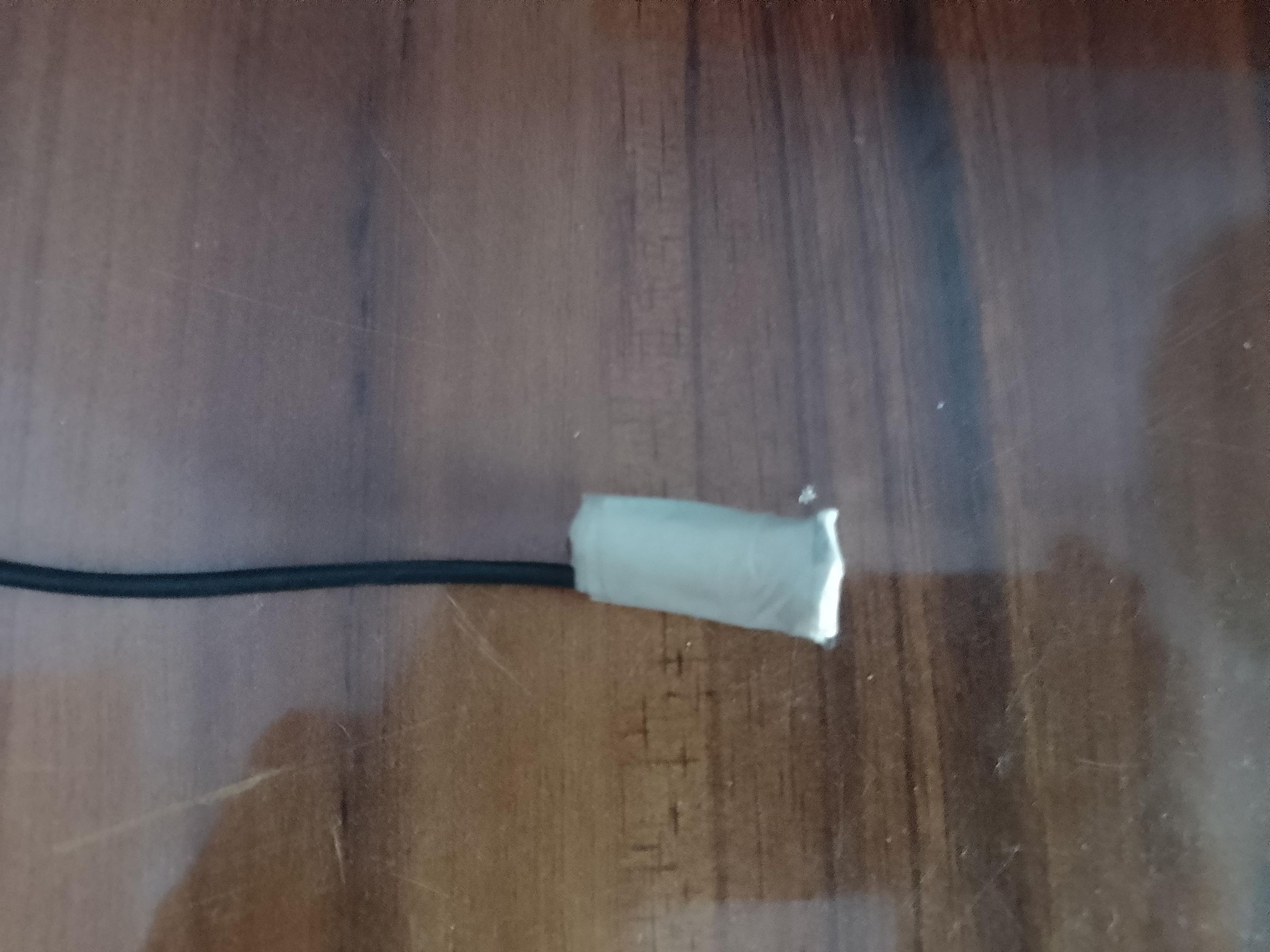
One of the most interesting parts of your prototype is the white sensor shown in your photographs.
You made it using:
A spring
A metal pipe/tube
Connecting wires
A simple insulating/support material
The spring and metal part can respond to mechanical changes such as vibration or movement, depending on how you constructed and connected it.
The important thing for the Instructables documentation is to explain exactly what physical change your sensor detects.
For example:
"I developed a simple homemade sensing element using a spring and metal pipe. When the monitored physical condition changes, the sensor produces a corresponding electrical signal. The Arduino reads this signal and converts it into an intensity value."
Don't claim that it measures something like temperature, sound, earthquake intensity, etc. unless you have actually tested and calibrated it for that quantity.
Building the Enclosure
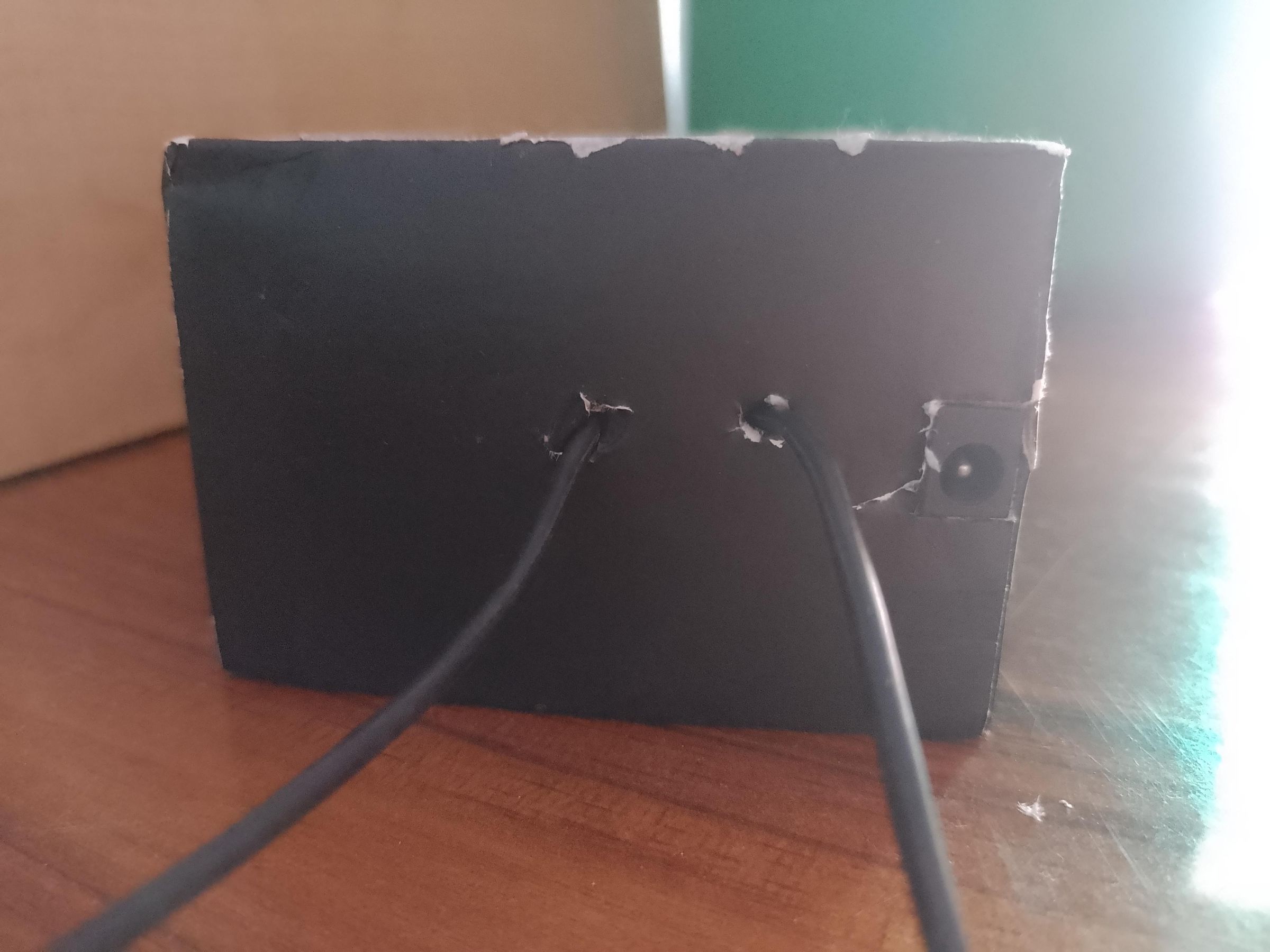
I started with a simple lightweight enclosure.
I cut openings for:
The 3-digit display
The alarm/speaker
The sensor connection
The control button
Wiring
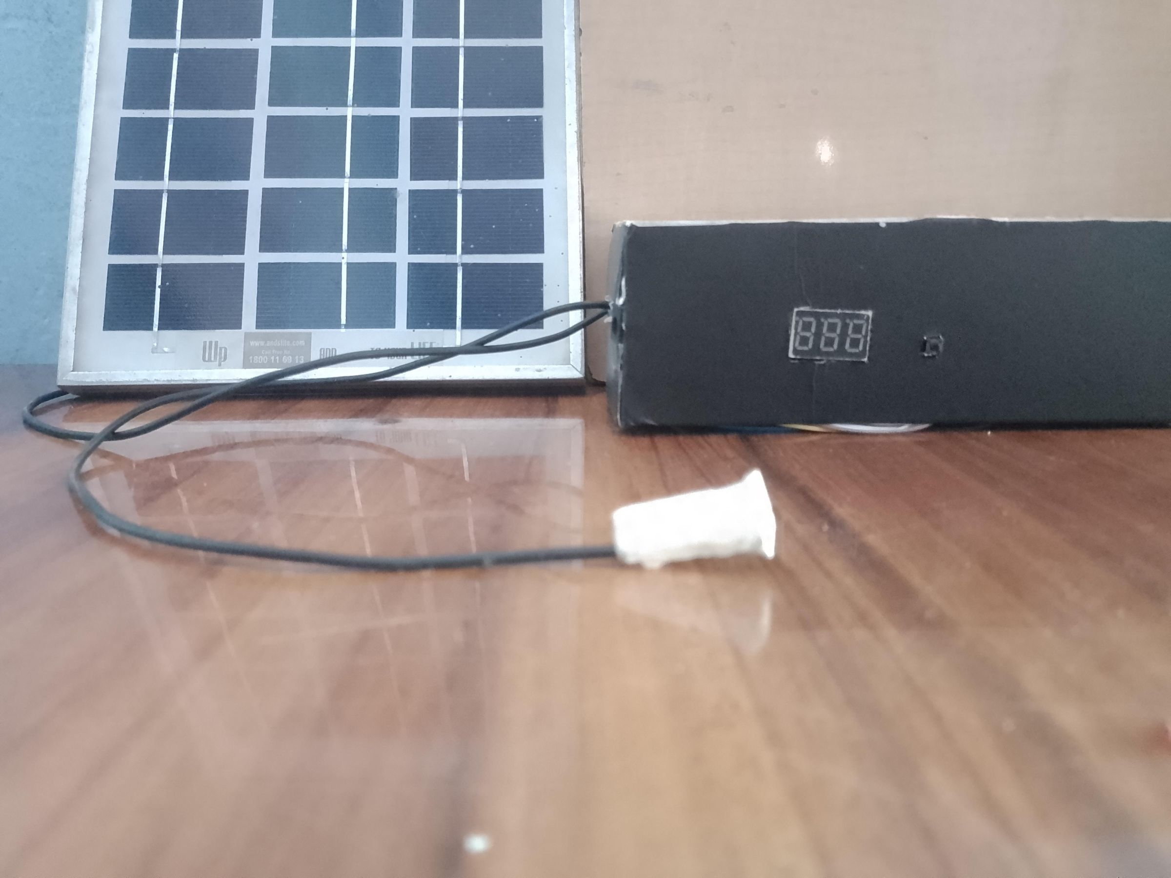
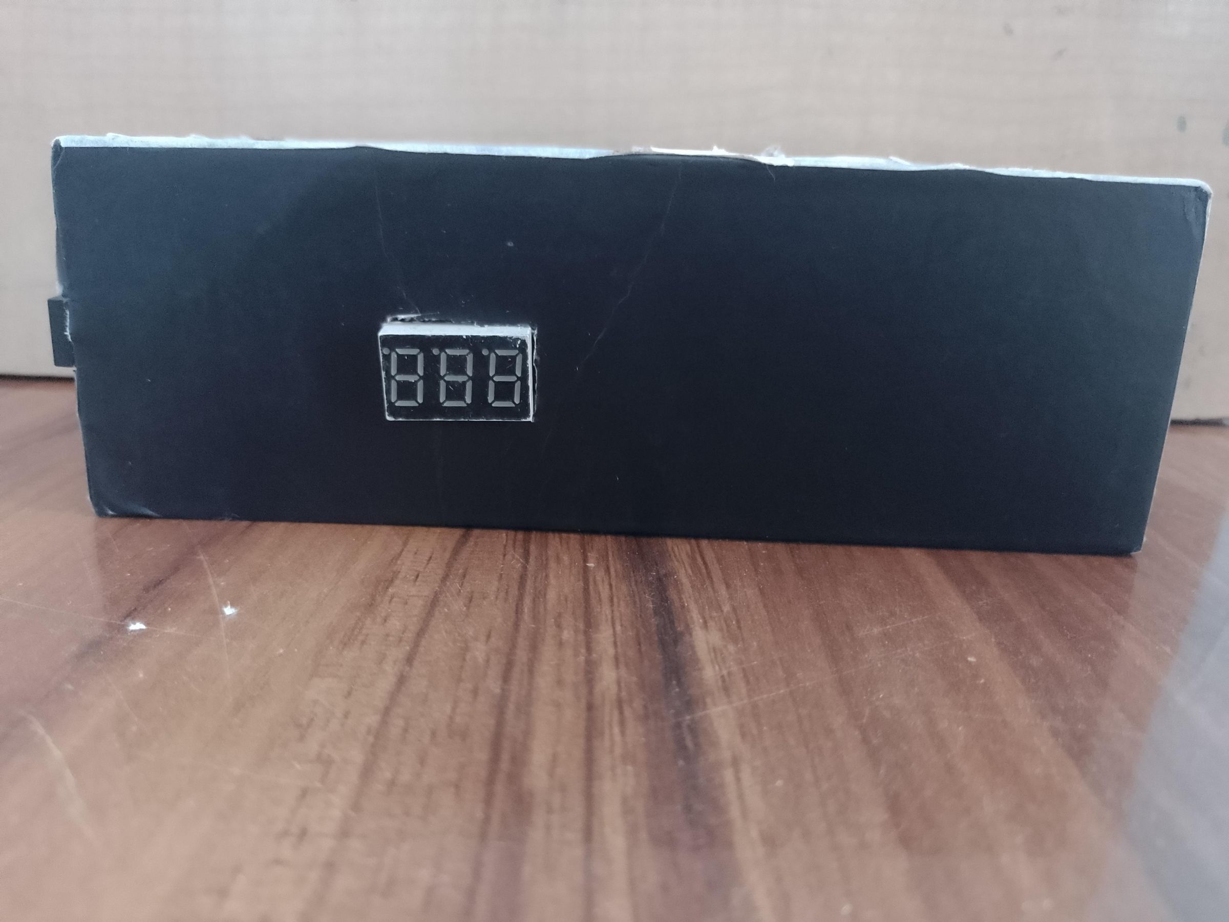
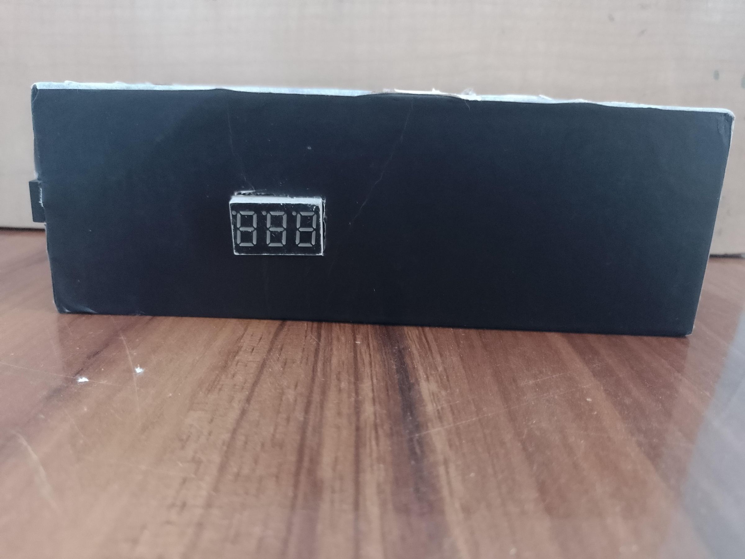
The front of the prototype contains the numerical display and alarm control.
The Arduino and breadboard are located inside the enclosure.
This keeps the electronics protected while leaving the display and controls accessible.
Installing the Display
The 3-digit 7-segment display is mounted on the front panel.
Its purpose is to provide an immediate visual indication of the calculated danger intensity.
Instead of simply displaying:
DANGER!
the device provides a numerical value such as:
327
or
784
This gives the user an indication of how strong the detected signal is according to the system's calibrated scale.
Adding the Alarm
The audible alarm is connected to an Arduino output.
Instead of using one constant sound, the program can change the alarm frequency according to the danger level.
For example:
Low danger → slower/less urgent beeping
Medium danger → faster beeping
High danger → more urgent beeping
Very high → rapid warning
Conceptually:
Danger Level ↑
│
│ █████
│ ████████
│ ███████████
│ ██████████████
└──────────────────────→ Alarm urgency
This means the user doesn't necessarily need to look at the display to realize that the situation has become more serious.
Alarm-stop Button
I placed a push button beside the alarm/display area.
Its purpose is:
Stop the audible alarm after the user has received the warning.
For example:
Danger detected
↓
Display shows intensity
↓
Alarm starts
↓
Person notices warning
↓
Button pressed
↓
Alarm stops
The danger monitoring itself should continue after the alarm is silenced.
That is an important design feature.
The button should mute the alarm, not permanently disable the detection system.
Solar Power
One of the major features of the project is that it doesn't have to depend entirely on a wall outlet.
The solar panel supplies energy to the system through the appropriate power-management circuitry.
The basic concept is:
☀️ Sunlight
↓
Solar Panel
↓
Power Regulation / Charging
↓
Arduino + Sensors + Display + Alarm
If you are using a battery, your final version should include a proper solar charge controller and suitable battery protection rather than connecting a battery directly to the panel.
This is important for safe and reliable operation.
Arduino Program Logic
The software follows this general process:
START
↓
Read sensor
↓
Filter/average reading
↓
Calculate intensity
↓
Display intensity
↓
Is intensity above danger threshold?
↓
YES
↓
Start alarm
↓
Calculate alarm frequency
↓
Check STOP button
↓
Continue monitoring
A simplified version of the logic is:
sensorValue = readSensor();
dangerLevel = calculateDanger(sensorValue);
display(dangerLevel);
if (dangerLevel >= DANGER_THRESHOLD) {
alarmOn();
}
else {
alarmOff();
}
if (stopButtonPressed) {
alarmOff();
}
For your actual Instructables article, I would include your complete working Arduino code underneath this section.
Why Use a 000–999 Scale?
A 3-digit display gives me a convenient range:
000 → minimum detected intensity
999 → maximum calibrated intensity
For example:
NORMAL
084
then:
WARNING
527
and finally:
HIGH DANGER
913
The number isn't intended to represent a universal physical unit.
It represents the calibrated intensity index generated by my prototype.
This makes the system flexible: the same basic architecture could potentially be adapted to different sensing applications after appropriate calibration.
Testing
I would recommend documenting your testing very clearly.
Make a table like this in your Instructables project:
Test
Sensor input
Display
Alarm
Normal condition
Low
000–199
OFF
Small disturbance
Medium-low
200–399
Low warning
Moderate disturbance
Medium
400–599
Warning
Strong disturbance
High
600–799
High warning
Very strong disturbance
Very high
800–999
Highest warning
Then take photographs of the display at different levels.
This will make your project much more convincing than simply showing that the LED/display turns on.
Calibration
Calibration is one of the most important parts if you want this to look like a serious engineering project.
Don't simply say:
"800 means danger."
Instead, explain how you established the levels.
For example:
Record the sensor value under normal conditions.
Take multiple readings.
Introduce controlled changes to the quantity being detected.
Record the sensor response.
Determine useful thresholds.
Program those thresholds into the Arduino.
Repeat the experiment to check consistency.
You can then create a graph:
Sensor response
│
999 │ ●
│ ●
│ ●
│ ●
│ ●
000 └────────────────────────
Increasing input
That would make your Instructables article much stronger scientifically.
Future Improvements
There are several improvements I would mention:
🔋 Better power system
Add a rechargeable battery and proper solar charging circuit.
📡 Wireless notification
A future version could send an alert to a remote device.
📈 Data logging
Store sensor readings so that the system can show how the danger level changed over time.
🌡️ Multiple sensors
Instead of relying on one sensing element, combine several types of sensors.
🧠 Intelligent detection
A future version could use pattern recognition to distinguish between normal environmental changes and actual danger patterns.
🖥️ Better display
A larger display could show:
LEVEL: 782
STATUS: HIGH
What I Learned
This project helped me understand several engineering concepts:
Arduino programming
Sensor interfacing
Analog signal measurement
Threshold detection
Numerical display control
Audible warning systems
Solar-powered electronics
Basic signal calibration
Prototype enclosure design
Hardware/software integration
Most importantly, I learned that a useful electronic system isn't just about connecting components—it requires measurement, decision-making, feedback and user interaction.
Conclusion
This project demonstrates a compact approach to creating a solar-powered danger monitoring and warning system.
The homemade spring-and-metal sensor provides the sensing element, while the Arduino processes the signal and determines an intensity index.
The 3-digit display provides a visual indication, while the variable audible alarm provides an immediate warning.
The solar power system makes the concept suitable for situations where conventional electrical power may not be readily available.
My next goal is to improve the sensor calibration, power management, enclosure, and detection algorithm so that the prototype can become a more reliable real-world monitoring device.
IMAGES