Sony PVM Mini Cute! Arduino and Laptop Powered Arcade Cabinet With Built in Speakers!
1513 Views, 14 Favorites, 0 Comments
Sony PVM Mini Cute! Arduino and Laptop Powered Arcade Cabinet With Built in Speakers!


For a school project, i made a full sized arcade cabinet meant to be used with Arduino Uno powered controllers, a 14 inch sony PVM, a laptop and looks inspired by the capcom mini cute.
with this idea in mind i used the facilities that were available at my school(Lasercutter, Wall saw etc ,inkjet sticker printer) and various home tools to get the job done!
disclaimer everything i made is for personal and for school use only, so i can't give the files for the decals, but the other files have all the measurments to D.I.Y it!
Supplies
What do you need to build this cabinet?
links will be listed below (they will be the links to the Dutch websites, but you can find similar items from your own local stores!)
Electrical components:
- Sony PVM 14 inch monitor (this one is quite tricky to get nowadays, but mine is the 1454QM model, you don't need the same necessarily as long as it's 14 inches and has roughly the same dimensions( Height: 33.5 CM Width: 34.5 CM Depth: 41.5 CM) it also needs white and red RCA ports, because we're going to be using a AV to HDMI converter)
- AV to HDMI converter
- 2x Arduino UNO's (so we can have it as 2 separate controllers instead of 1 big one, this is so you can play multiplayer games seamlessly)
- Laptop or small computer that can run steam, has audio jack, hdmi and 2 usb ports
- 16x Sanwa 24 MM buttons (14 face buttons and 2 extra on the front, you can do separate colours like i did or use a single colour)
- 2x Sanwa JLF-TP-8YT Arcade sticks
- 16m of wire (i got 2 colours, blue and red. mostly so i could keep track of ground and power cables.
- plenty of jumper wires ( i used about 24, but get some extra so you can mess up )
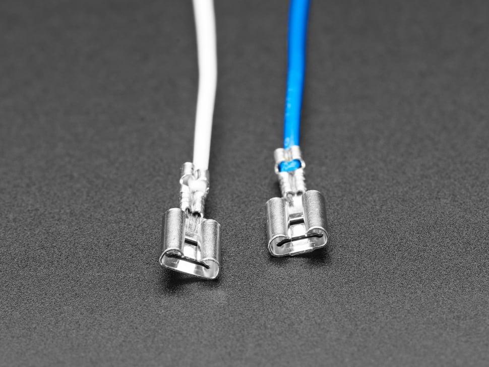
- 32x quick spade Connectors 2,8mm (.110 inch) ( every button needs 2 of these )
- 2x 3 inch 5 watt and 4Ω speakers
- 2x 3 inch matching speaker covers
- Universal MOSFET speaker amplifier 12 volt 22 watts ( this one has plenty of watts if you want to wire more speakers or even a sub )
- IEC connector with rocker switch and 15a Fuse
- BrennenStuhl EL 6-FACH MS-LG power socket plug
- 12volt 2A power supply
Woodwork:
i got these at my school so local sizes may vary
- 2x 305x122 CM of 9MM MDF ( i used this specific thickness because this is the maximum the laser cutter at school could take, the laser cutter was also a maximum size of 160 by 100 CM's so i cut the big 305x122 in two pieces of 150x122. its all double layered so you will laser cut 2 of the same templates and glue all of the pieces together)
- 305x122 CM of 18MM MDF (these will be cut either by yourself into pieces or by your local hardware store that has a wall saw)( these cutting plans will be linked )
Perspex Plexiglass:
50x50 3mm panel for laser cutting ( includes the acrylic panel for the on top of the arcade controllers)
33cm x 34cm smoked panel 5mm thickness (for shielding the tv screen of UV light and also making the colours pop!)
Hardware:
- M4 T20 screws 35mm (these are all the construction screws for the big panels)
- M4 T20 screws 16mm (smaller applications like the arcade button panel)
- 8 xM4 Alan bolts with nuts
- 6 Wheels 35 mm with brakes( so the cabinet wont shake around)
- 4 hinges
- 1 cabinet Arcade lock
- 2 glass hinges
- pcb standoffs for the Arduino UNO
- some M2 nuts and bolts approximately 20 mm long (i had these laying around at home in a box, so i don't know exactly which ones i used)
Tools:
- Wood router with depth bits (i used this one a lot in this project, mainly due to it being really useful in setting the hinges and arcade sticks in)
- wood glue
- big wood clamps
- drills and drill bits matching the size of your bolts and screws
- a hand drill for driving in screws( please save your hands by using this, it takes way less time and less wrist pain)
- Laser cutter (i used one at school that was sized for 160x100 cm's)
- Wall saw (or anything that can cut large panels of wood perfectly straight and aligned)
links:
( some items are unlinked due to them being available from any website, so you can pick and choose whichever you want,make sure you run by the list of things you need and things i linked to know for sure you got everything)
sony-monitor_pvm-2054qm.pdf (awi.de) not a link to buy one just general info about the monitor, i picked this monitor because of its classic CRT look but also still having good resolution
Arduino Uno Rev3 — Arduino Official Store
ArcadeWinkel | Versterker universeel (mosfet), 12 volt - Geluid
ArcadeWinkel | Sanwa OBSF-24 pushbutton, lichtblauw - Drukknoppen
ArcadeWinkel | Sanwa OBSF-24 pushbutton, rood - Drukknoppen
ArcadeWinkel | Sanwa OBSF-24 pushbutton, wit - Drukknoppen
ArcadeWinkel | Kabel, blauw (per meter) - Kabels & connectoren
ArcadeWinkel | Kabel, rood (per meter) - Kabels & connectoren
ArcadeWinkel | Kabelschoen 2,8mm (.110 inch) - Kabels & connectoren
ArcadeWinkel | Versterker universeel (mosfet), 12 volt - Geluid
ArcadeWinkel | Speaker rond 3inch - Geluid
ArcadeWinkel | Speaker grill zwart klein 3inch - Geluid
ArcadeWinkel | Power switch gezekerd - Switches & schakelaars ( you need to add a 15 A fuse for certain appliances, in my case a laptop)
EL 6-FACH MS-LG: Stekkerdoos ECO, met schakelaar, lichtgrijs bei reichelt elektronik
Spaanplaatschroef 4,0x35mm - RVS 304 (A2) - Torx 20 (100 stuks) - €4.89 | MeubelbeslagXXL
Spaanplaatschroeven 4,0 x 16 Torx bestellen | Ecotools.nl
Concept!


my personal first step was to get to drafting the idea! can't have any building plans without a concept.
i measured the height i needed which at first i wrote down as 160, but i eventually shrunk that down by 5 cm's so it would sit at a more comfortable standing height.
in the top left i measured the sizes of the TV itself, which as described before is:
Height: 33.5 CM Width: 34.5 CM Depth: 41.5 CM
i also ended up going for a flat back door instead for ease of use
and i scrapped the extra front door since it would have no use for this project, i may end up redoing it for another time though!
next i mocked it up in 3D to get a better idea of how it should look in space
after that i thought out what it should be constructed like ( disclaimer, minor things change in the end compared to the sketches to keep the build relatively simple )
basically it is a cabinet inside a cabinet, the main cabinet consists of a top and bottom panel.
its 38 cm's wide and 42 cm's deep and 95.6 cm's high in total.
while the bigger outside panels go up to 145 in height and 50 cm's in depth.
this is to create some breathing room inside for cables and other things.
also 38 + (2x1.8 cm for the side panels) adds up to 41.6 which is the width of the front door.
Lasercutting


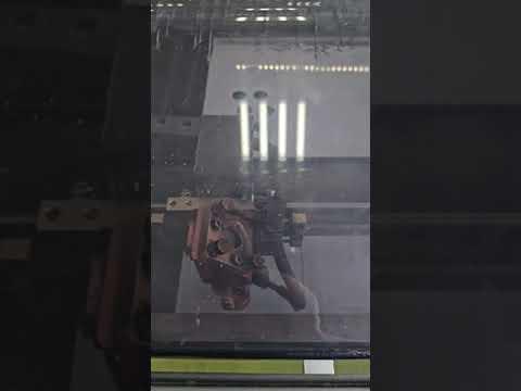
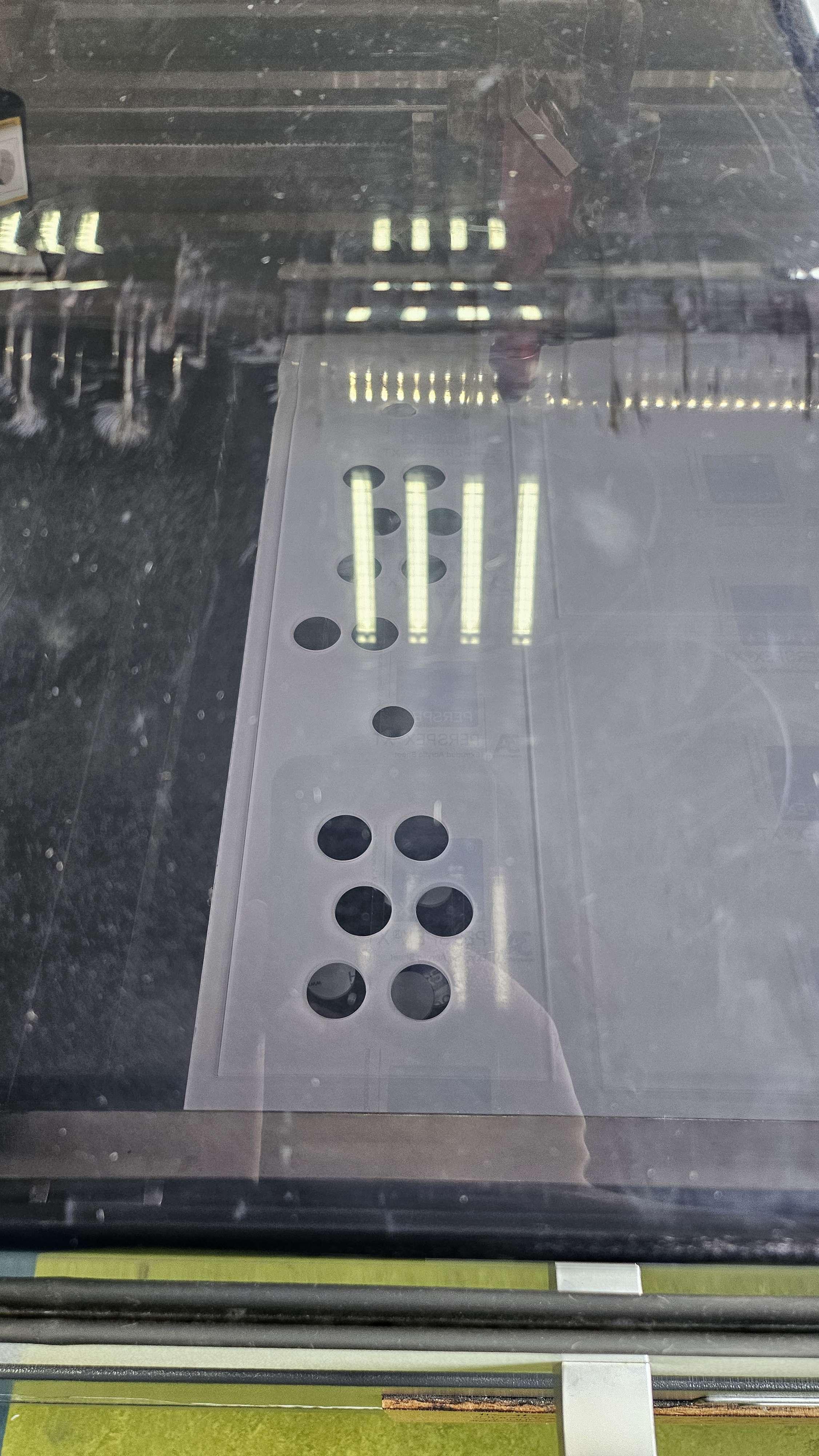
My second step was laser cutting the control panel for the arcade stick, the big side panels, and the front panels this part is pretty straight forward, just put these into your preferred laser cutting software and cut away! these were made and sized by me, the only thing is that i had to scale these up to 1000% in the software we used, while the illustrator sizes were true to size. so if anyone knows a fix let me know, but in the end scaling up worked.
some pointers:
the reason for those notches being put in the wooden control panel and not in the acrylic/plexiglass panel, is because the buttons i used are Sanwa snap in buttons, they go up to about 5 mm thickness and a minimum of 3 mm.
so i thought i should use the acrylic to my advantage and make the buttons snap in them, while at the same time the notches were designed so they could slide past the wood and not be forced in. without the notches the buttons "snap in" mechanism wouldn't work and they also served for some more sturdiness in the buttons since now they couldn't spin in the housing!
Making the Controllers Work!


In this step I'll be going over how i made the controllers work.
the reason i started doing this after i cut my panels is so i could get a feel for the controllers, while having a bunch of loose buttons is fun it wasn't ideal for testing the layout i had in mind.
so without further ado!
first i used a wood router to route out the shape of arcade stick plate, this was done in about 2-3 mm's of depth
this is so the plate could fit flush on the inside of the stick. this is done to eliminate any movement when using the stick in a rough matter.
you could skip this, but i would advise against it since you can pull your stick loose if you dont.
Wiring:
next i had to figure out wiring, which is illustrated in one of the pictures i added to this step.
the wiring is fairly simple, one big common ground wire coming from the joystick into the ground and splitting out to the buttons. this is done by stripping a jumper cable and wiring it to the cable coming from the joystick and the cable going to the first input button and then the rest is daisy-chained to the other buttons. the jumper cable goes into the GND input on the Arduino. (every wire that goes to a button has one of those quick connectors on it, i soldered and insulated all of mine on but you can also buy pre crimped or soldered versions )
then next every single wire that goes to an input is combined with a jumper wire,
so strip both ends, twist them together ( i use pliers in the middle and then twist them in clock wise and counterclockwise directions), solder the connection and then insulate with some shrink tube!
in image 9 you can see all of the digital inputs going to a jumper wire.
Extra wiring:
at this time i also wired, the speakers.
I used this video on how to wire speakers here:
How to Wire Audio for Your Arcade (youtube.com)
i also wired an IEC power connector: here's the video i followed as instructions on how to do it (warning! this is really high voltage work and if done wrong could potentially be deadly, so only do this if you either know an electrician or are one):Wire an IEC 320 C14 Power Socket with LED Rocker Switch - Arcade Build Series (youtube.com)
Coding:
To get the inputs to actually read i have a few scripts. one I made for testing purposes and a really good working script made by srodriguez1850 that i made some changes to to make it work for my goal.
everything is based on the Unojoy library, here's a link to that: AlanChatham/UnoJoy: UnoJoy! allows you to easily turn an Arduino Uno (or Mega or Leonardo) into a PS3-compatible USB game controller (github.com)
in short, you upload the testing code to your Arduino so you can test the button input in the serial monitor. it only shows up when you actuate it and when you release the input, it stops printing lines. i did this so you don't have to necessarily use the processing sketch that unojoy uses.
if everything works you should upload the final_arcade_stick code to your Arduino and put it into DFU mode by touching the 2 pins in the 10th picture with one of the jumper wires metal end. you do this so you can flash your Arduino as a USB input device. more on that over on the Unojoy link.
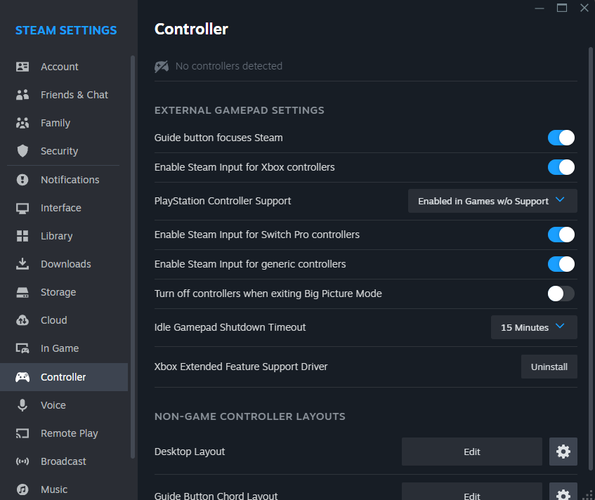
once you've flashed it you go over to steam and map your input to the controller
it will look something like picture 11 but then the Unojoy controller will show up
in picture 12 it describes how you should map it to make it work with most fighting or arcade style games.
if you did everything right it will work just like the video i attached!
hardware:
for keeping the sticks and the acrylic panel together you can use small M2 bolts and nuts.
you can route in a few mm's to get them to sit flush for the acrylic panel.
i also drilled some holes in the panel to attach it to the MDF panel!
Woodwork and Finishing Assembly


For this step i have some descriptions for getting the panels cut out and assembling them for the cabinet itself.
but first! before you forget, you should glue all the 9 mm panels together, the only ones you shouldn't glue together are the top panel of the control panel and the front panel of the control panel. this is due to there not being enough space inside of it. all the others should be glued!
the other panels are described with the Opti cutter document. there you can see how much you need and how to efficiently cut it in around 12 cuts.
before assembling i primed all the MDF panels that are visible on the outside, when primed and filled you line up all the front panels like a puzzle piece and use screws on the front to assemble the frontside panels on.
screws on all corners is also important for stability.
when done with the front door get all the panels for the inside cabinet and mount them as seen in picture 4,
i use corner brackets on all corners on the top plank and bottom plank. and then screw in the shelves from the sides.
this makes the inside cabinet super stable. next when done you glue on the side panels and secure them with more screws.
next fill up the screw holes with wood filler and sand clean!
then glue on the top panel ( this panel needs a 43 degree angle cut on both sides so it lines up neatly on the top )
there is an extra triple sandwiched piece of MDF on the bottom of the front door this is 3 layers of 18 mm in 41.6 x 25 CM's and then cut at a 33 degree angle! i made a .AI document showing what it should look like.
this one needs to be screwed in from the inside of the front door.
Control panel
- first, you should get the back panel with the square and clamp it to the front door. then you drill 8 M4 sized holes in the panel and the door and put the 8 xM4 Alan bolts with nuts through the panel with the nuts threading in from the back of the front door(shown in the pictures) this is done so you can take the control panel off when you need to switch out buttons or tinker on your Arduino.
the control panel should be started from the bottom panel, then glue and screw on the small side panels with the 35mm screws. then the front and back panel glued from the bottoms and screwed in from the sides.
lastly align the top panel and use the shorter 16mm m4 T20 screws to not permanently attach the top panel( we don't use glue here so we can get inside and change up electronics )
before moving on to painting there are triangle shaped supports that go under the control panel, there is a matching panel in the cutting plans that's called "support panel for triangle" this one needs to be cut on 45 degree angles so you can perfectly place it under the control panel (as seen in the pictures) just glue on the sides and then screw it in from the inside of the door!
last things are: routing in the hinges for front and back ( this can be done by your own placements )
routing in the glass hinges on the inside of the door panel for the glass.
putting the 6 wheels on the bottom of the cabinet.
mounting the speakers and amplifier.( not final mount because of painting)
and lastly routing in the IEC panel and putting it in
then finally we can go on to painting! this step just is also just up to your free will but i used petrol coloured paint by rust oleum!
when finally dry after a few coats add your decals and insert all your tech!
Tournaments

then finally,
gather up friends and host a tournament with your new arcade cabinet!
this was quite a big project and i had around 7 weeks for the complete build including making the building plans etc. but i had lots of fun learning new things like lasercutting and using a big wall saw to cut wood. i will definitely try and make more projects with Arduino too! most of these things were done for the first time for me but now knowing i love doing projects like this, it's definitely not the last time!
thanks for checking out my instructable and till the next one!