RC CamQuipped Tank


Building a simple cardboard Fire-nation RC tank with live video feed. Our motivation for building this tank is the simplicity and the challenge. (Also that I love avatar😁). The fire nation has some of the greatest character development in history (Zuko turning from an Aang chassieur to a peace maker), and using those great machines for peace.
Supplies

Materials
- Cardboard boxes
- Type 280 DC motors
- L298N motor driver
- MT3608 DC-DC Boost converter
- 1KiloOhm resistor
- Any colour LED
- Female to Female connectors
- Male to female connectors
- (Optional) Ethernet cable- To be stripped
- ESP32 Cam
- Battery(Preferable Li-ion)
Tools
- Craft knife
- Ruler
- (Optional) Scissors
- Masking tape or Hot Glue
- FTDI Adaptor
Cutting Out the Frame

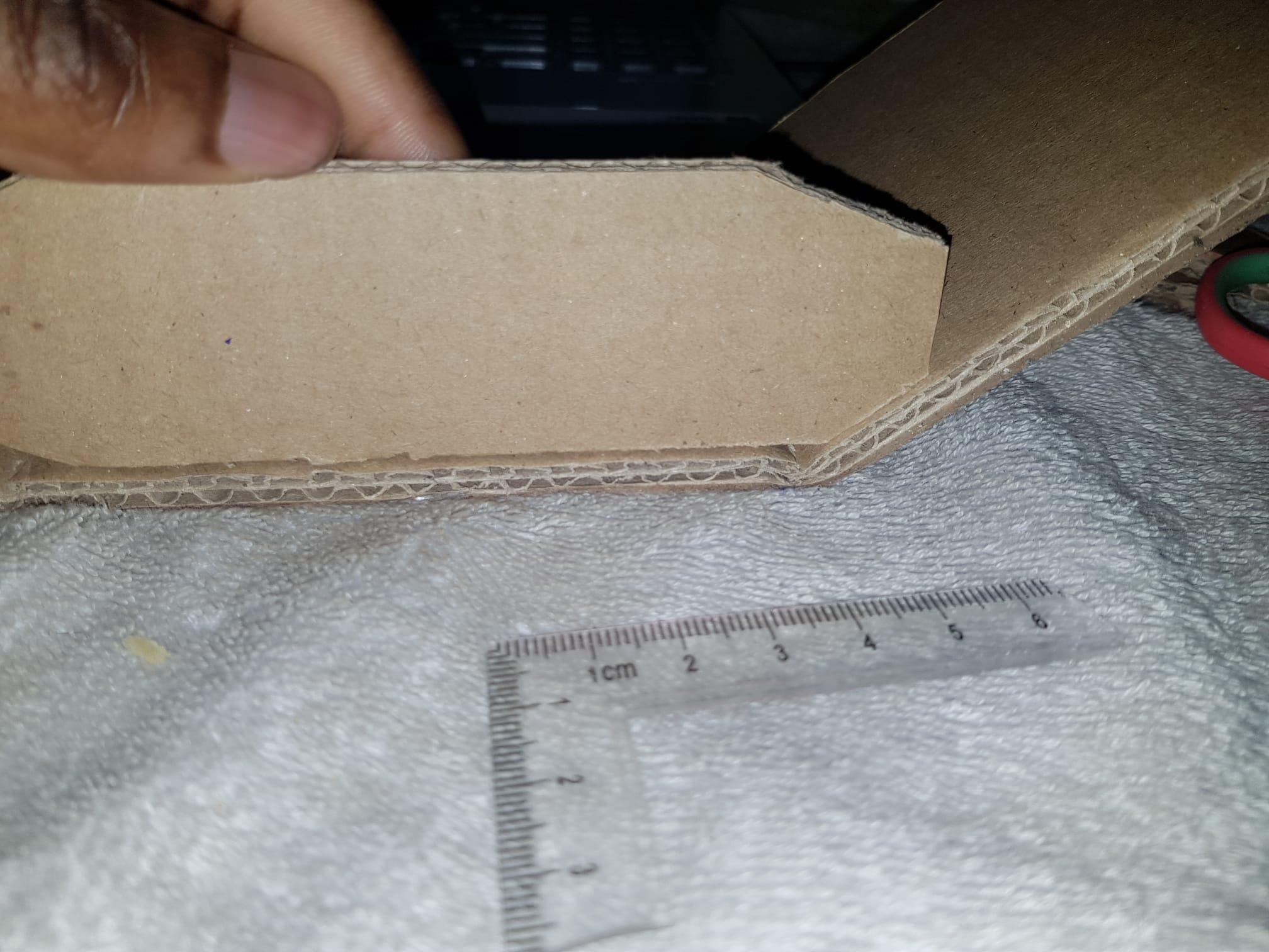
Cut out the cardboard parts according to the dimensions in the CAD images above. You can use a pen to mark the dimensions on a sheet and start cutting from there. In the side profile, the angled construction (broken) lines represent where you should cut. While in the bottom profile, they represent where you should fold the cardboard. You can use any hard edged object to make the folds(Note that the dimensions are not exact, so you have some wiggle room for adjustment).
Ensure that your bottom profile's height is at least 12cm wide to accommodate two 280 motors.
Afterwards, you can assemble the pieces with tape or hot glue like in the step below
Assemble Frame


Here We need to glue or tape the peices together to make the chassis of the tank.
The shorter angled edge on the side profile should be oriented on the bottom.
The bottom profile should neatly fold around the two side profiles.
Pierce two holes in the side profiles using the 280 motors.
Connections


Here I use a mini breadboard, because I am yet to get soldering flux.
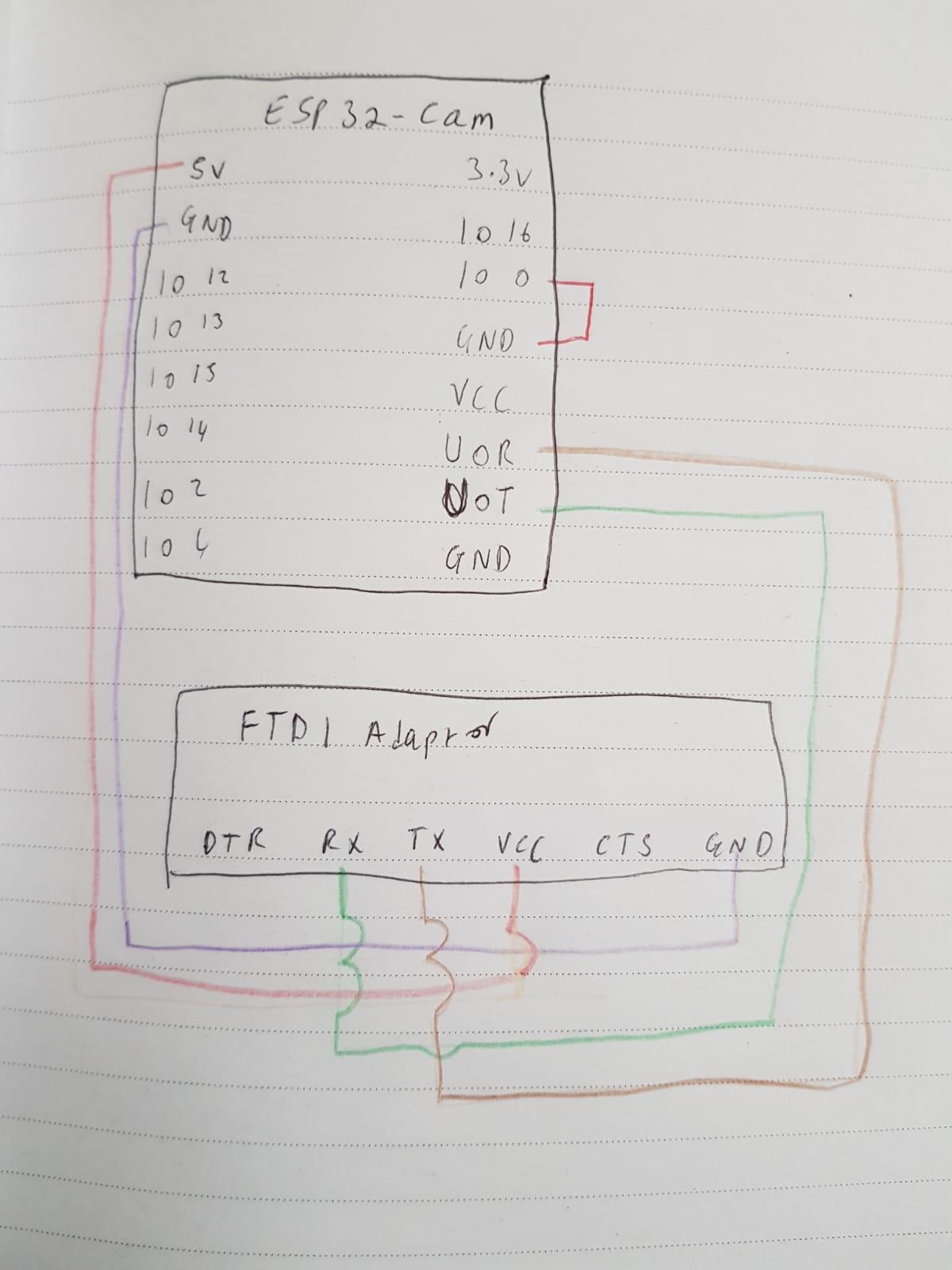
ESP32-CAM → FTDI Adaptor (for programming)
- U0T (TX) → FTDI RX
- U0R (RX) → FTDI TX
- GND → FTDI GND
- 5V → FTDI 5V
- IO0 → GND (Only while uploading code — acts as flash mode switch)
After uploading the code, you can remove the wire you used to connect IO0 and GND.
Here I used iron wire to connect the driver. If you have more connectors with at least one male head, you can strip the other head and knot it to the board, or solder. Alternatively you could use ethernet cable wires which are similar to the iron wire I'm using here.
ESP32-CAM → L298N Motor Driver
- 3.7V (from Battery) → L298N 3.7V
- GND → L298N GND
- GPIO 12 → IN1 (Left Motor Direction)
- GPIO 13 → IN2
- GPIO 14 → IN3 (Right Motor Direction)
- GPIO 15 → IN4
Here I stripped the female head of the connectors and knotted them to the terminals of the DC motors. I then connected the male part to the breadboard
Motors
- Connect your Type 280 DC motors to the OUT1/OUT2 and OUT3/OUT4 terminals on the L298N.
ATTENTION: Do NOT connect the Boost Converter to the ESP32 cam yet. use a multi meter, an oscilloscope or some other viable tool to adjust the output to 5v. Then you can connect the ESP32 Cam.
ESP32-CAM Power
- Battery (Li-ion) → MT3608 Boost Converter
- MT3608 Output 5V → ESP32-CAM 5V pin
- MT3608 GND → ESP32-CAM GND
LED and Resistor
- 1K Resistor connected in series with the LED
- 5v pin → Anode of LED
- Cathode of LED → GND
How to Use Code
Download the provided Arduino sketch and open it in the Arduino IDE. Make sure you have the correct board and port selected under Tools > Board and Tools > Port.
To use the code:
- Connect your components according to the wiring diagram in the previous step.
- Upload the code to your Arduino by clicking the Upload button (right arrow icon).
- Open the Serial Monitor (Ctrl + Shift + M) or Serial Plotter (Ctrl + Shift + L) to view output data or debug information.
- If needed, adjust values in the code (like sensor thresholds, delays, or pin numbers) to fit your setup.
That’s it — your project should now be alive with the uploaded code! But we're not done yet.
Work in Progress
This instructable is a work in progress. Please bear with me. I ran into some problems uploading code to the ESP32 Cam. The camera is not detected, no matter what I do. If you have a fix for this kind of problem, your input is welcome and appreciated. In the meantime, I'll be off on another more exciting project for you guys.