Spatial Desktop Clock

"Arrow of time"
Perception of time is really an amazing and fascinating topic. Often we see analog clocks and get a feeling "Are we stuck in a loop going round and round"?, though in reality time is flowing continuously.
Inspired from this, I thought of making a simple desktop clock to visualize the flow of time in spatial dimensions from analog round dial clock.
From front view we can witness an analog round dial clock, from side view a linear clock, isometric view would visual spiral flow in 3D.
Supplies

Materials:
- Acrylic Transparent Slides x 13 - 5mm Thickness
- Acrylic Colored Slide x 1 - 5mm Thickness
- RGB LED strip WS2812B - 144 LED/meter - 12 LED length
- XIAO ESP32-C3 module x1
- DS3231 RTC Module x1 (Optional)
- 30 gauge wire - 2 meter
- M3 x 5mm x4
- M3 Brass Inserts x4
- USB-C cable
- 3D printed parts:
- Holder x1
- Lid x1
Tools:
- Drilling Machine with M5 drill bit
- Knife
- Paper Tape
- Soldering Iron
- Wire Cutter
- Screw Driver
- Marker Pen
Software:
- Arduino IDE
Inspiration

TIME
Acrylic Parts -1

Laser cut acrylic parts, 5mm thickness
Transparent slides x 13
Colored slide x 1 (Optional) - Used for marking the holes for drill
Acrylic Parts - 2

- Align the bottom of the colored slide to the transparent slide
- Mark all the slides as per the colored slide through holes
- Starting with the first drill hole overlapping
- Mark with a marker pen from colored to transparent slide
- Similarly mark consecutive hole to each transparent slide
- Now, we have each transparent slide with one mark which is unique to each other
Acrylic Parts - 3


- With drilling machine, loaded with M5 drill bit
- Drill a blind hole up to 4mm approx. on transparent slide
- Similar procedure is followed for all the 12 transparent slides
3D Printed Parts

- 1 set of each base and lid is FDM 3D printed:
- Color: Black or any dark color so that light leakage is minimized between inter slide
- Infill: >40%
- Quality: Standard
- Brass Inserts is installed with a soldering Iron press at 4 places to fasten the lid with the base
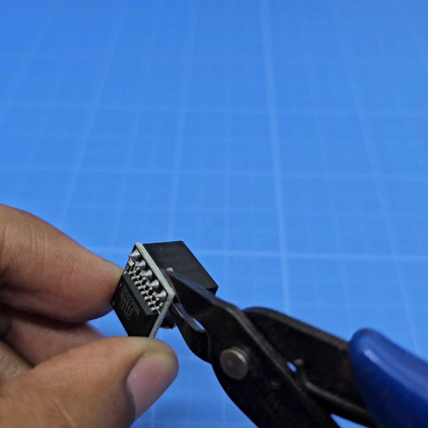
DS3231 RTC Modification


- The height of the RTC is a bit higher than the base enclosure
- A modification is done to reduce the height
- Battery which is by default on top of the PCB is de-soldered and placed next to the PCB side by side and soldered
- Important Note:
- De- solder and Re-Solder the battery pins one at time without shorting the battery terminals with metal soldering iron
- Make sure battery polarity is same before and after the soldering, marking the terminals with marker and taking photographs were few methods I followed to double confirm
Electronics


- Solder the wires as per the wiring diagram
- Power the ESP32 module with USB and test for WS2812B and RTC
- Device is powered by external USB - C cable
Electronics Assembly


- Dedicated slots are provided on the 3D model to house the ESP32 module and LED per slide
- Module is installed in the slot and then LED strip as per the below attached Image
- ESP32-C3 module comes with an external U.FL Flexible PCB antenna with adhesive backed
- RF connector is installed and antenna is stuck on the base surface as shown in image
- Double check the wiring once visually and test for short circuit between 5V and GND
- Check for any polarity inversion between the wiring of LED strip and RTC module
- Close the Base part with 3D printed lid and fasten with M3 bolts
Functional Tests

- Connect ESP32-C3 to PC and open Arduino IDE
- Install ESP32 Boards from Tools>>Boards Manager >>ESP32
- Select Tools>>Boards>>ESP32 Arduino >>XIAO_ESP32C3
- Select the COM port
Libraries Required:
RTC connection test:
- Open File>>Examples>>Wire>>WireScan
- Upload the code to list a I2C device connection displayed in serial monitor with Address which makes sure the RTC connection to ESP32 is success
RGB LED connection test:
- Similarly run a test code for RGB LEDs with FASTLED
- Open File>>Examples>>FASTLED>>DemoReel100
- Change parameters in the code:
- DATA_PIN 4
- LED_TYPE WS2812B
- NUM_LEDS 12
- Upload the code to check if all LEDs are lighting up
Main Code

- Upload the main code "Spatial_Clock_IZ.ino"
- If DS3231 is used, time has to be set for first time
- Firstly upload the code by uncommenting the update time line
- rtc.adjust(DateTime(F(__DATE__), F(__TIME__)));
- Then comment the same line and re-upload the code to set the time
Downloads
Install Slides


- Install the transparent slides,
- First one is fully transparent for visual window
- From second, slides are inserted in slots of the base in sequence with drill hole - counter clockwise from first hole
Working Description


- 12 hour clock format
- Hour is represented by 2 colors
- PM: Orange
- AM: White
- Minutes is represented by Green color
- Seconds is represented by blinking the Green color in minutes slide (Blink rate ON=1 second; OFF 1 second)
- Minutes is incremented every 5 minutes from one slide to another similar to analog minute clock hand (60 minutes / 12 = 5)
- For every 1-hour there would be a blue color sweep across 12 slides to indicate the hour transition
Perspective

From front view we can witness an analog round dial clock, from side view a linear clock, isometric view would make a sine wave in 3D.
In Action

ESP32-C3 has Wireless functionality, It can be used for NTP (Network Time Protocol) time sync, notifications, timer and other custom applications etc.,
Wrapping it up!
Hope you enjoyed the project ,
Thank you and happy making! 🚀
Instagram: @ideazero_
P.S
