Splash! Water Droplet Photography
by alexpikkert in Circuits > Arduino
16971 Views, 116 Favorites, 0 Comments
Splash! Water Droplet Photography
.jpg)
.jpg)
.JPG)
I have been shooting water drops for a while now.... since 2017. I still remember how excited I was when I got water drops bounce from the surface with my first setup I made with Littlebits... With these setups (Mark I and Mark II) I became inspired to give it a go and finally I succeeded in making a few drops collide in mid air.... The timer settings were controlled with analog potmeters and a large amount of luck was needed to let the drops really collide..The water valve was a not very accurate self-made (Littlebits) servo construction, quenching a little tube under a water bottle to block and release the water. There are many very talented water drop photographers out there, much of their works puts mine to shame...
After this first adventure I stopped for a while and recently I started searching the internet to find a better water droplet system. First I decided to use high quality components for the valve and the siphon and bought both parts as spare parts from Cognisys. Then the controller needed to be made. I made a few other projects with the little Arduino computer so it was an easy decision to build my own controller with Arduino. Now I could search more detailed and I found a great controller to start my project on the photobuilds website in the UK, a site dedicated to making and modifying stuff that can be used for photography:
I really want to thank the author(s) very much for this information, I would never have come so far in making my own controller ! It worked after the first assembly, but to make it even better I made some changes in the original design, see step 1 for details....
You will need the following skills:
Woodworking, using a soldering iron and a multimeter.
Connecting and programming an Arduino microcontroller.
Using a DSLR (Digital Single Lens Reflex) camera in bulb mode.
Have plenty of patience and a lot of luck.
A few words about the flash:
Use a remote controlled stand-alone flash, so it can be placed near the droplets to get the best results. (In front, above or even behind). Also the flash duration is very important because the drop collisions take place in a very short time. The flashes I use are a Nikon SB-700 (controlled via a Cactus V5 remote flash set) and a slave flash Sunpak pz40x-ne. When you set a flash on minimum light power, the software inside the flash will fire the light bulb with an extreme short time, and that is exactly what we want. The SB-700 has a flash duration of 1/40,000 second at a power setting of 1/128. The Sunpak pz40x-ne has a flash duration of 1/13,000 second at a power setting of 1/16. Good enough for nice photos..
Can't you make this yourself? Then look at FabLab's, www.instructables.com or technical hobby clubs in your area. The Arduino community also has an extensive website where you can find everything about the operation, connection and programming. See www.arduino.cc .The software is free under the Creative Commons licenses.
Downloads
Supplies
Download the attached PDF for a complete list of tools and components.
Note: the hardware version is V2, the software version has been upgraded to V3, using the same hardware.
The Arduino Controller


.jpg)
.jpg)
.jpg)
.jpg)
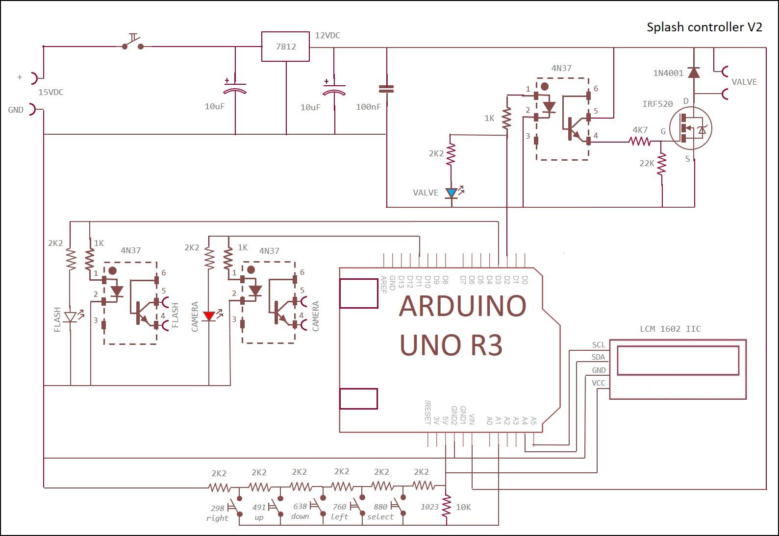
The hart of the controller is the Arduino UNO R3 computer. All neccessary components are built on a PCB, including the Mosfet for activating the valve. Three outputs are used to switch the camera shutter (D11), the flash (D3) and the valve (D2). Optoisolators are used for a safe separation between these components and the Arduino.
The optoisolator output switches with a light sensitive NPN transistor connected to pin 4 and 5. This transistor is polarity sensitive. (the emitter on pin 4 must be negative compared with the collector on pin 5. This polarity must come from the connected flash or camera. If the control leds (white, blue and red) are flashing, the Arduino activates the optoisolators in a correct way. When the camera and/or flash are not responding, try to swap the connections on pin 4 and 5.
The optoisolator for the valve switches a Mosfet to operate the valve on the 12 VDC level. I found many discussions on the internet telling the IRF520 Mosfet cannot be used with an Arduino computer because the gate voltage needs to be at least 10 VDC for full operation and the Arduino output voltage is only 5VDC....
So I used the optoisolator to switch the Mosfet gate with a level > 5VDC. It works OK.
I used a display with I2C control, this saves a lot of wiring, only four wires are needed, SDA, SCL, VCC and GND.
For the button control a chain of 2k2 resistors is connected to input A1, the software detects the analog value depending on which button is pressed. Each Arduino output also controls a led, red for the camera, blue for the valve and white for the flash. I used a 7812 linear voltage regulator for the 12 VDC connection. The display and the resistor chain operate on the 5 VDC connection of the Arduino. To make the PCB I made a drawing on A4 size paper with all components and wiring connections, moving every component around until they all fitted together.
Changes I made using the original photobuilds.co.uk design:
* start message "splash controller V3".
* 4 water drops instead of three.
* LCD type LCM1602 I2C instead of LCD 1602 keypad shield. (only 4 wires needed to be connected).
* Separate keypad with resistor chain on A1 and different Mosfet design integrated on the PCB.
* EEPROM instructions GET/PUT instead of read/write to store INT numbers >255 (these numbers need 2 bytes per number)
* "Clear valve" routine added (press DOWN button during startup, press SELECT button to stop). This opens the valve continuously.
* "test droplet" routine added (press UP button during startup, press SELECT button to stop). This opens and closes the valve every two seconds without camera control and without flash to test the camera focus.
The Water Drop Stand

.jpg)
.jpg)
.jpg)
.jpg)
.jpg)
.jpg)
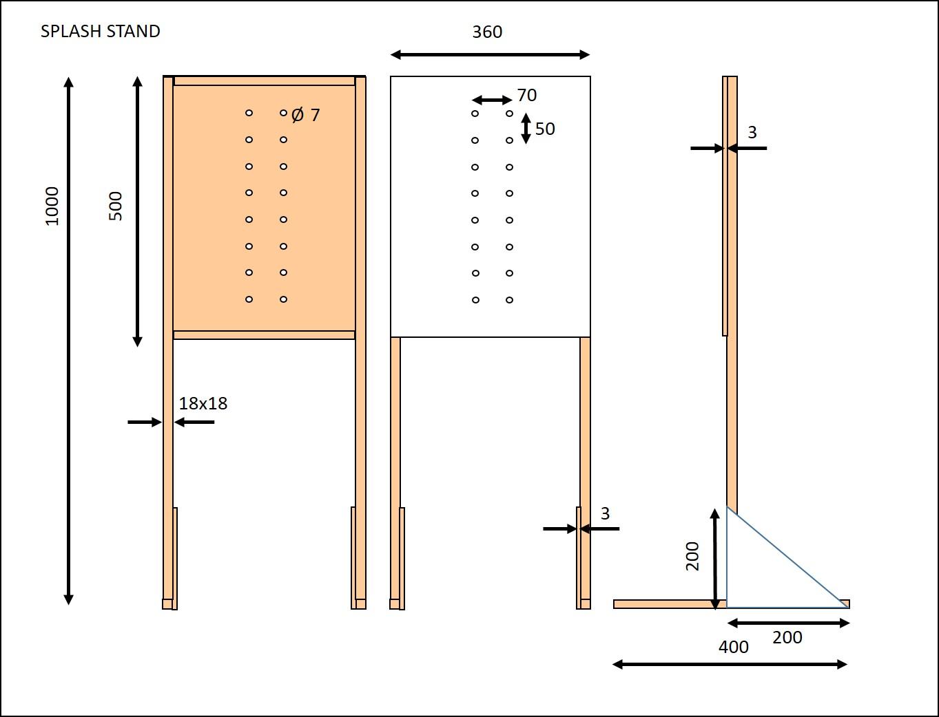
The stand is made from wood as shown in the pictures. All parts exept the triangular parts on the feet are glued.
The feet can be removed for easy storage of the stand when not in use.
White or colored background paper can be attached to experiment with the photo effects.
The Valve Holder

.jpg)
.jpg)
.jpg)
.jpg)
.jpg)
The valve holder is made from wood as shown on the pictures. It fits on the stand with two M6 bolts with knobs on the back.
Boxing in the Controller
.jpg)
.jpg)
.jpg)
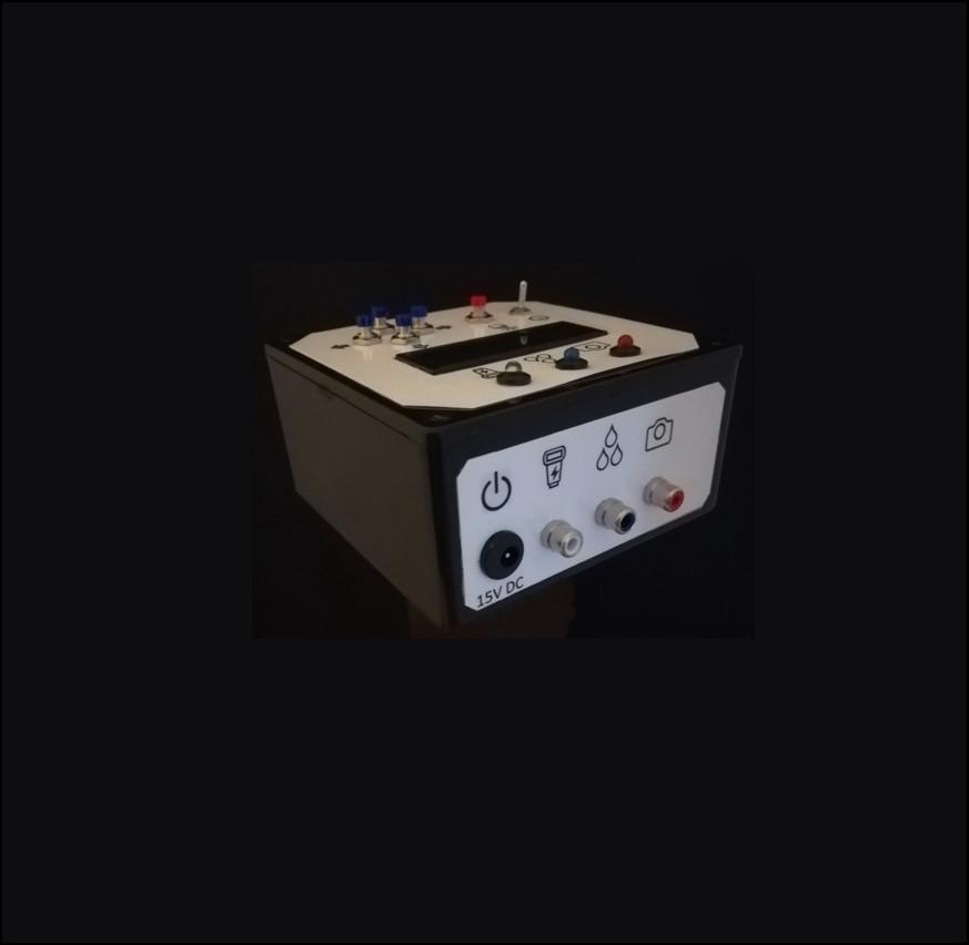
I used a black plastic box, dimensions 120x120x60 mm. to box in the controller. First I made a mounting plate appr. 110x110 mm. from 6 mm. MDF wood to mount the PCB and the Arduino. The Arduino USB PC connection can be reached throug a little hole in the side. The I mounted the switch, the buttons, the display and the RCA connectors and the power plug. Then I soldered the wiring (first outside the box for easy access). I used three wooden parts wit a 10 mm. hole, glued to the mounting plate and the cover to guide the wiring. Finally (after testing!) I added tiewraps on the wiring.
Download the hole template and drill the holes in the box. Download the white instruction menus and print these on glossy photo paper, cut them out and fix them with double sided adhesive on the box.
Installing the Software for the Controller
First copy and upload the test program from the attached file, using the Arduino IDE program.
With this program you can test the analog values on the A1 input when the pushbuttons UP, DOWN, LEFT, RIGHT and SELECT are used. The values are depending on the values of the 2k2 Ohm resistors in the chain connected to A1. Note the values on a piece of paper for each button used. No button pressed must result in a value of 1023. Check these values with the values in the controller program and change these values if needed.
This test program also writes the initial values of the number of drops, the drop sizes, the gap lengths and the flash delay time into the EEPROM memory. The number of drops is set to 4, all other values are set to 55. These values can be changed later on with the setting buttons. The three leds on the front are lit and the display is filled with 2x16 asterisks to check if it the wiring is OK.
Finally copy the controller program from the attached file into the Arduino with the IDE program.
Update November 2023:
I added a test program to test the LCD display with I2C connections only. It shows asteriks (*) on all digits of the display.
Using the Controller
.jpg)
.jpg)
.jpg)
.jpg)
.jpg)
On startup the display will show "Flash control V3" and the previous used cycle values are retrieved from the EEPROM memory.
The valve can release one, two, three or four drops, and the size of each drop can be controlled (ie. the time the valve is open) and also the spacing between drops (the time the valve is closed after each drop). While the camera output triggers at the very start of the timing cycle, a separate flash trigger output is provided for a user-defined time after the last drop is released. The action can be captured by a short bust of flash when the collisions are actually happening.
Drop size is defined by a valve opening of 1 to 99ms, and time between drops by a valve closure of 1 to 999ms: the time for a drop to fall is going to vary with the height of the dropper, so it seems like a good idea to allow a period of up to nearly a second between drops for flexibility. Flash delay is also programmable in the range 1 to 999ms.
Programming the system is fairly simple: scroll through the options using the up/down keys and when the parameter you want to modify is on the top line of the display, select it using the select key. You can then modify its value using the up and down keys, and can change the size of the increment decrement with the left and right keys. Hitting the select key again allows you to go back to scrolling through the parameters. If you press the select key when “Fire Flash!” is on the top line of the display, the current parameters are written to the on-board EEPROM, the display backlight turns off and the trigger cycle you’ve programmed commences. Also the colored leds on the front will flash showing the cycle action. When the trigger cycle is complete the backlight turns on.
Additional it is possible to clear the valve and empty the siphon (when colored water is used you can change the water content this way). To do this just press the DOWN button during startup. The display will show "clear valve" and the valve will open until the SELECT button is pressed.
Setting the camera focus:
Press the UP button during startup. The display will show "test droplet" and a drop will fall every two seconds, without camera command and without flash. Stop this test mode by pressing and holding the SELECT button.
Cable Connections

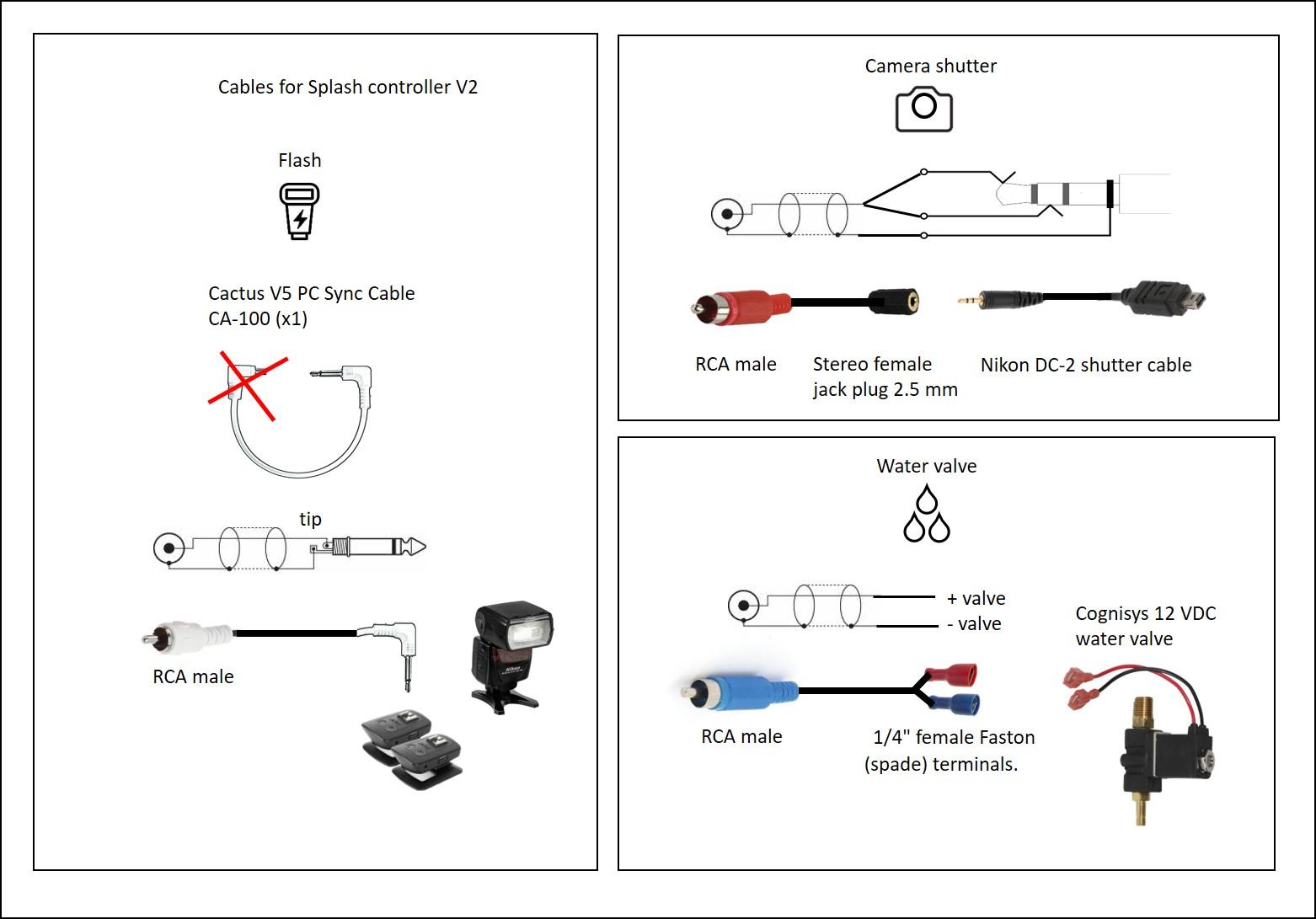
See attached picture for the technical details.
The flash connection cable:
I used the PC-sync cable that came with the Cactus V5 remote flash trigger set and replaced the flash connection with an RCA male plug.
The water valve connection cable:
I made a cable with an RCA male plug on one side and two Faston connectors on the other side.
The camera connection cable:
I used a standard Nikon DC-2 remote shutter cable and made an extension cable with an RCA male plug on one side and a 2.5 mm. stereo female jack plug on the other side. Both internal (stereo) wires must be connected to the RCA middle connection.
Guidelines to Make Bouncing Droplet Photos
.JPG)
.JPG)
.JPG)
Some guidelines you could use:
Find a location for your creative photography. Your kitchen or bathroom are ideal places. You cannot avoid one or two splashes of water ending up outside the bowl. A place where you can quickly clean up will make this shoot more fun.
Use plain boiled or demineralised water and no additives in the siphon which I think is safer for the valve.
Fill the mixing bowl with water almost completely. Add a few drops of milk to cloud the water. There are two reasons for this.
First, milky water absorbs light better than clear water. This allows you to use your flash on a low power setting and only light up your water drop.
Also, a non-transparent liquid will provide a more uniform, pleasing background. The viewer’s eyes will inadvertently jump to the droplets, and not be distracted by a messy background.
You can also add some guar gum or xanthan gum to improve the consistency of the water. Guar gum (E412) is great for thickening the water but might leave lumps in the liquid. You get better results with xanthan gum, but the additives are optional.
After the milk, add some food dye to the bowl to create a unique, colourful background. Don’t add anything to the water you’re going to drop.
Put the controller in test mode (press UP button during power on) to get a drop every two seconds. (this is without camera command and without flash). Set the camera focus to manual.
When dropping the liquid, aim for the closest part of the bowl to the camera. This way, you’ll be able to only include the water and drop itself in the frame. Without background distractions, such as the bowl.
Take a bolt M5 with sufficient length and place it upside down in the water bowl where you expect the drop to fall.
Let the droplets land exactly on the bolt by moving it into the right spot.
Finally focus the camera on the bolt. Remove the bolt. Do not change the position of the camera.
Reset the controller, set the camera on bulb mode with an aperture of F8 and the ISO setting on 100.
Set your flash on minimum power.
Darken the room and start making pictures. Main ingredients are experimenting and patience.
The camera will start the exposure by opening the lense and a picture will be taken when the flash fires.
Play around with the aperture and ISO settings to get the correct exposure.
Start changing the settings of the controller to get two or three bouncing droplets.
After finishing a session I think it is a good idea to clean the siphon and the valve with plain demineralised or boiled water.
The Flash Holders
.jpg)
.jpg)
The main flash is mounted on a small platform with an M8 threaded rod together with the Cactus V5 receiver. The slave flash is mounted upside down at the back of the valve rig and flashes through a rectangular reflector made from cardboard. This reflector has colored diffusor sheets (red, white, green, blue and yellow).
Additional Information
.JPG)
.JPG)
Technical information (attached PDF files) from the remote flash system Cactus V5 and the Cognisys water valve.