SpyBot Using 4Duino-24
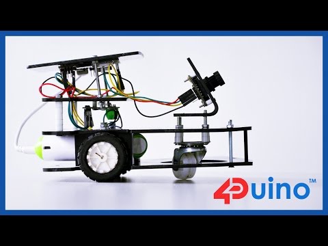

4Duino SpyBot project demonstrate how does uCAM-II works. This project also utilized two 4duino communicating using Server-Client architecture over TCP. It also uses a buggy car which carry the 4duino server and uCAM-II. By using built-in ESP8266, 4duino client sends a request to 4duino server to move the buggy and capture photo via wireless communication.
uCAM-II is an integrated serial camera module. This is attached to the server 4duino as its host to enable image capturing feature of this project. This module uses a CMOS VGA colour sensor along with JPEG compression chip. This camera uses a simple serial protocol. Please refer to uCAM-II Demo which shows how to interface 4duino to uCAM-II and capture jpeg images then store it in the uSD card.
How It Works

Server-Client architecture is a network architecture which separates devices and application programs into two categories clients and servers to better employ available computing resources and share data processing loads. Initially, client uses the network as a way to connect and then sends a request. The server will take the request and makes sure that the request is valid. If valid it fetches the request and serves the client.
In this project, TCP is used. Transmission Control Protocol or TCP is responsible for providing a reliable communications between hosts and processors on different hosts, it manages message acknowledgment and retransmissions in case of lost parts. Thus there is absolutely no missing data. In TCP, data can be sent bidirectional.
4duino client sends a request to 4duino server to move the buggy and capture photo via wireless communication.
BUILD

Complete the following components:
- 4duino (2 items)
- uCAM-II
- Buggy Robot
- Jumper cables
- 5V power supply
- micro USB cable
- uSD Card
Connect the components as shown in the fritzing diagram.
Program

Workshop 4 – 4Duino Extended Graphics environment is used to program this project. This project requires the Arduino IDE to be installed as Workshop calls the Arduino IDE for compiling the Arduino sketches. The Arduino IDE however is not required to be opened or modified to program the 4Duino.
- You can download the code here. Open the files using Workshop 4.
- Simply change the SSID and the PASSWORD to suit your router, on both the program.
- Upload (Client) Connect the first 4Duino (Client) to the PC using uUSB cable (similar to Arduino). Then navigate to the Comms tab and select the Comms port to which the Client 4Duino connected.
- Now click on the “Comp’nLoad” button on Program1 (Client).
- The Workshop 4 IDE will prompt you to insert a µSD card to the PC in order to save the widget images. Since we do not used widgets or any special objects for the server, click “No Thanks”.
- Upload (Server) Similarly, connect the second 4Duino (Server) to the PC using uUSB cable (similar to Arduino). Then navigate to the Comms tab and select the Comms port to which the Client 4Duino connected. Now click on the “Comp’nLoad” button Program2 (Server). Workshop 4 IDE will prompt you to insert a µSD card to the PC in order to save the widget images. Click “OK”
- Connecting Power Supply Apply a portable 5V power supply to the 4duino used as Server. Use the micro usb cable to connect it to 4duino. You can also apply 5V supply to the client if you want to use it away from your pc.
Demo


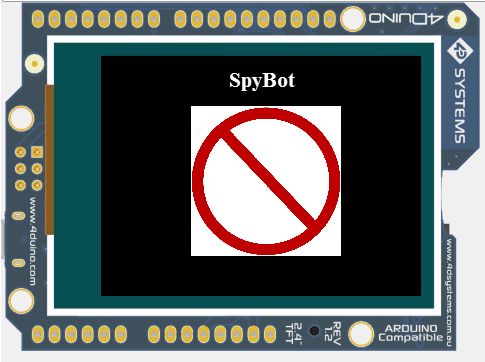
After uploading and assembling, you can control the SpyBot using the 4duino Client. You can control where the SpyBot should go and capture image.
In this project, we made the chasis of the robot car using acrylic and laser cutter. But you can easily buy a ready made robot chasis.
If you want more cool stuff, visit 4Duino Projects. Enjoy !!!