Stability Chair
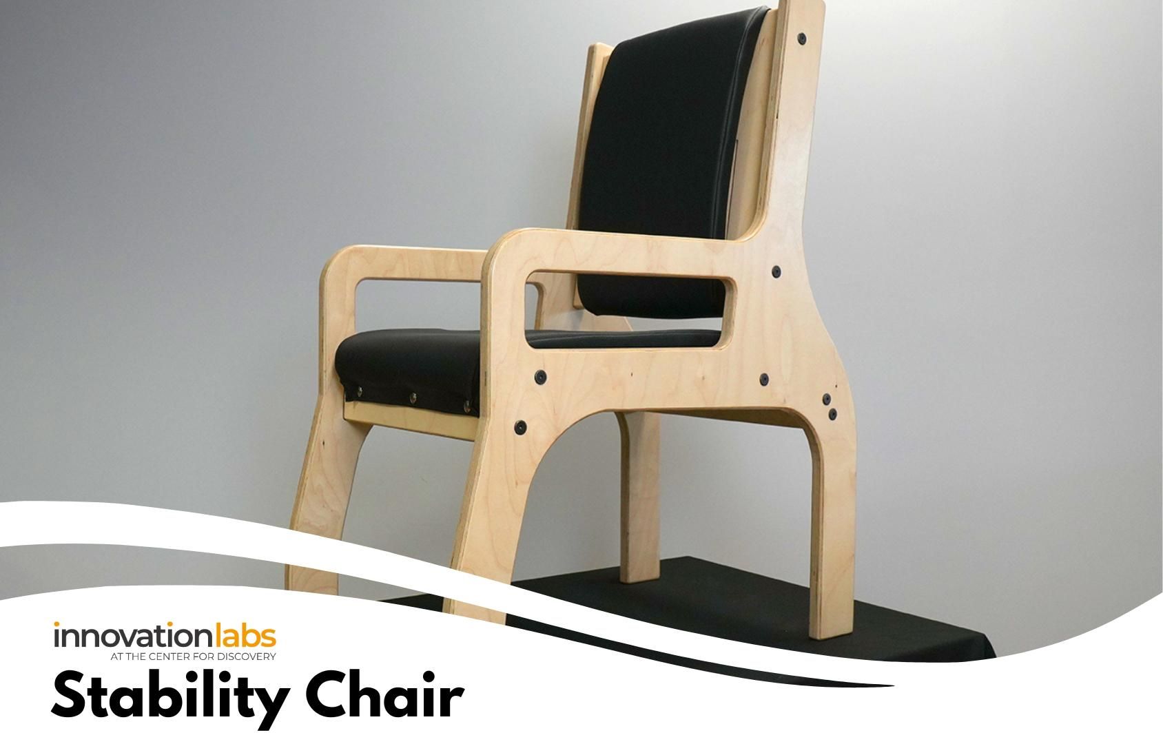
The Stability Chair is ideal for individuals with sensory-seeking behaviors, particularly in rocking or active movement patterns, who need a highly stable chair that reduces tipping risk and supports safer seating. This project addresses a critical safety gap by providing a durable, low-cost chair that is difficult to tip, supports posture and movement, and improves safety for users in everyday settings.
Estimated Build Time: 3 hours total (1.5 hours machine; 1.5 hours assembly)
Supplies
Tools:
- Protective glasses
- PC or MAC I7 +
- Measurement tool
- Clamps
- Screwdriver set
- Cutter
- Hammer
- Pull saw
- Jigsaw
- CNC Machine
Materials:
- 1 x Baltic Plywood (1" x 5' x 4' ft)
- Requires very flat Baltic plywood; must be a true 1" thickness, with thickness varying by no more than 1/16". Recommend to use your local supplier.
- 14 x Binding Screws for Wood (1/4"-20, 1.181" Thread Length, 1.969" Long,.669" Head in)
- 14 x Dowel Nuts for Wood (1/4"-20 Size, 0.472" Long in)
- 1 x Steel Slotted Spring Pin (5/8" Diameter, 3" Long in)
Final Dimensions:
36"H x 27"L x 18"W
Before You Begin...
Carefully read the instructions and ensure that you have all the required tools, materials, and correct measurements before you start building the device. Always wear protective gear when working with tools.
Determine Your Chair Size
There are three chair sizes available: 14", 16", and 18". These measurements refer to the width of the chair seat. Before loading the CNC for cutting, measure the intended user’s seated width to determine the most appropriate chair size.
Prepare CNC Paths
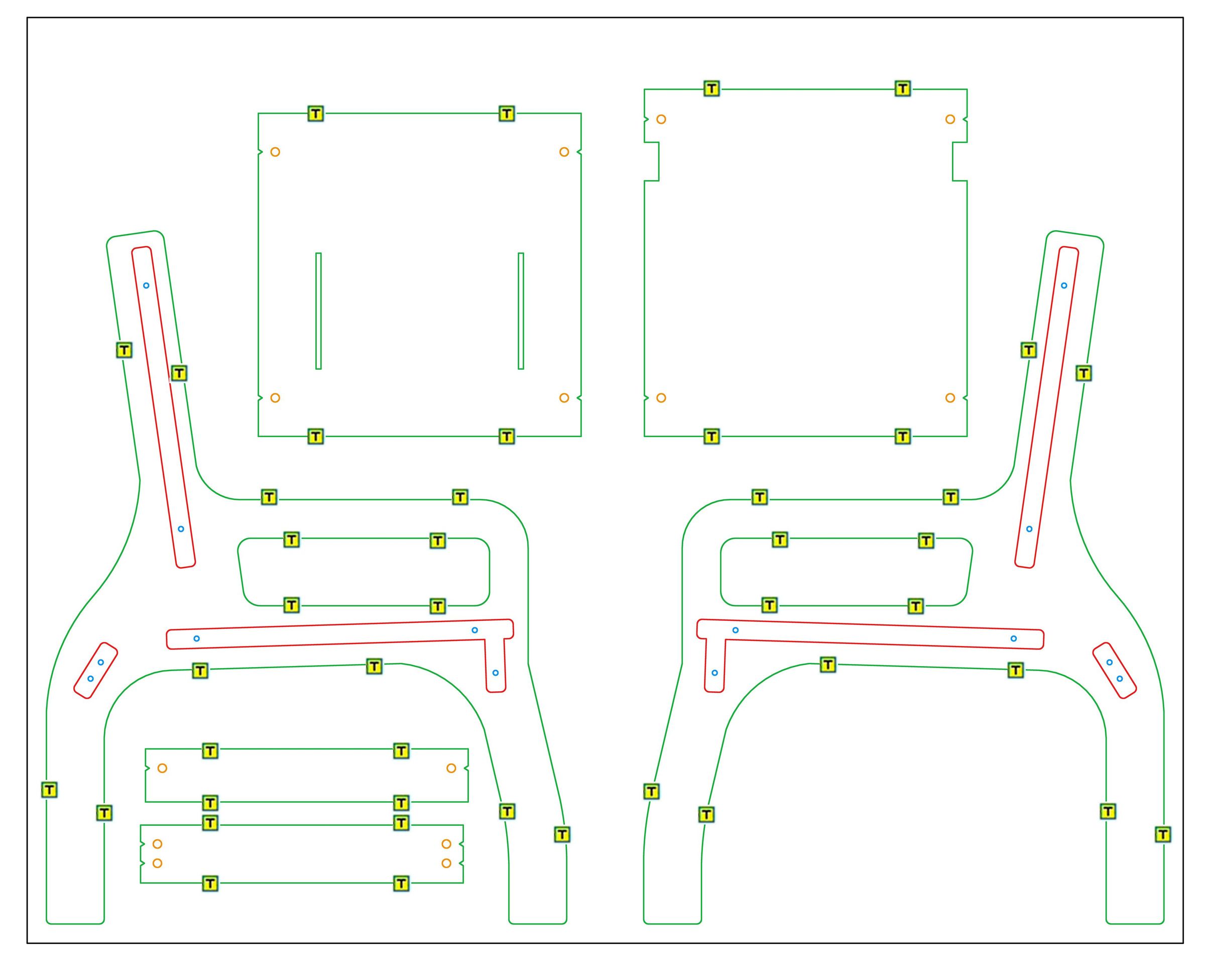
Use the attached DXF file corresponding to your intended chair size (14", 16", or 18") to generate the cut paths for your CNC machine.
CNC Cut Sequence
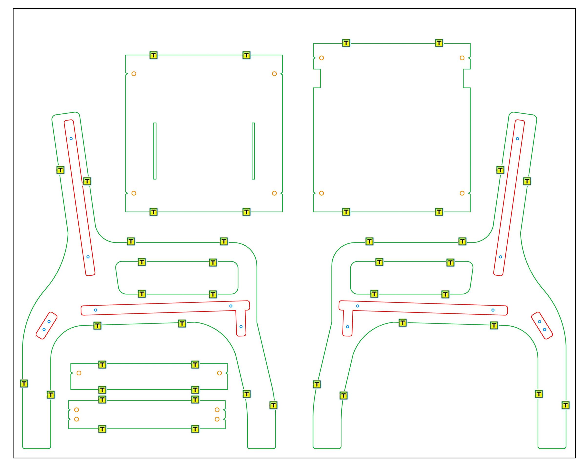
Use a 1/4" bit for all cut paths and follow the cutting order below: Pocket cut the 6 red vectors to a depth of 3/8" from the top surface of the material. Pocket cut the 14 orange vectors to a depth of 3/4" from the top surface of the material. Drill cut the 14 blue vectors to a depth of 1 1/16" from the top surface of the material. Profile cut along the outside of the 8 green vectors to a depth of 1 1/16" from the top surface of the material. Add at least four evenly spaced tabs to each vector, as indicated by [T].
Remove Cut Parts
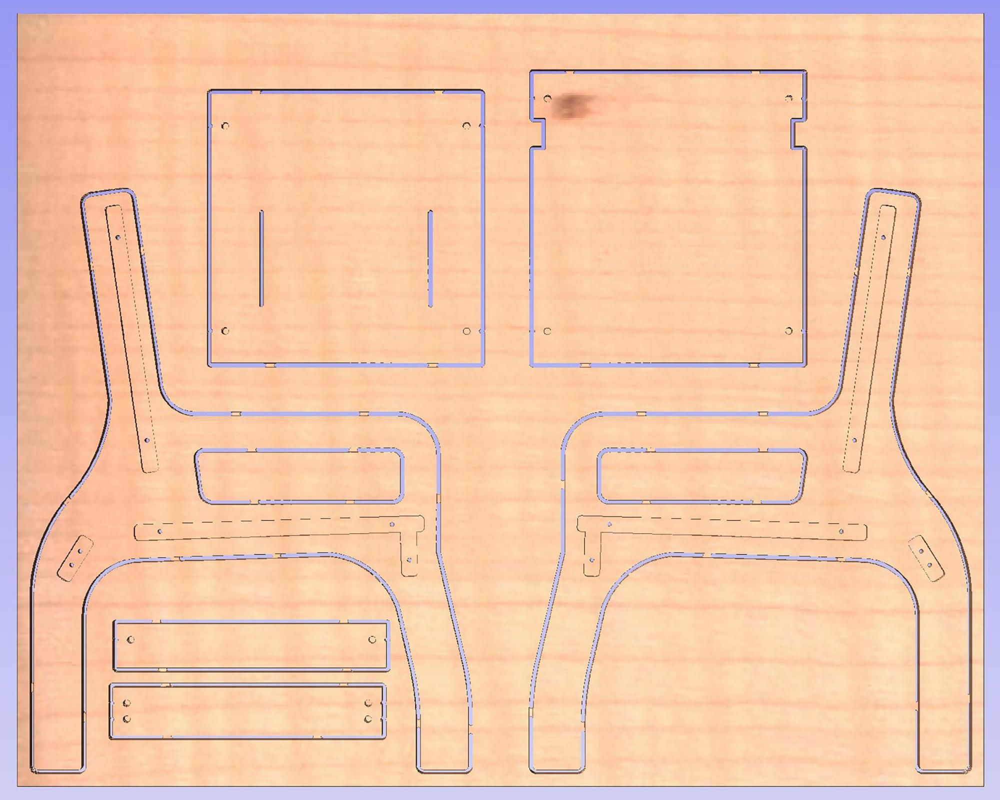
Use a multi-tool or jigsaw to cut through the tabs and free the six plywood pieces from the sheet. Make each cut flush with the part edges so the tabs are completely removed from every piece.
Round & Sand Edges
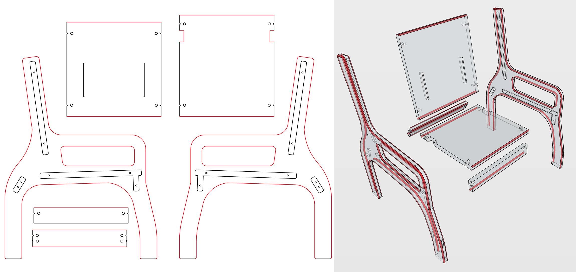
Use a handheld router with a quarter-round bit to round over the edges on both the front and back sides of each piece, as indicated in the photo in red. Then sand all surfaces of the six pieces with a random orbital sander until smooth to the touch.
Drill Side Holes
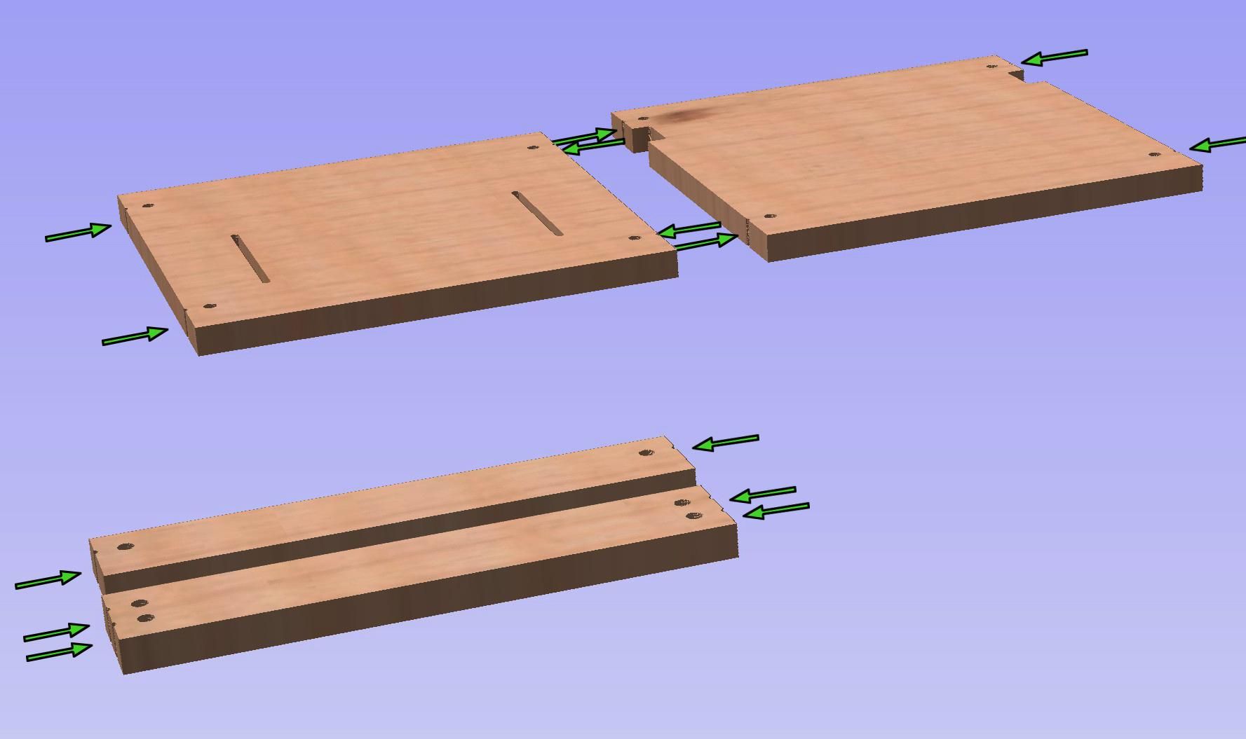
The next step is to drill the 14 holes, as indicated in the photo, into the side walls of the four middle pieces. These holes connect the round pockets for the dowel nuts (the 14 orange pockets in your CNC file). To ensure accurate placement, use a simple drilling jig to guide the 3/8" holes into the side walls.
Build Your Drill Jig
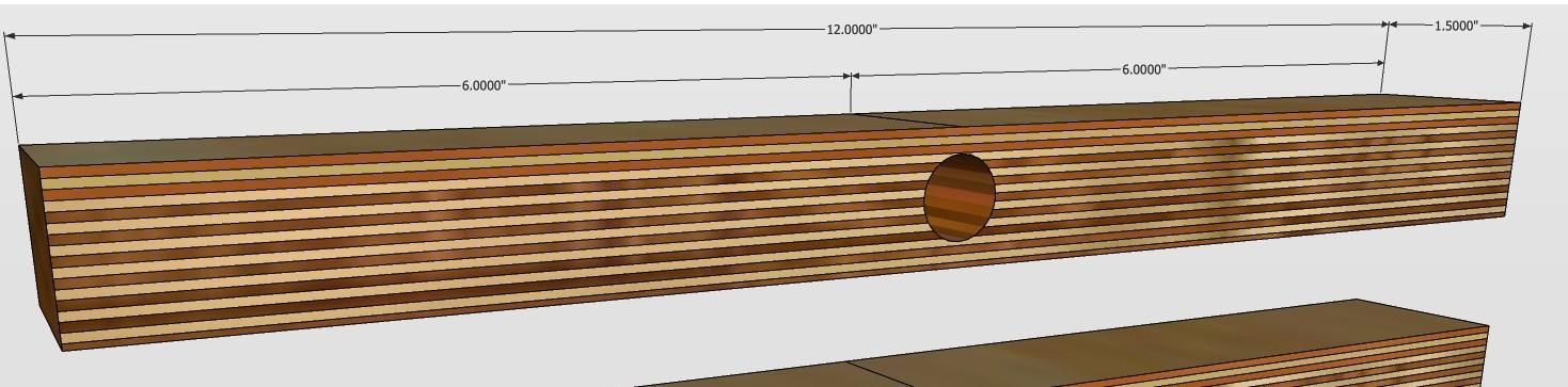
Using leftover Baltic plywood, cut a rectangle measuring 1.5" × 12". Using a drill press, drill a 5/8" hole through the middle of the side of the plywood piece. Ensure the hole is drilled at a true 90° angle and positioned exactly halfway through the thickness of the rectangle, as shown above.
Install Spring Pin
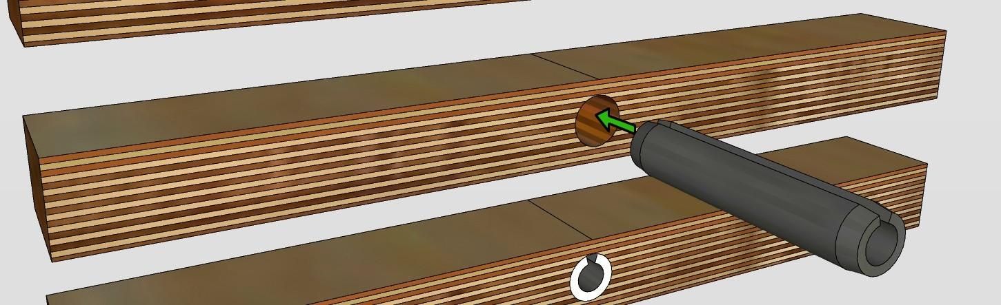
Using a hammer, drive the spring pin into the hole so that the pin sticks out of both ends of the hole.
Cut the Spring Pin Flush
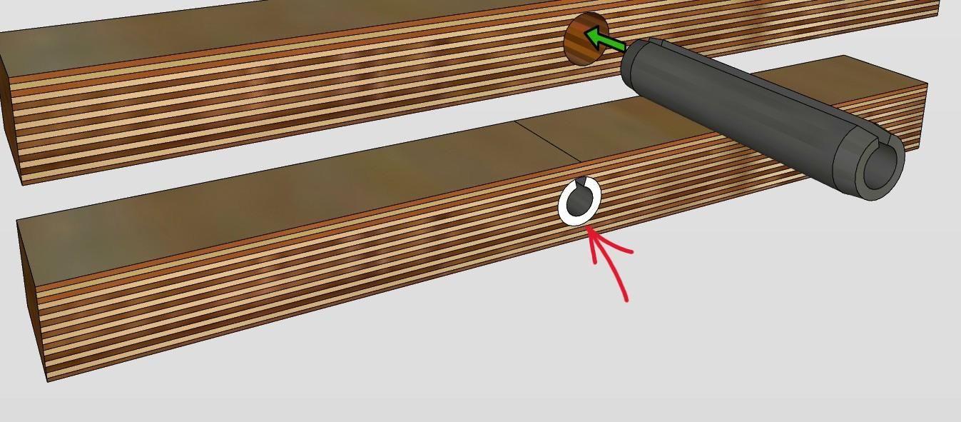
Using a hacksaw, cut the pin so that it is flush with both sides of the plywood.
Secure With a C-Clamp
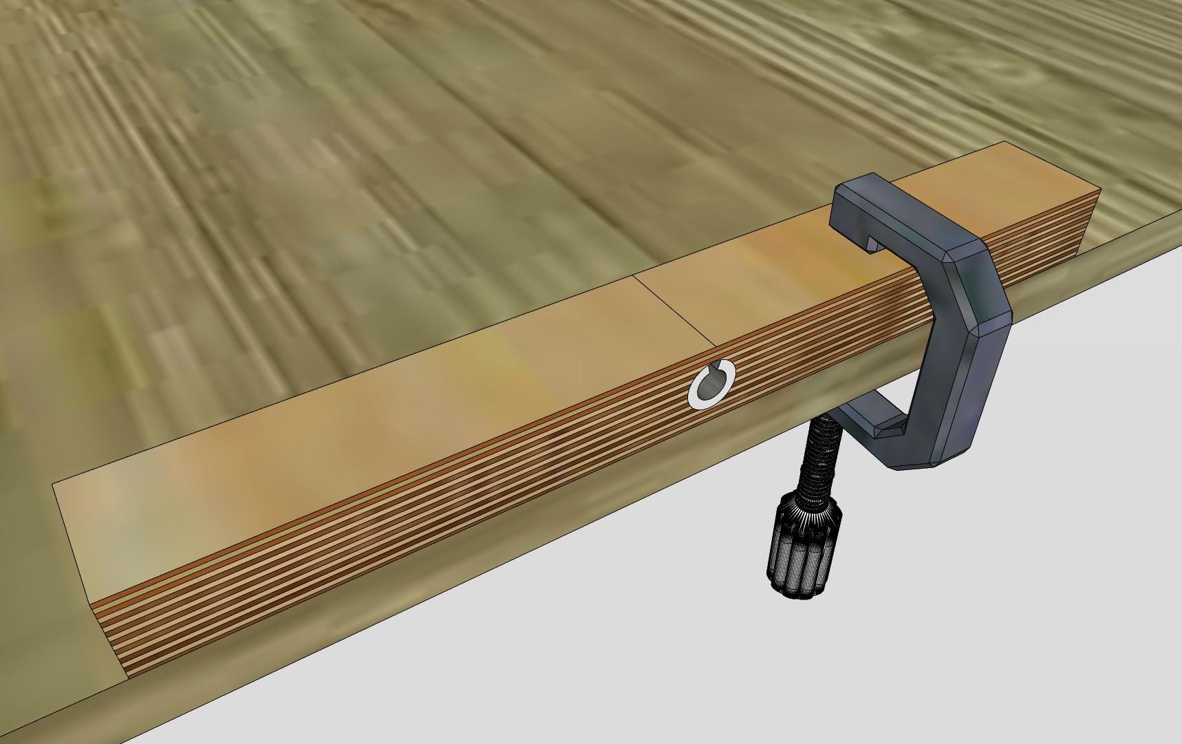
Using a C clamp secure the jig to the edge of the work table, as shown.
Align Drill Jig
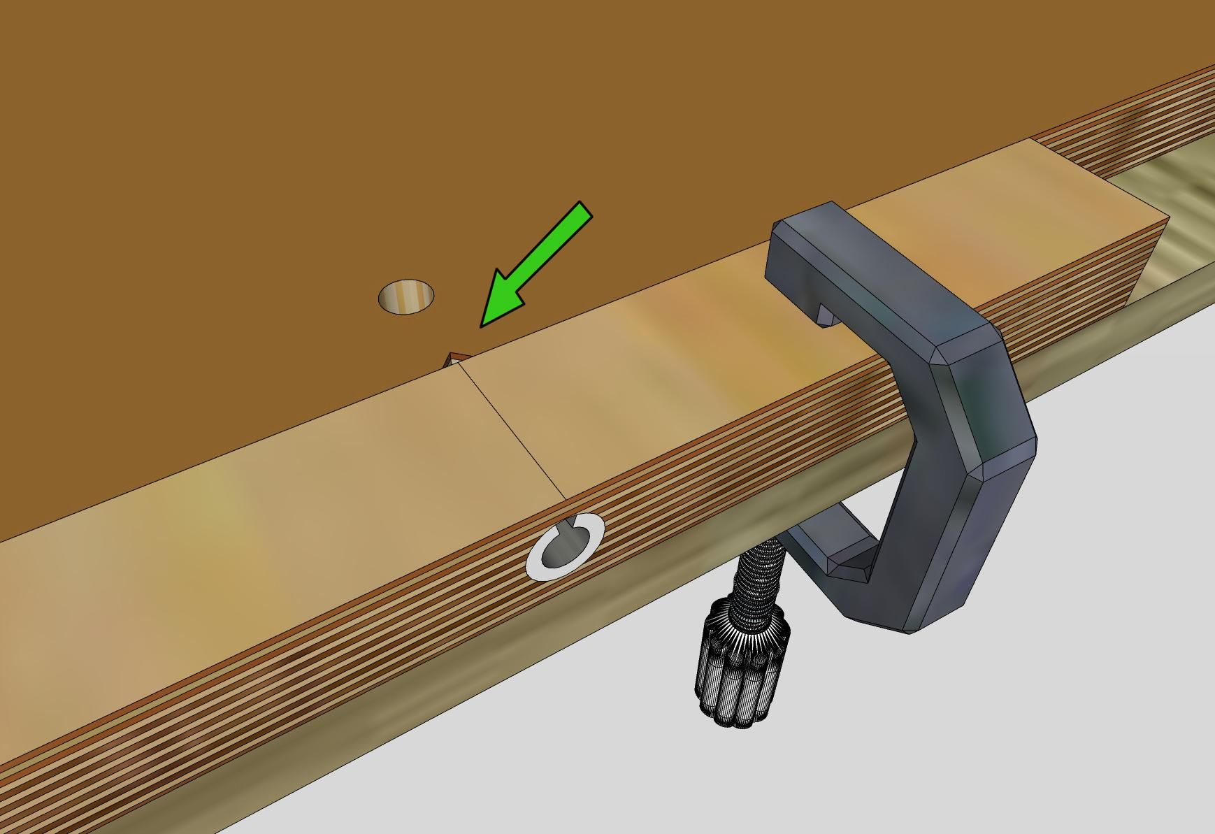
Use the notches on the sides of the middle pieces to align the dowel nut pockets with the hole in the jig, as shown here. Make sure the work piece is pressed firmly against the jig before drilling.
Drill Dowel Holes
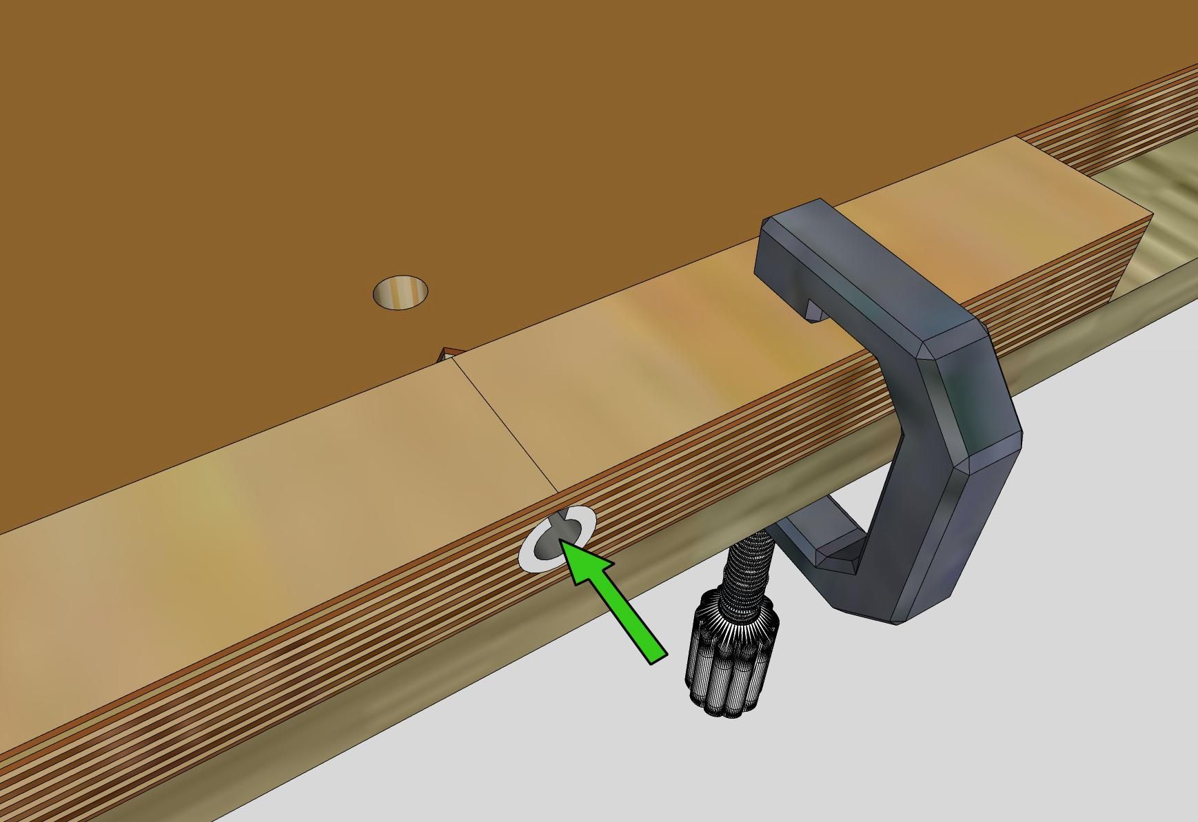
Using a 3/8" drill bit and the jig as a guide, drill the 14 side-wall holes into the dowel nut pockets on the four rectangular middle pieces. After drilling, remove any sawdust or debris from the holes.
Assemble the Frame
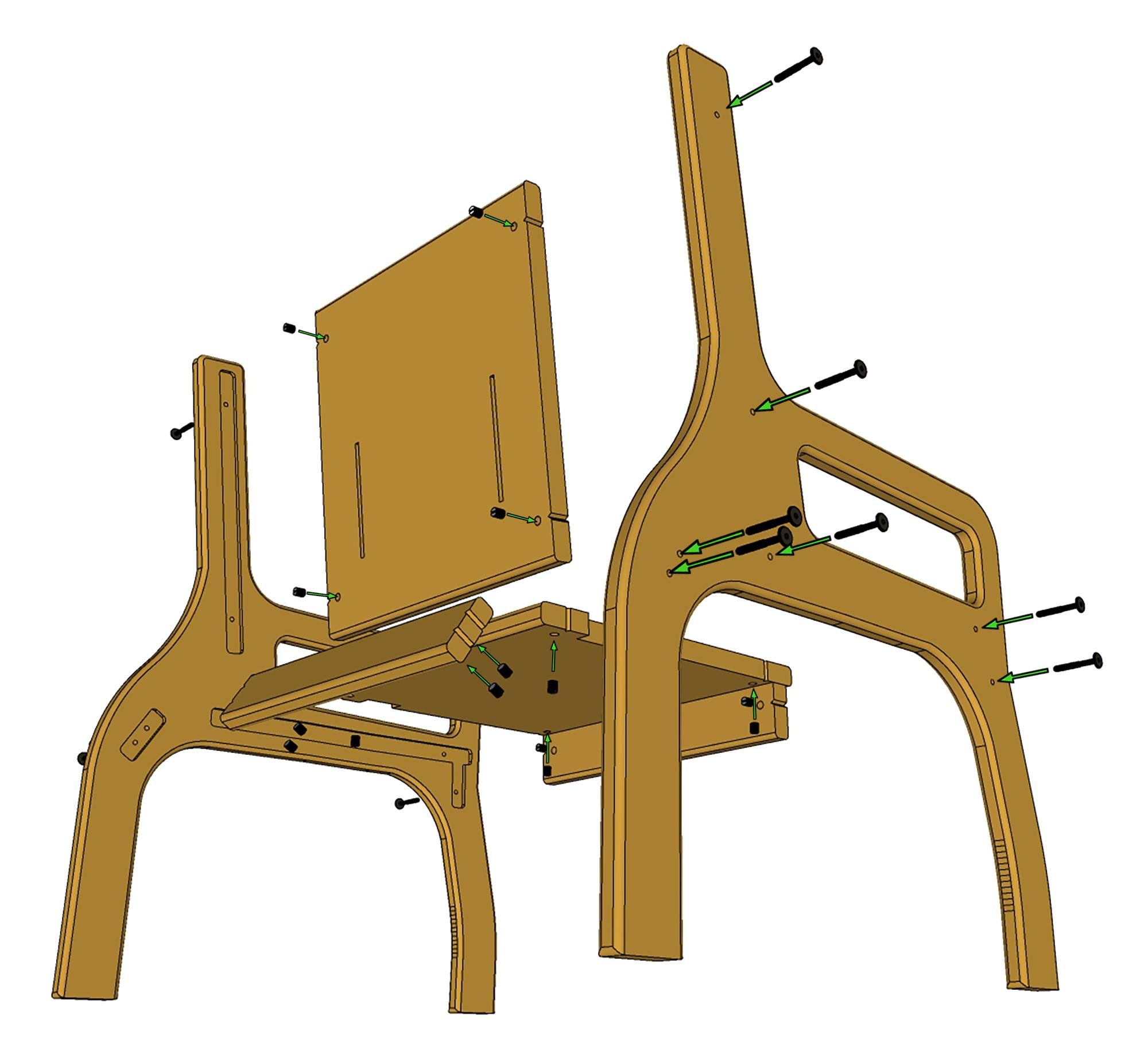
Hammer the four middle pieces into their corresponding pockets in the two chair-shaped side pieces, using a block of wood to protect the surfaces from direct hammer contact. Next, insert the 14 dowel nuts into their pockets in the middle pieces. Finally, insert the 14 binding screws through the side pieces and tighten them into the dowel nuts using a 5/32" hex bit, as shown here.
Optional
For increased durability, apply at least two coats of polyurethane to all wood surfaces, allowing proper drying time between coats as recommended.
Build Complete!
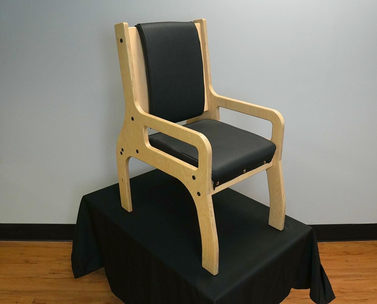
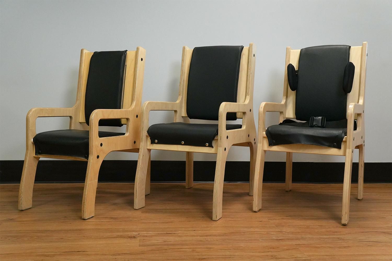
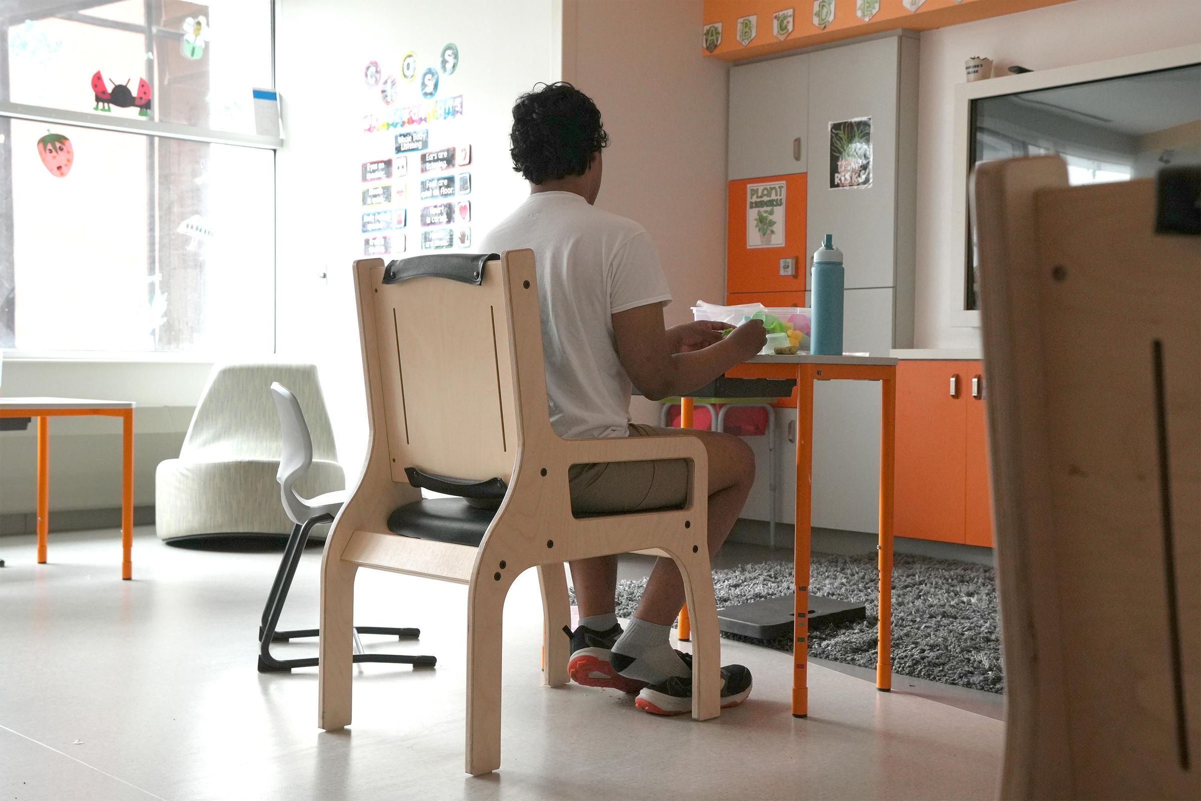
Congratulations! Your chair is fully assembled and ready to use. The chair can be used without cushions, though aftermarket cushions with tie straps may also be used for added comfort and fit.
If this project interested you, give us a favorite and drop a comment below.
Thanks for building with us!
DISCLAIMER: The Center for Discovery, Inc. (TCFD) works with Instructables to make the following information available for informational purposes only. TCFD, its agents, successors and / or assigns make no express or implied warranty of fitness or merchantability for any particular purpose for the items depicted. The reader should understand that the construction of this item is intended for use by an individual with cognitive or physical impairments (end user). This may pose a higher risk of injury to the end user. TCFD advises there is also a risk of injury to the individual constructing the device. The reader agrees to undertake the appropriate steps to lessen or eliminate risks of injury occasioned by the construction or use of the items depicted. Any and all losses, injuries or damages incurred by or resulting from the use of the information in this publication are the sole responsibility of the reader and end user, all of whom voluntarily, expressly and completely release, forever discharge, and agree to defend, indemnify and hold harmless TCFD, its agents, successors and / or assigns, from any and all claims, demands, or causes of action, which are in any way connected with the use of the information contained in this publication.