StackFM

Greetings, everyone and welcome back
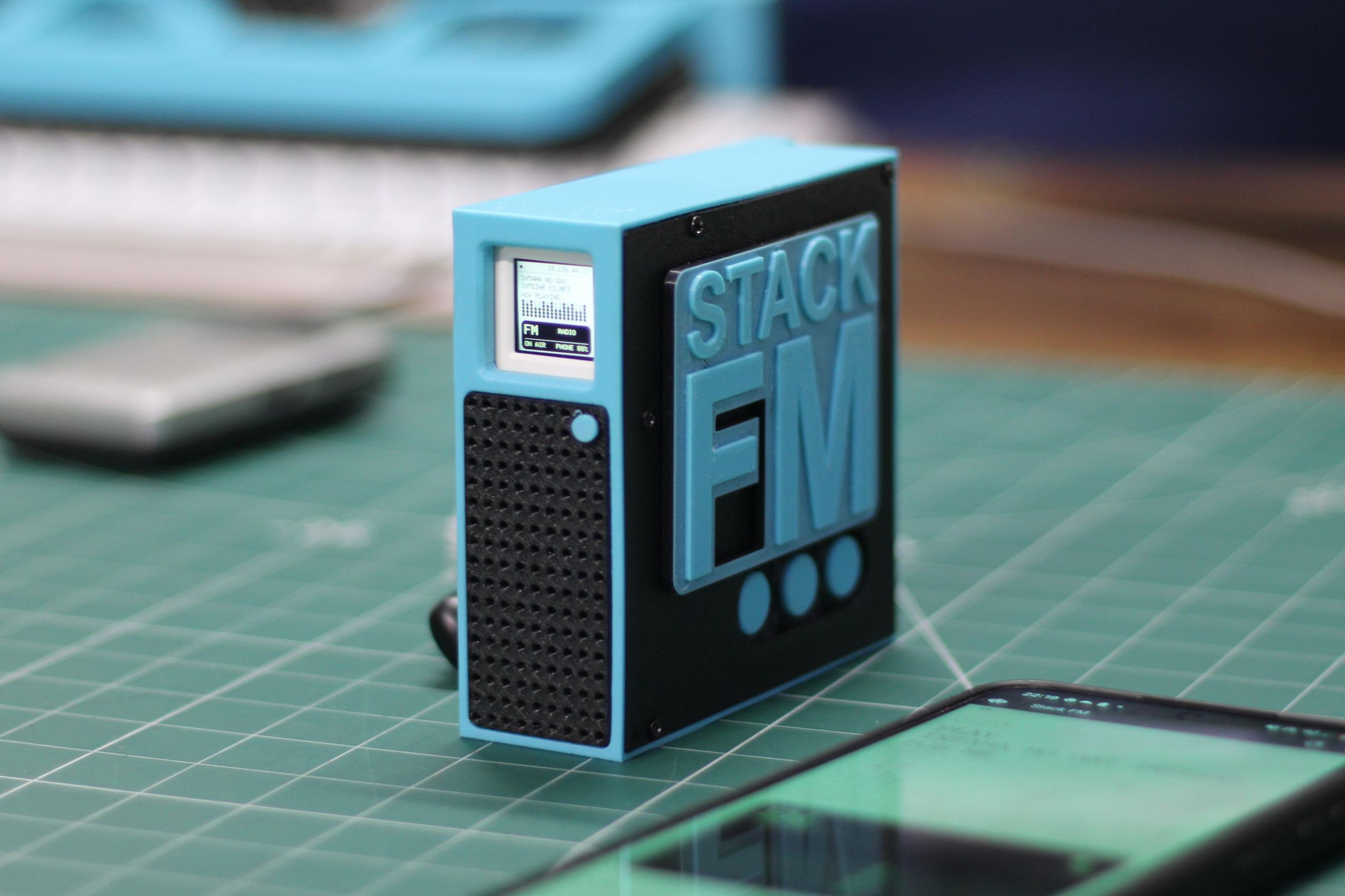
This is StackFM, a compact Wi-Fi radio buGreetings, everyone, and welcome back!round the M5Stack AtomS3, a MAX98357A I2S audio amplifier, and a speaker.
The idea behind this project was to turn the tiny AtomS3 into a proper desk radio, something that could connect to internet radio streams, play them through its own speaker, and still have a simple physical interface.
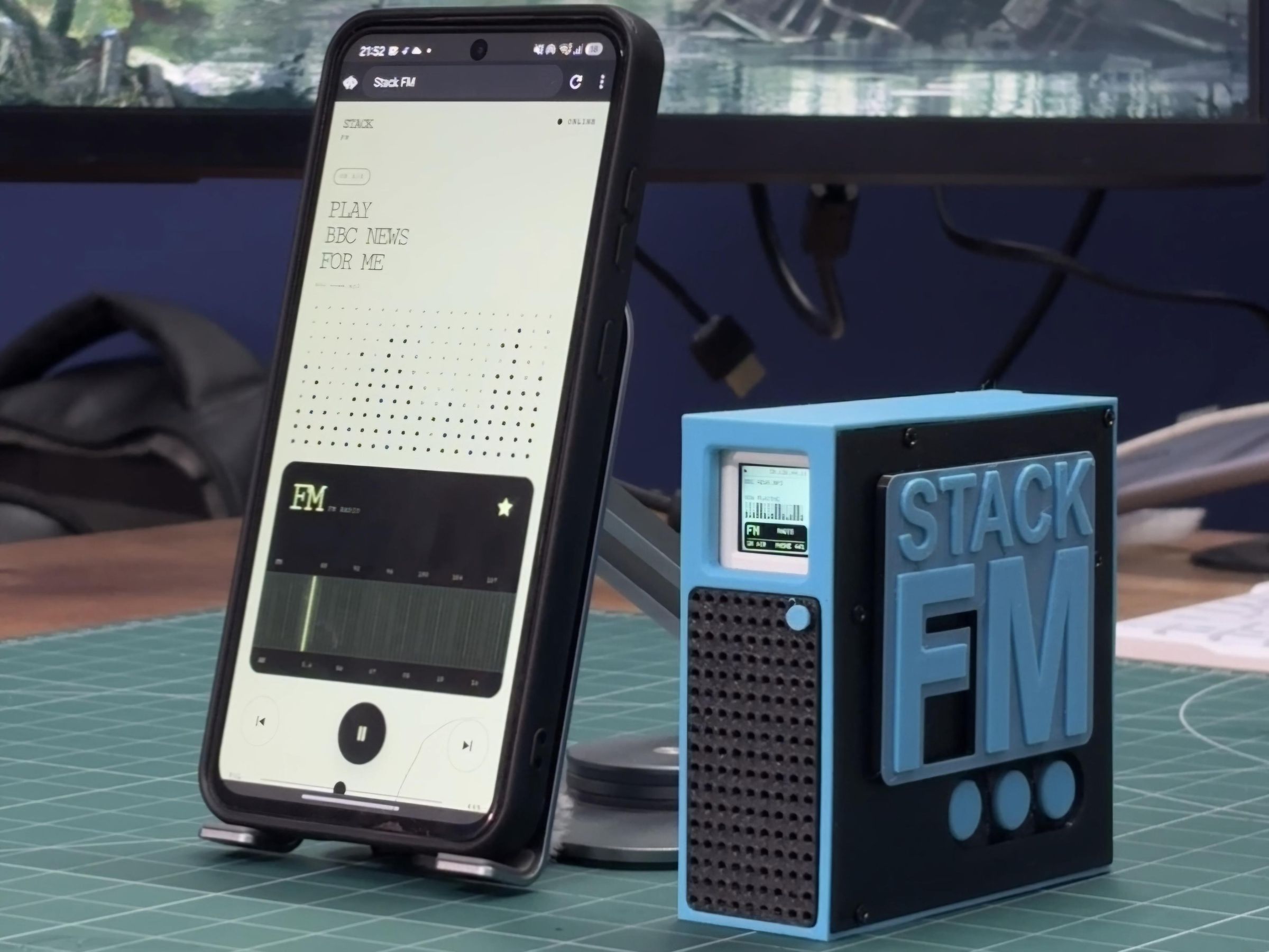
Instead of trying to fit every control onto the AtomS3's 128 × 128 display, I created a custom webpage for the radio. The webpage can be opened from a phone or computer connected to the same Wi-Fi network. From there, I can add stream URLs, save stations, select what I want to hear, control playback, and adjust the volume.
The important part is that the phone is only being used as a wireless controller. It does not play the audio. Once a station is selected, the AtomS3 connects directly to the stream and sends the audio to the MAX98357A amplifier, which drives the speaker.
I also wanted the device to feel like an old FM radio, even though it is actually receiving stations over Wi-Fi. This led to a retro-style interface for both the radio display and its browser controller.
This Article covers the complete build process of this project. So, without further ado, let's get started!
Supplies
MATERIALS REQUIRED
- M5Stack AtomS3 with built-in 128 × 128 display
- MAX98357A I2S digital audio amplifier
- External speaker compatible with the amplifier
- Custom StackFM PCB
- IP5306 power-management IC
- 10 µF capacitors, SMD 1206 package
- 10 kΩ resistors, SMD 0805 package
- 1 µH SMD inductor
- 0805 indicator LED
- USB Type-C port
- Push switch
- 3D-printed StackFM case and enclosure parts
- Jumper wires or short hookup wires
ATOMS3 AND AUDIO SETUP
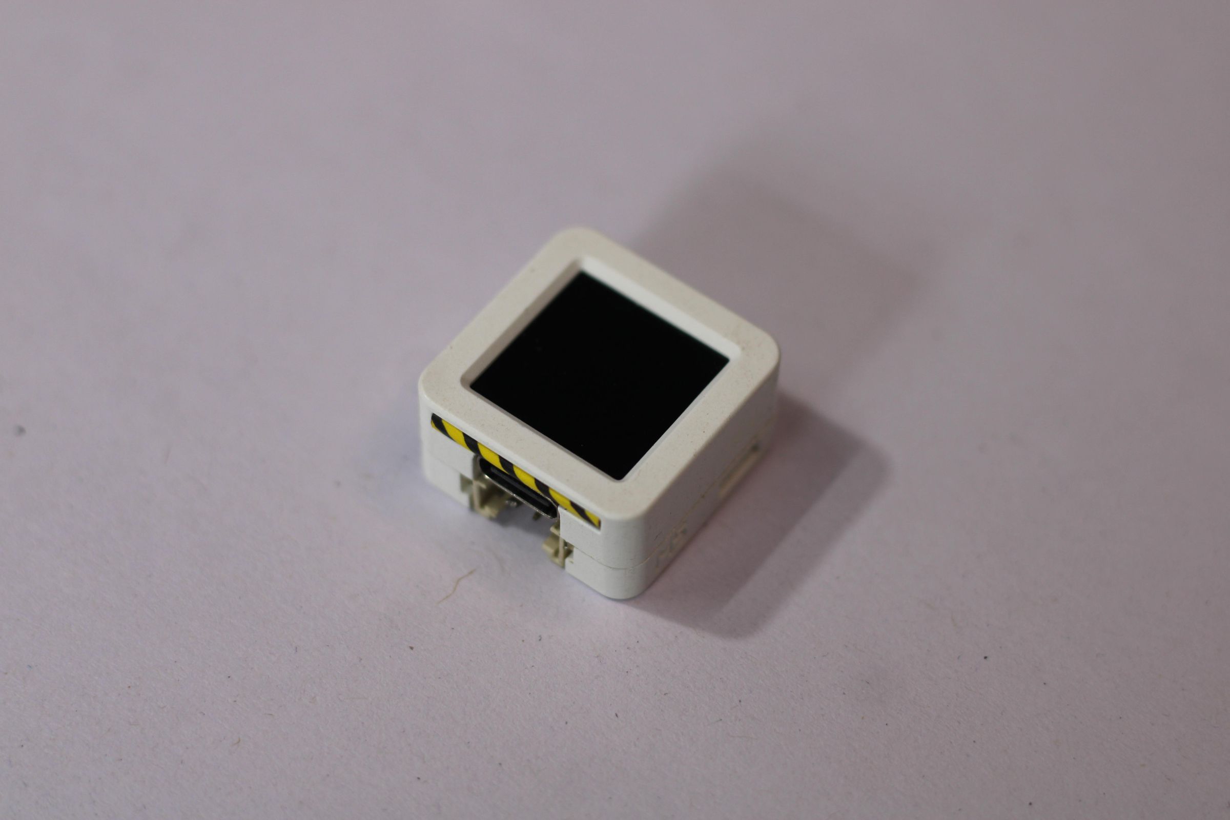
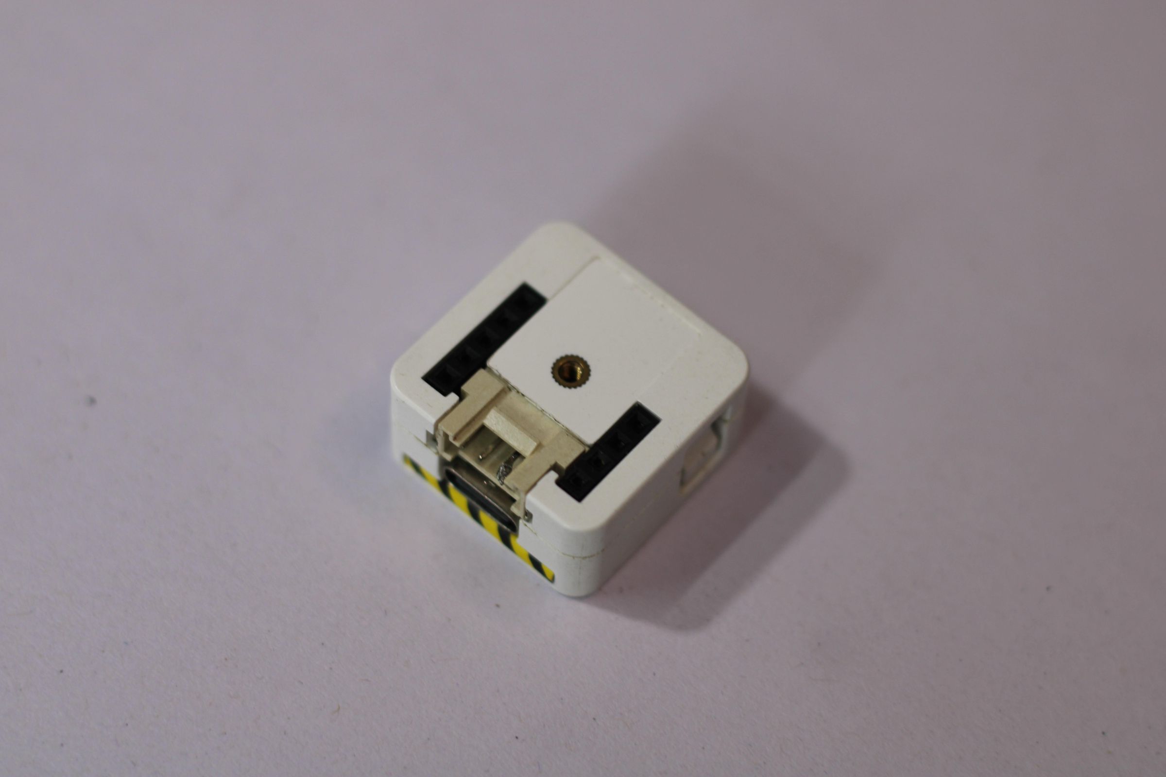
The M5Stack AtomS3 is the brain of StackFM. It connects to Wi-Fi, hosts the webpage, receives commands, opens the audio stream, updates the display, and sends digital audio to the amplifier.
Audio is sent using I2S, which uses three main signals:
- BCLK — audio bit clock
- LRC/WS — word selection
- DIN — digital audio data
The MAX98357A receives these signals, converts the digital audio, amplifies it, and drives the speaker.
MAX98357A AND SPEAKER
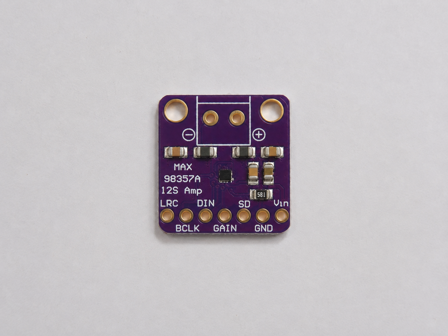
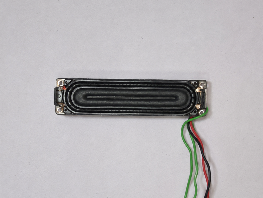
The MAX98357A accepts I2S audio directly from the ESP32-S3, so a separate DAC and amplifier are not required.
The speaker connects between SPK+ and SPK-. Neither speaker terminal should be connected to ground because the module uses a bridged output.
I kept the I2S wires short during testing and made sure the AtomS3 and amplifier shared the same ground.
DESIGN
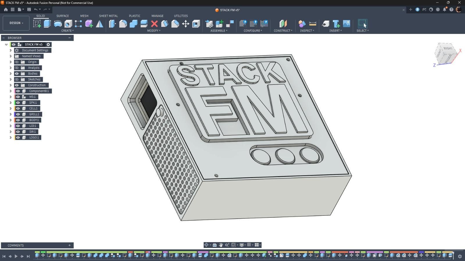
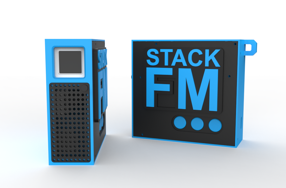
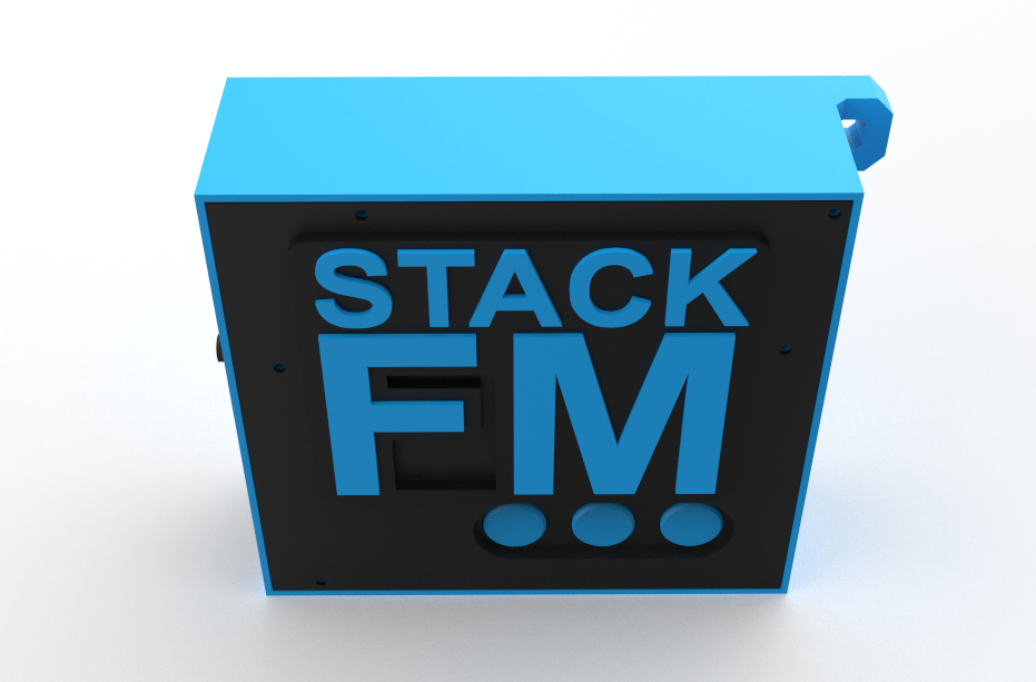
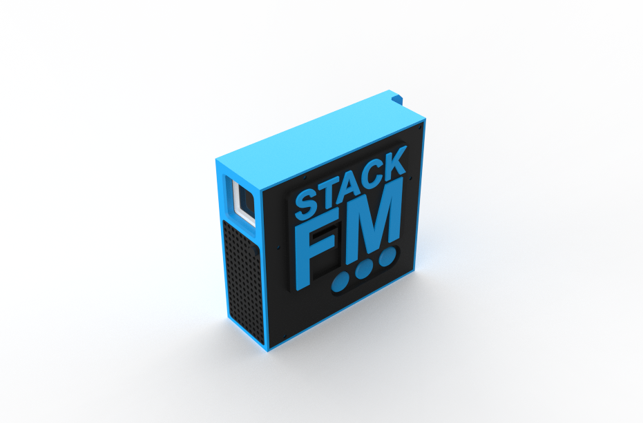
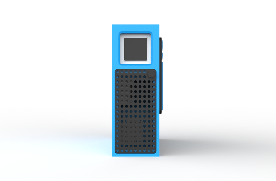
For the design of Stack FM, I wanted to make it look like a small desk radio rather than a normal electronics enclosure.
The body was kept compact and boxy so all the parts could fit inside properly, while the front side was designed as the main visual face of the project.
The front panel uses a black faceplate with a raised STACK FM logo on top. I printed the logo in a blue/cyan color so it stands out clearly against the black background. The same blue color is also used for the outer body and buttons, which gives the whole device a clean two-tone look.
On the lower side of the front panel, I added three circular buttons. These buttons make the device feel more like a proper radio, instead of something that is only controlled from a web app.
One side of the enclosure also has a speaker grille section so the sound from the internal speaker can come out properly. This was important because the project is meant to behave like a standalone radio, with the audio coming from the device itself.
The overall design is simple:
- blue outer shell
- black front plate
- raised Stack FM logo
- three front buttons
- side speaker grille
- compact radio-like form factor
The main goal here was not just to hide the electronics, but to make the project look like a finished gadget. Even though it is built around a small AtomS3 board, the enclosure gives it the feel of a proper mini FM radio.
3D Printing the Enclosure
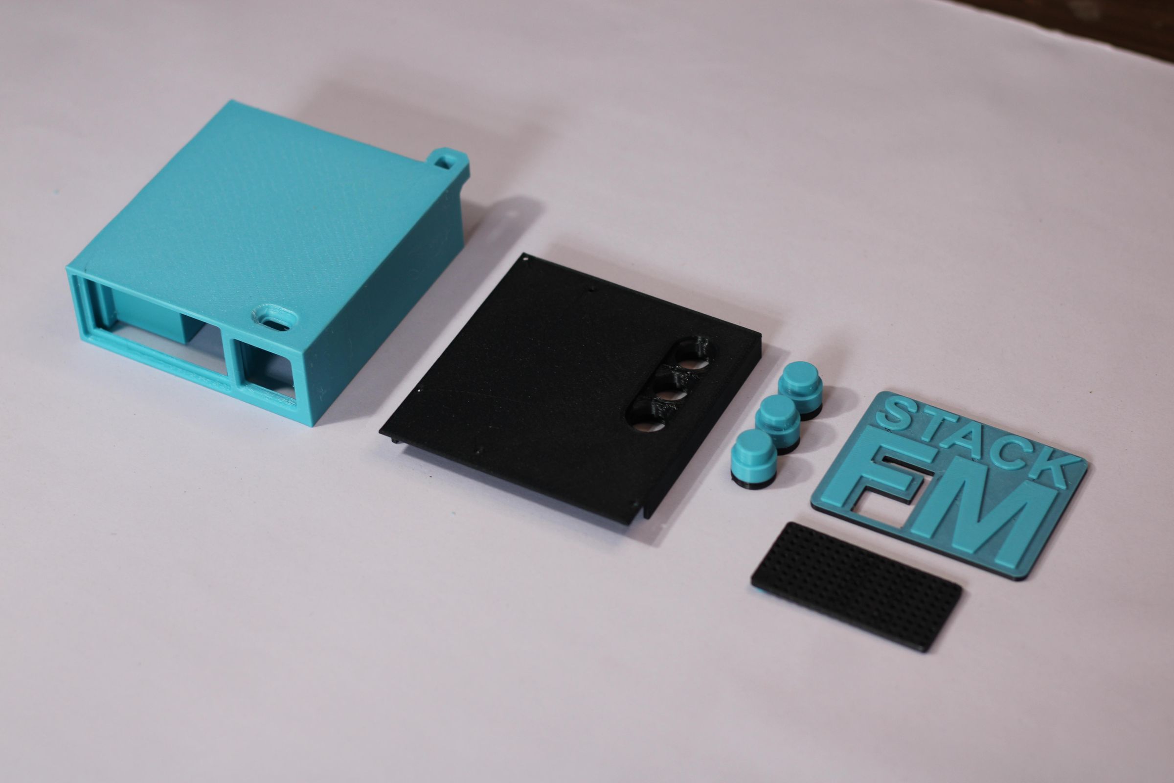
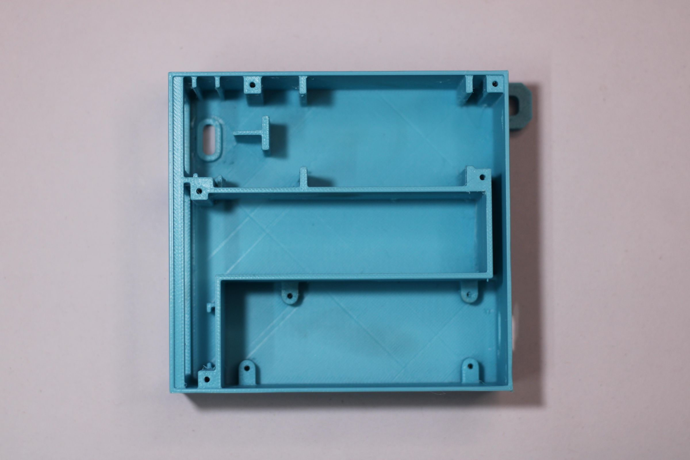
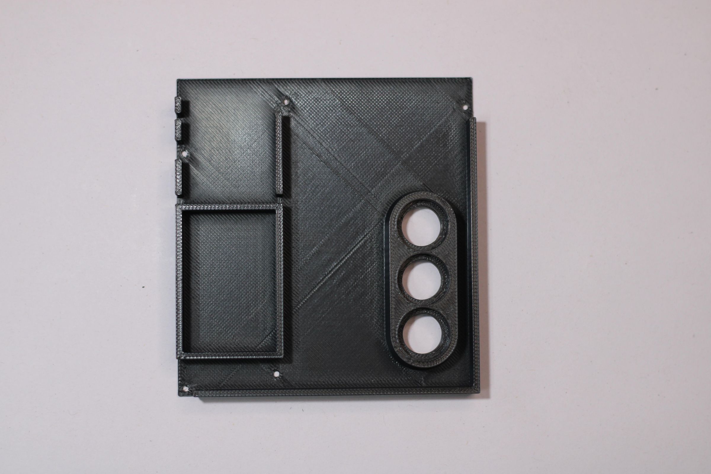
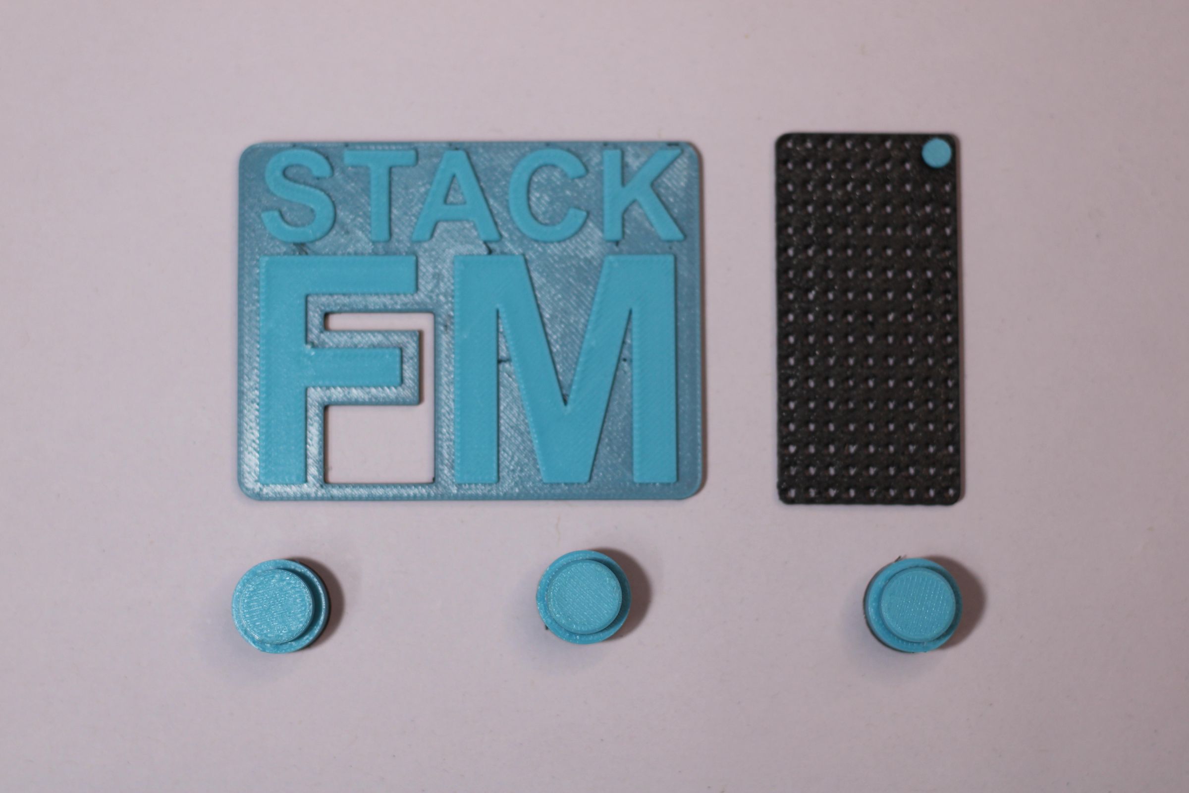
Once the design was finalized, I moved on to 3D printing all the enclosure parts. Instead of printing the whole body as a single piece, I split the design into separate parts so that everything would be easier to print, assemble, and finish.
As you can see in the picture, the main parts include the blue outer enclosure, black front panel, three buttons, raised STACK FM logo, and the speaker grille. Printing these parts separately also made it possible to use different colors without having to deal with complicated post-processing or painting.
The main body was printed in Aqua PLA, which gives the radio its main color. The front panel was printed separately in black so that the controls and the raised logo would have a strong contrast against it.
The STACK FM logo was also printed as a separate raised piece. This makes it stand out from the front panel and gives the enclosure a more finished, almost commercial-product look.
The three circular buttons were printed separately as well. Keeping them as individual parts makes them easier to install and also allows them to move properly when pressed.
I also printed the speaker grille separately. It has a simple pattern of small holes that allows the sound from the internal speaker to pass through while still keeping the speaker protected inside the enclosure.
One of the advantages of designing and printing the enclosure this way was that I could make small changes to individual parts without having to reprint the entire enclosure. It also made it much easier to experiment with the colors and fit of the different components.
PCB DESIGN
.jpg)
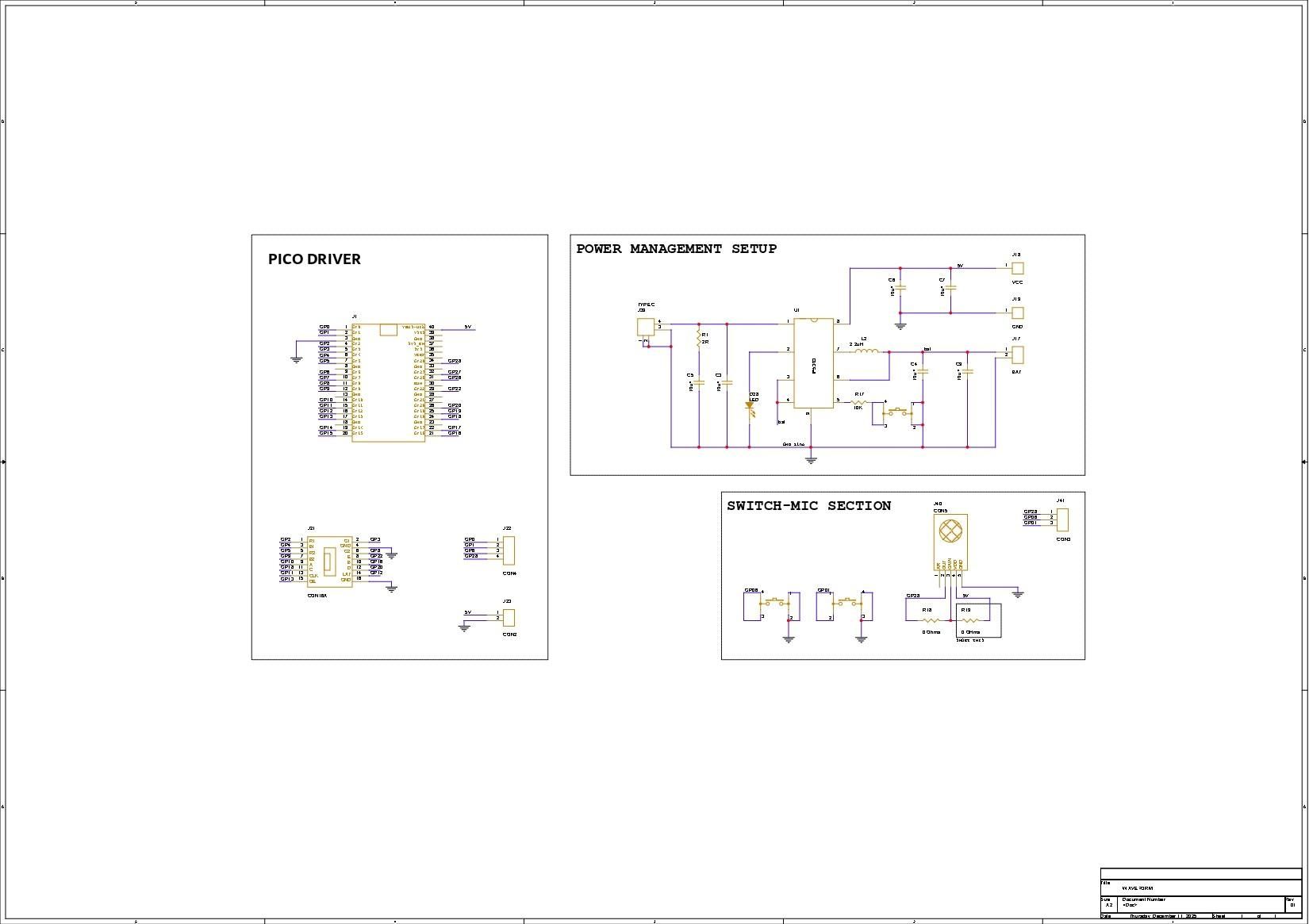
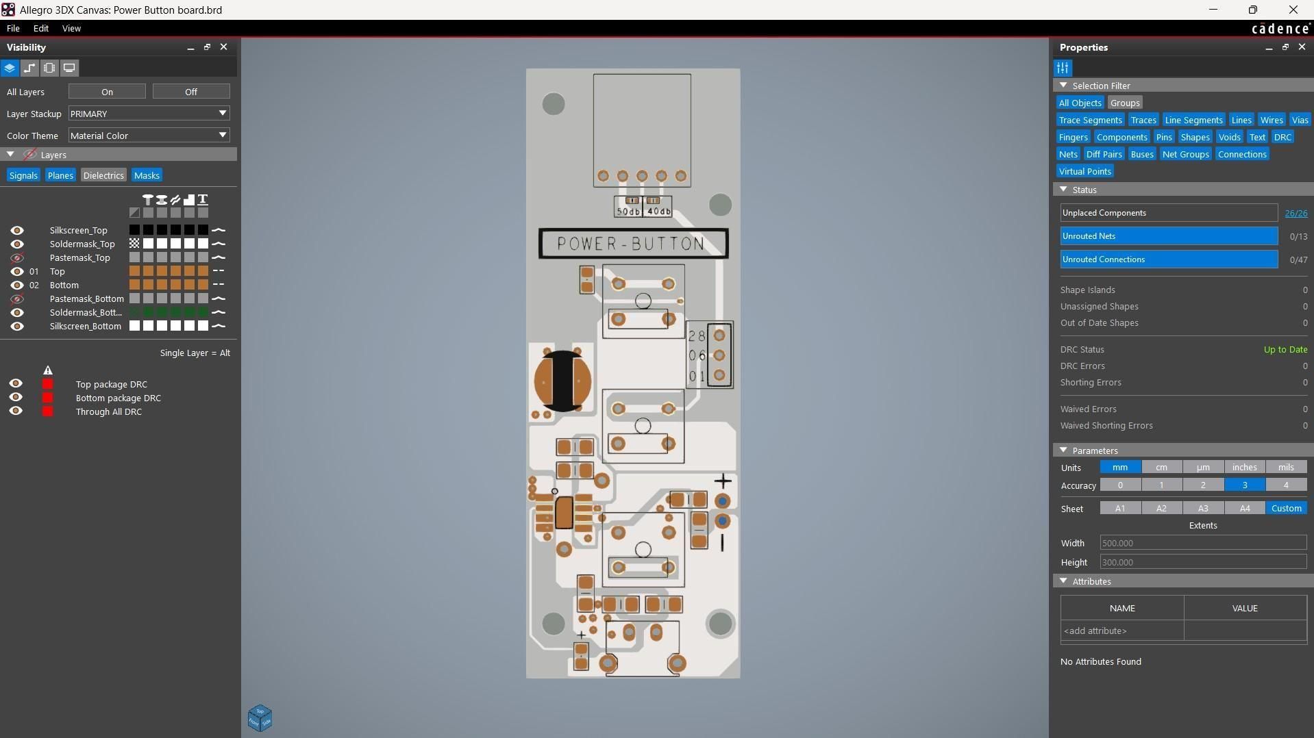
For this project, we used a single custom PCB that combines the push buttons and power-management circuit into one compact board. The PCB was adapted from one of my older Waveform projects, with the microphone section not being used for Stack FM.
The board contains the three push buttons and the IP5306 power-management IC. A Li-Po cell is connected to the IP5306 power-management IC, which provides a stable 5V 2A output to power the matrix and the Pico. The three buttons are used as the physical controls for the project: one is the main power switch connected to the IP5306, while the other two are connected to GPIO0 and GPIO1 of the Pico.
The microphone section from the original Waveform PCB is not used in this project, so the MAX9814 and its connections have been left unused.
We also added the required connectors for interfacing the PCB with the rest of the project. The HUB75 connector (CON-16) is used to connect the 64×32 LED matrix to the Pico, with the connections as follows: A to GPIO19, B to GPIO16, C to GPIO18, D to GPIO20, E to GPIO22, CLK to GPIO11, LAT/STB to GPIO12, OE to GPIO13, R1 to GPIO2, G1 to GPIO3, B1 to GPIO4, R2 to GPIO5, G2 to GPIO8, and B2 to GPIO9.
We also included a CON2 connector for 5V and GND and a CON4 connector breaking out GPIO0, GPIO1, GPIO26, and GPIO28.
The PCB was designed using the PCB outline from our 3D CAD model. This helped us position the push buttons, USB Type-C port, Pico footprint, mounting holes, and connectors correctly according to the dimensions of the enclosure.
PCB ASSEMBLY
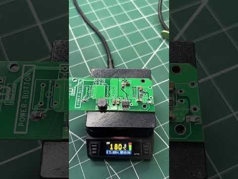
- We have two different circuits in this project. We start with the Switch–MIC–Power board assembly process. Using a solder paste dispensing needle, we apply solder paste (63/37 Sn/Pb) to each SMD component pad.
- Next, we use ESD tweezers to pick and place each SMD component onto the PCB.
- After placement, the PCB is moved onto the reflow hot plate. As the board heats up from below, the temperature gradually rises until it reaches the solder paste’s melting point. Once the PCB reaches around 200°C, the solder paste melts and all the SMD components are secured in place.
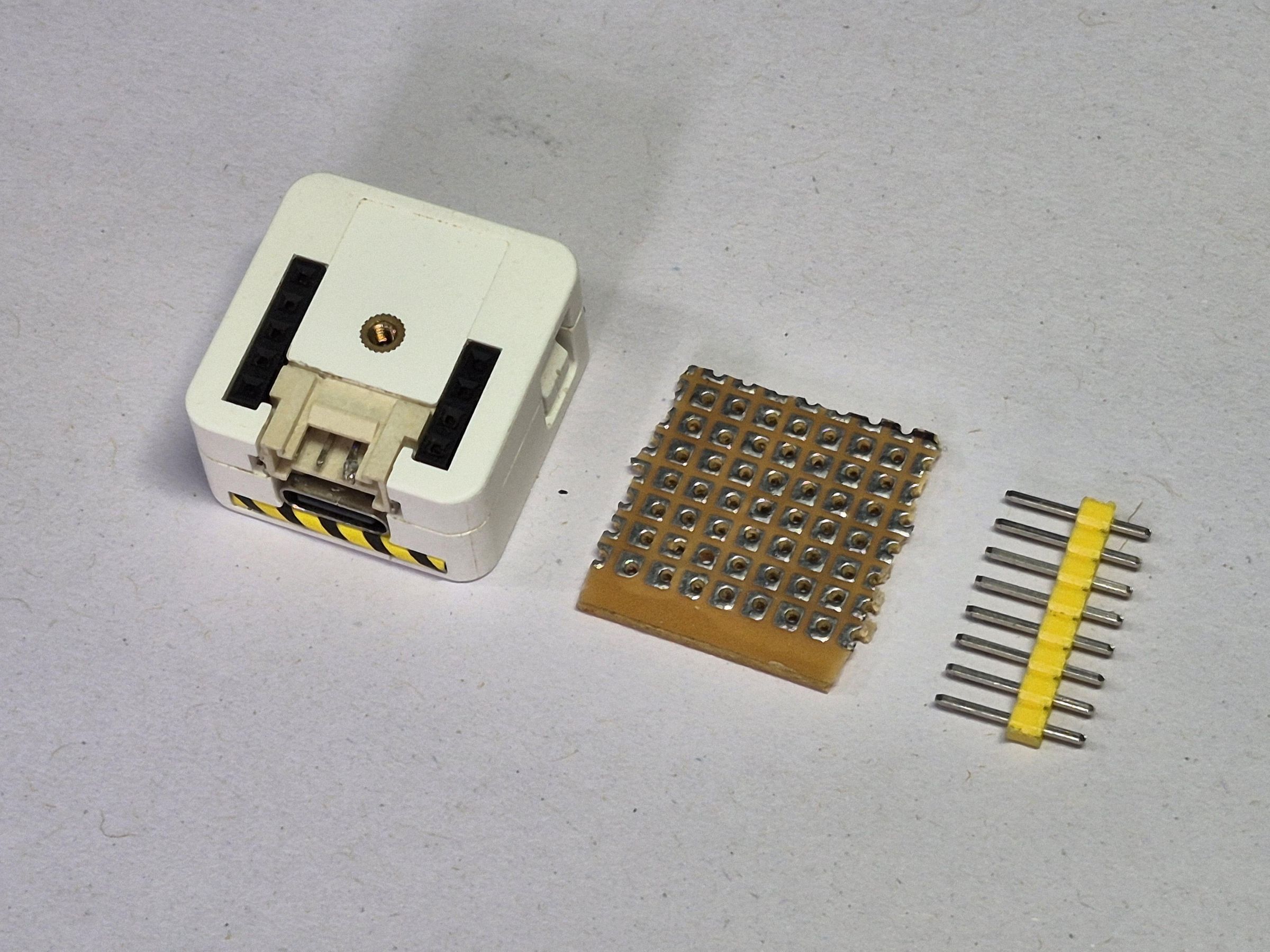
MAKING THE HAT FOR M5 ATOM
.jpg)
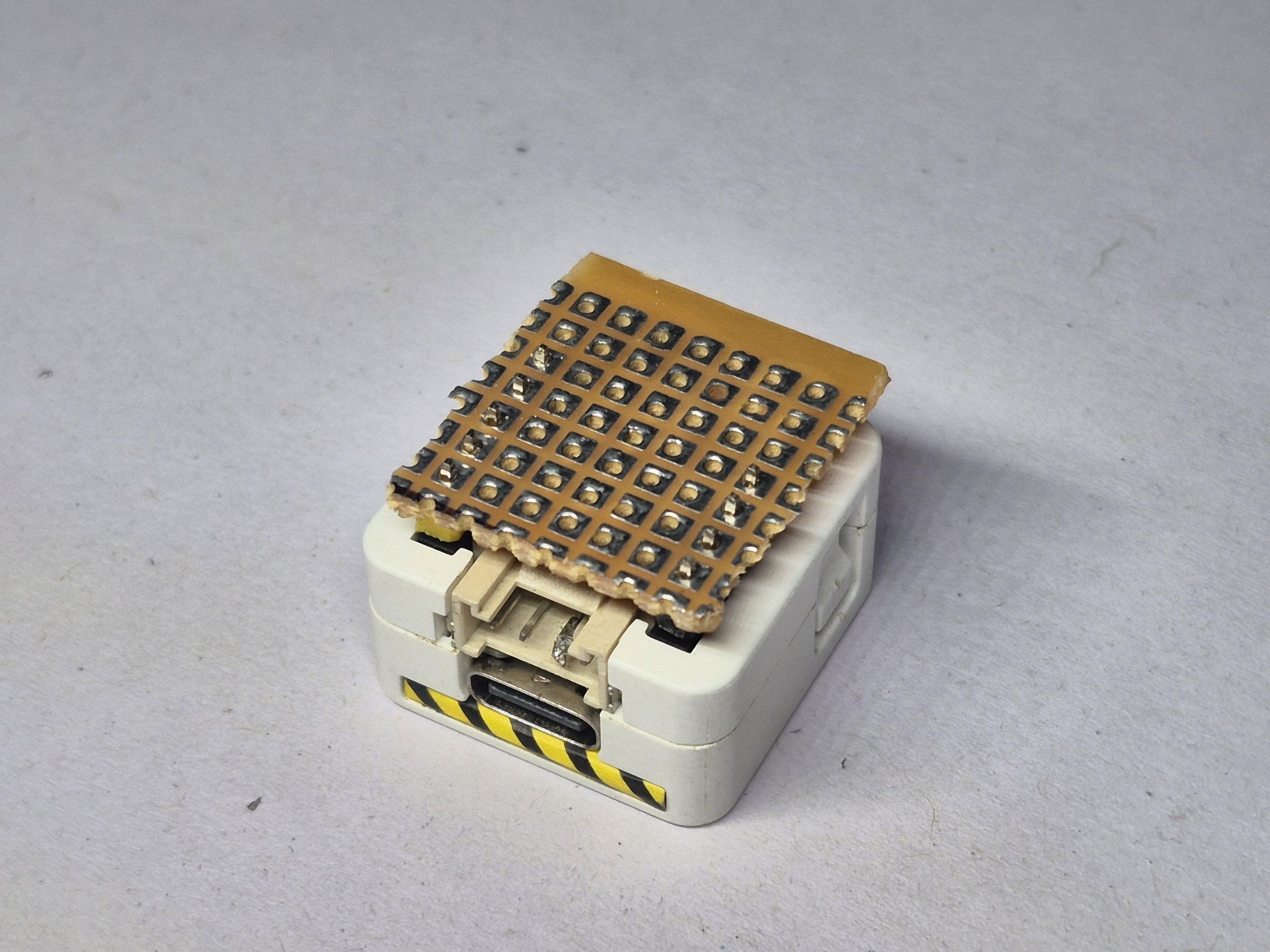
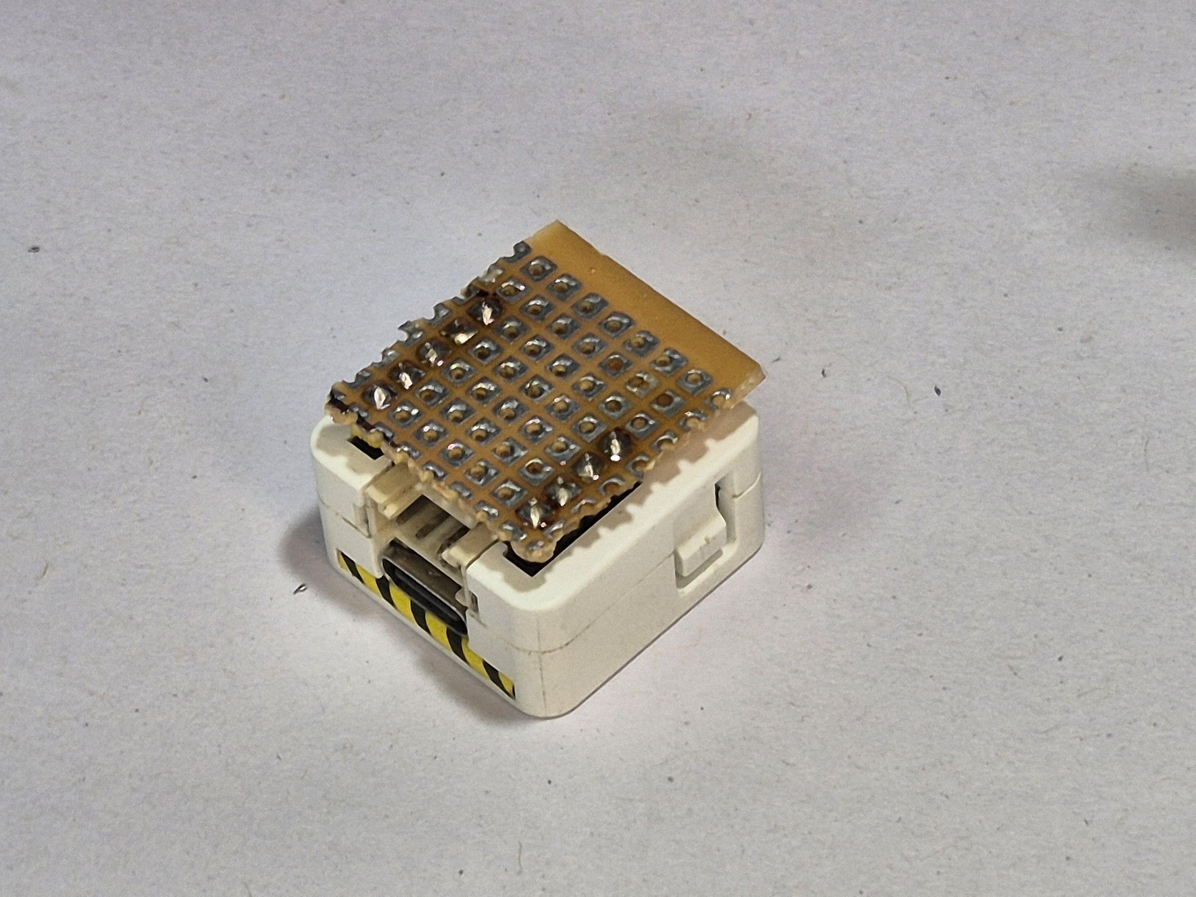
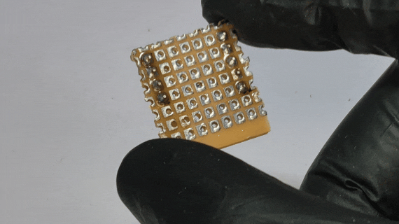
To make the wiring cleaner, I also made a small custom HAT for the M5Stack AtomS3.
The HAT works like a small add-on board that sits with the AtomS3 and carries the basic connections for the MAX98357A module, speaker wiring, and external buttons. Instead of keeping everything loose with jumper wires, the HAT makes the final setup more compact and reliable.
For this board, the connections were routed according to the pins used in the code. The MAX98357A I2S lines were connected to the selected GPIO pins, and the two external buttons were connected to their assigned pins with ground.
This HAT was then attached with the AtomS3, making the complete electronics section easier to fit inside the 3D printed body.
After this, the final assembly became much cleaner, and the device was ready to be placed inside the enclosure.
CIRCUIT AND WIRING
The speaker is connected directly across SPK+ and SPK-.
Before powering the circuit, I checked the 5V and ground connections, verified the three I2S wires, and made sure neither speaker terminal was connected to ground.
BREADBOARD SETUP
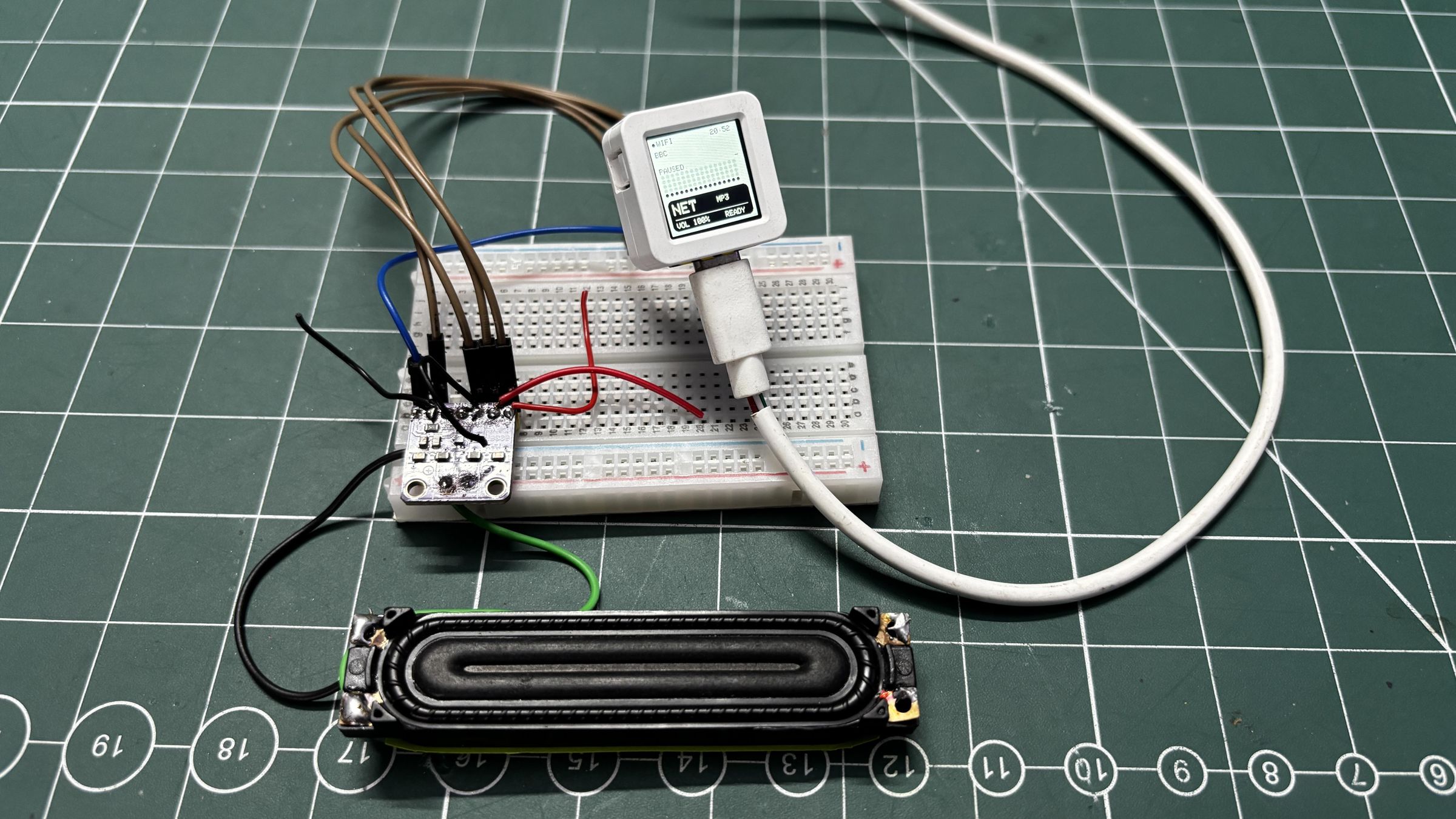
Before placing everything inside the 3D printed body, I first tested the whole circuit on a breadboard.
This step was important because the project had multiple parts working together: the AtomS3, the MAX98357A amplifier, the speaker, and the physical buttons. Testing everything outside the enclosure made it much easier to check the wiring and fix any issue before final assembly.
I connected the MAX98357A module to the AtomS3 using the I2S pins. The speaker was connected to the output terminals of the MAX98357A module.
After this, I added the push buttons on the breadboard and connected them to the GPIO pins. The buttons were wired in a simple way, where pressing the button connects the GPIO pin to GND. The code uses internal pullups, so no extra pullup resistors were required.
Once the wiring was complete, I uploaded the first test code to the AtomS3 and checked whether the device was connecting to Wi-Fi and responding to the local web app.
The breadboard setup helped verify the
- MAX98357A audio output
- speaker connection
- I2S wiring
- button input
- Wi-Fi connection
- communication with the local web app.
This also helped confirm that the basic radio system was working before moving everything into the final enclosure.
FINAL CONNECTIONS AND ASSEMBLY
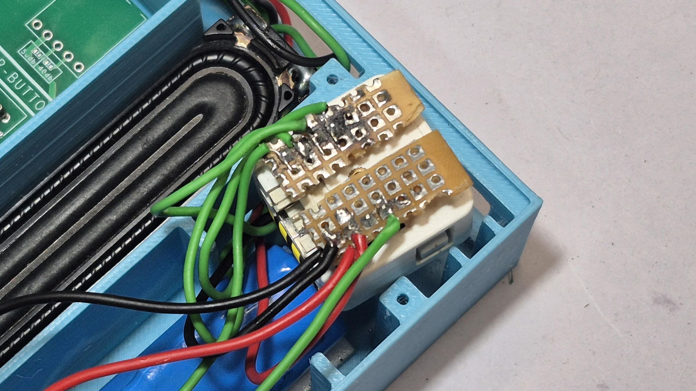
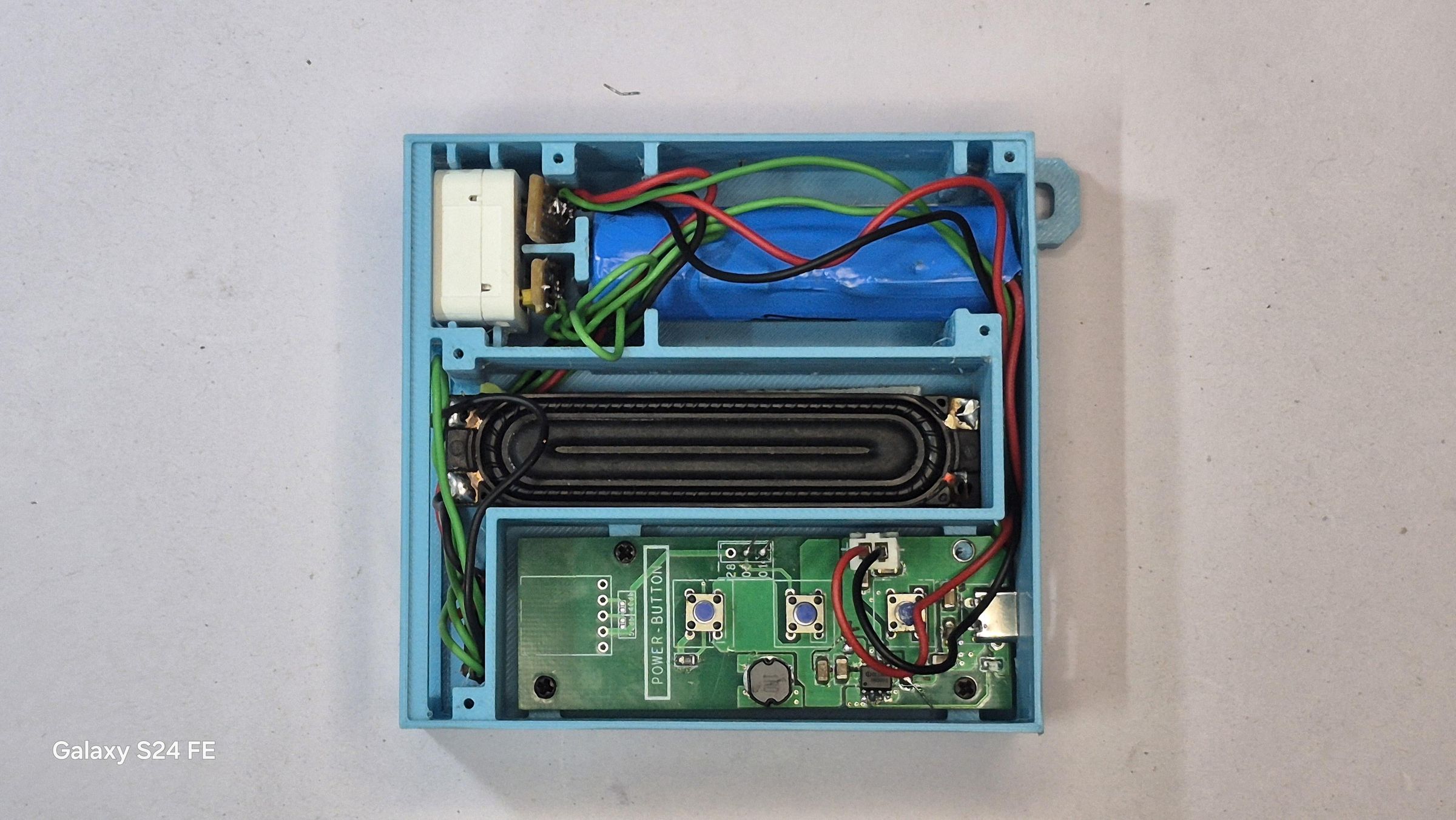
After testing the circuit on the breadboard, I moved on to the final wiring and assembly inside the 3D printed body.
First, I placed the AtomS3 inside the enclosure and checked the screen alignment with the front opening. After this, I positioned the MAX98357A amplifier and the speaker inside the body.
The speaker was placed near the side grille so the sound could come out clearly. This was important because the device had to behave like a proper small radio and not sound blocked from inside the enclosure.
Next, I connected the MAX98357A module permanently to the AtomS3 using the same I2S connections tested earlier:
After that, I installed the three front buttons into their slots. The button caps were placed from the front side, while the actual push buttons were aligned behind them.
For the button wiring, I used the GPIO pins selected in the code:
The buttons use internal pullups, so no extra pullup resistors were required.
Once all the electronics were inside, I checked that no wires were pressing against the speaker cone or blocking the buttons. I also made sure the USB-C port of the AtomS3 was still accessible for programming and power.
Finally, the front panel was fixed in place, and the enclosure was closed.
At this stage, Stack FM had taken its final form: a compact 3D printed radio with a display, physical buttons, and speaker output.
CODE
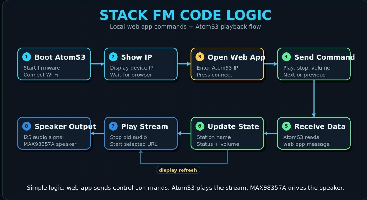
The code for Stack FM is divided into two main parts.
The first part runs on the M5Stack AtomS3, and the second part is the local web app that runs on the phone.
The AtomS3 code handles the hardware side of the project. It connects to Wi-Fi, receives commands from the local web app, sends audio to the MAX98357A amplifier using I2S, updates the display, and reads the physical buttons.
The local web app works as the control interface. It is used to connect to Stack FM using the AtomS3 IP address, select saved items, control playback, and adjust the volume.
So the working flow of the code is:
For the AtomS3 side, I used Arduino IDE along with the M5Unified library and the WebSockets library. The M5Unified library handles the AtomS3 display and button support, while the WebSockets library is used for communication between the local web app and the AtomS3.
The main Arduino sketch is:
The display code is kept separately in:
This keeps the project cleaner because the main sketch handles the working logic, while the display file handles the radio-style screen UI.
The local web app is written in HTML, CSS, and JavaScript:
This file contains the complete radio interface, including the TUNE, SAVED, and DEVICE sections. It also handles the audio selection, saved items, connection, and playback controls.
In the next section, we will go through the AtomS3 code and the local web app code separately.
M5 ATOM Firmware
The main code of Stack FM is written inside the StackFM.ino file.
This file handles the working part of the radio. It connects the AtomS3 to Wi-Fi, starts the WebSocket server, receives audio and control data from the local web app, sends audio to the MAX98357A amplifier, and reads the physical buttons.
The display UI is not written directly inside this main file. I kept the display part separate in DisplayUI.h, which makes the main code easier to understand and modify later.
The main sketch starts by including the required libraries.
Here, WiFi.h is used to connect the AtomS3 to the local network.
WebSocketsServer.h is used so the local web app can send audio and commands to the AtomS3.
M5Unified.h is used for the AtomS3 display and button support.
The I2S driver is used to send audio output to the MAX98357A amplifier.
The Wi-Fi credentials are added at the top of the code.
The MAX98357A pins are also defined in the code
These pins are used for the I2S audio connection between the AtomS3 and the MAX98357A module.
For the physical buttons, I used two GPIO pins
These buttons allow changing the saved items from the device itself.
The code also sets the audio sample rate.
This sample rate is kept the same as the local web app so both sides send and receive audio in the same format.
The WebSocket server is started on port 81.
This is the main communication line between the local web app and Stack FM.
When the web app sends audio data, the AtomS3 receives it as binary data and writes it to the MAX98357A using I2S.
Text commands from the web app are used to update the display state. For example, the web app can send the current media name, playing state, buffering state, or stop state.
The physical buttons are read inside the main loop. When a button is pressed, the AtomS3 sends a command back to the web app.
This lets the physical buttons control the saved list inside the web app.
The main loop keeps everything running.
So in short, StackFM.ino is responsible for:
- Wi-Fi connection
- WebSocket communication
- receiving audio from the local web app
- sending audio to MAX98357A through I2S
- reading physical buttons
- updating the device status
The display design itself is handled separately in the next file, DisplayUI.h
DISPLAY UI CODE
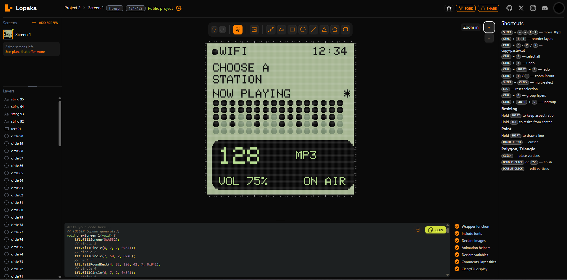
The display UI of Stack FM is written separately in the DisplayUI.h file.
I kept this part separate from the main Arduino sketch so the project would be easier to manage. The main StackFM.ino file handles Wi-Fi, audio, WebSocket communication, and button input, while DisplayUI.h only handles what appears on the AtomS3 screen.
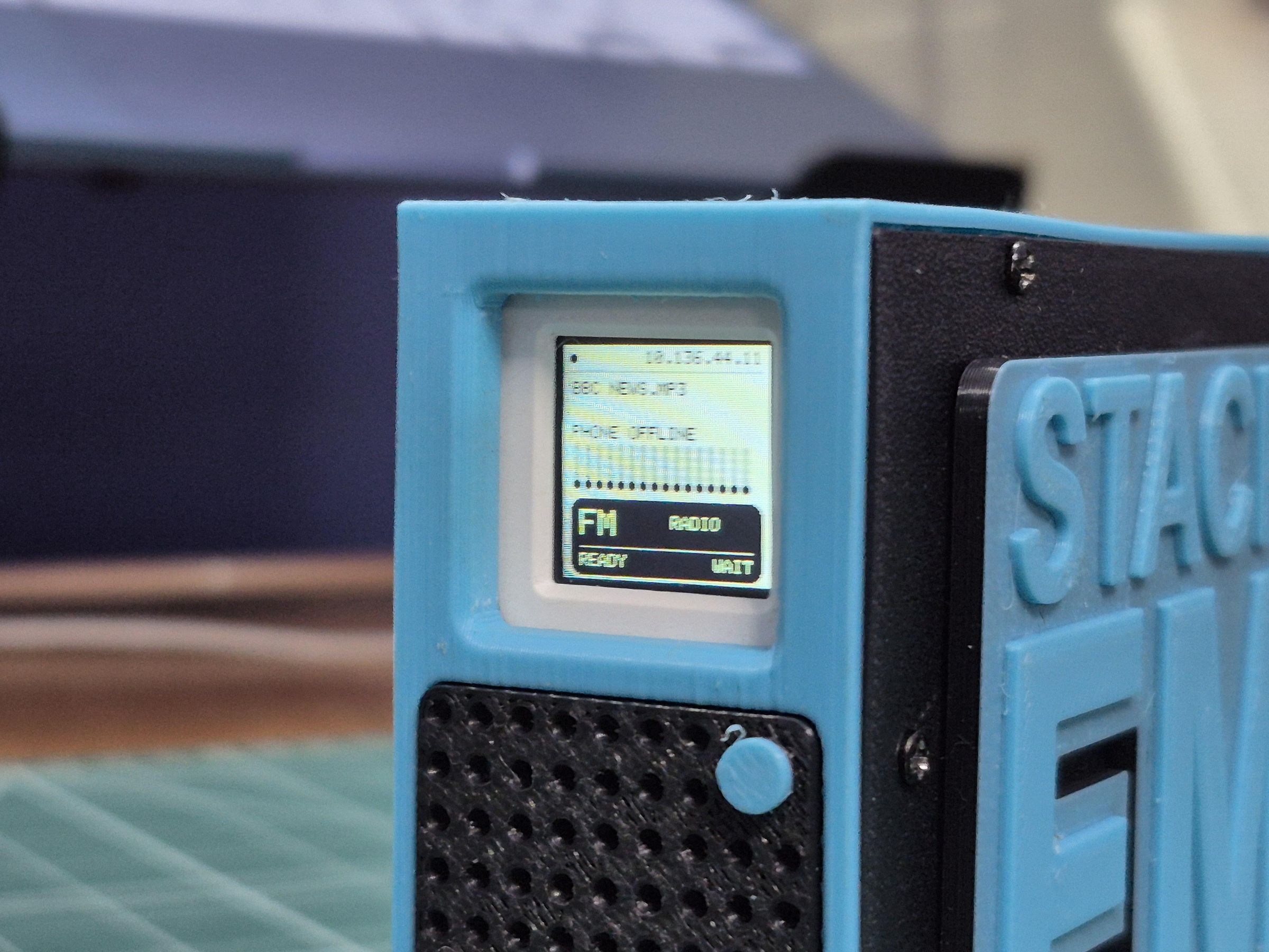
The display UI follows the same visual direction as the physical enclosure and the local web app. It uses a simple radio-style screen with the current media name, connection state, playback status, and a small tuner-like section.
At the top of the display, the device shows whether the radio is ready or offline. It also shows whether the phone/local web app is connected.
The current media or station name is shown in the middle of the screen. Since the AtomS3 screen is small, the text is shortened if the name is too long.
This small function helps keep long names inside the display area.
The main display function is called drawAtomRadioDisplay.
This function updates the complete AtomS3 screen.
Inside this function, I first define the main colors used for the radio UI. These colors match the soft green/black radio-style look used in the project.
The screen is then cleared using the sage color, and the text color is set to black.
At the top of the screen, the display shows the radio connection state.
On the top-right side, it shows whether the phone web app is connected.
The media name is then shown in the center area. If the name is long, it is split into two lines so it remains readable on the small AtomS3 display.
Below the name, the display shows the current state:
A small dot-matrix animation is also added to make the screen feel more alive while audio is playing. The animation is not based on real audio levels, but it gives a nice radio-like visual effect.
The lower section of the screen is drawn as a small tuner block. It shows FM/RADIO and the current playback state.
At the bottom of this block, the display shows whether the radio is on air or ready.
The IP address is also shown on the device display so it can be entered into the local web app.
Overall, DisplayUI.h handles the complete AtomS3 screen layout and keeps the display part separate from the main radio logic.
LOCAL WEB APP CODE
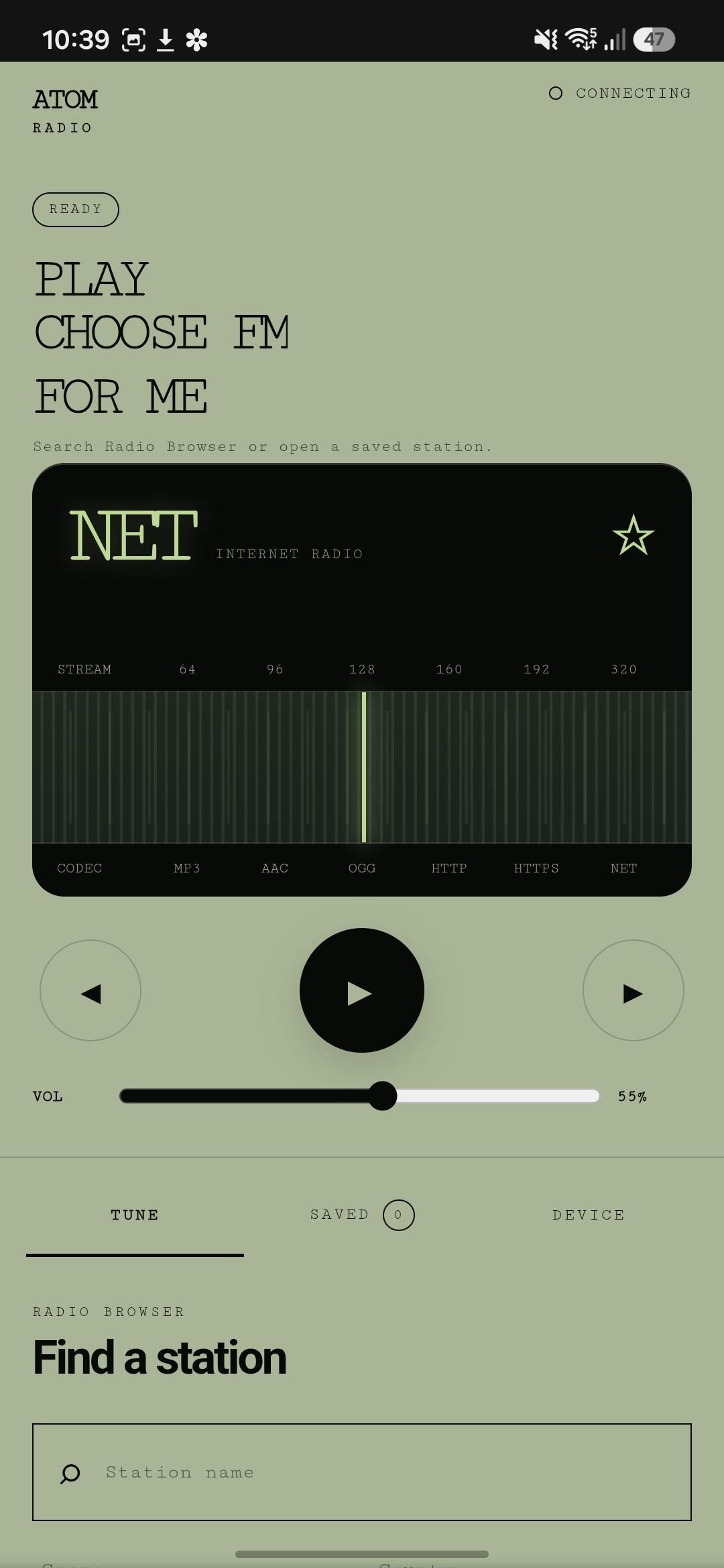
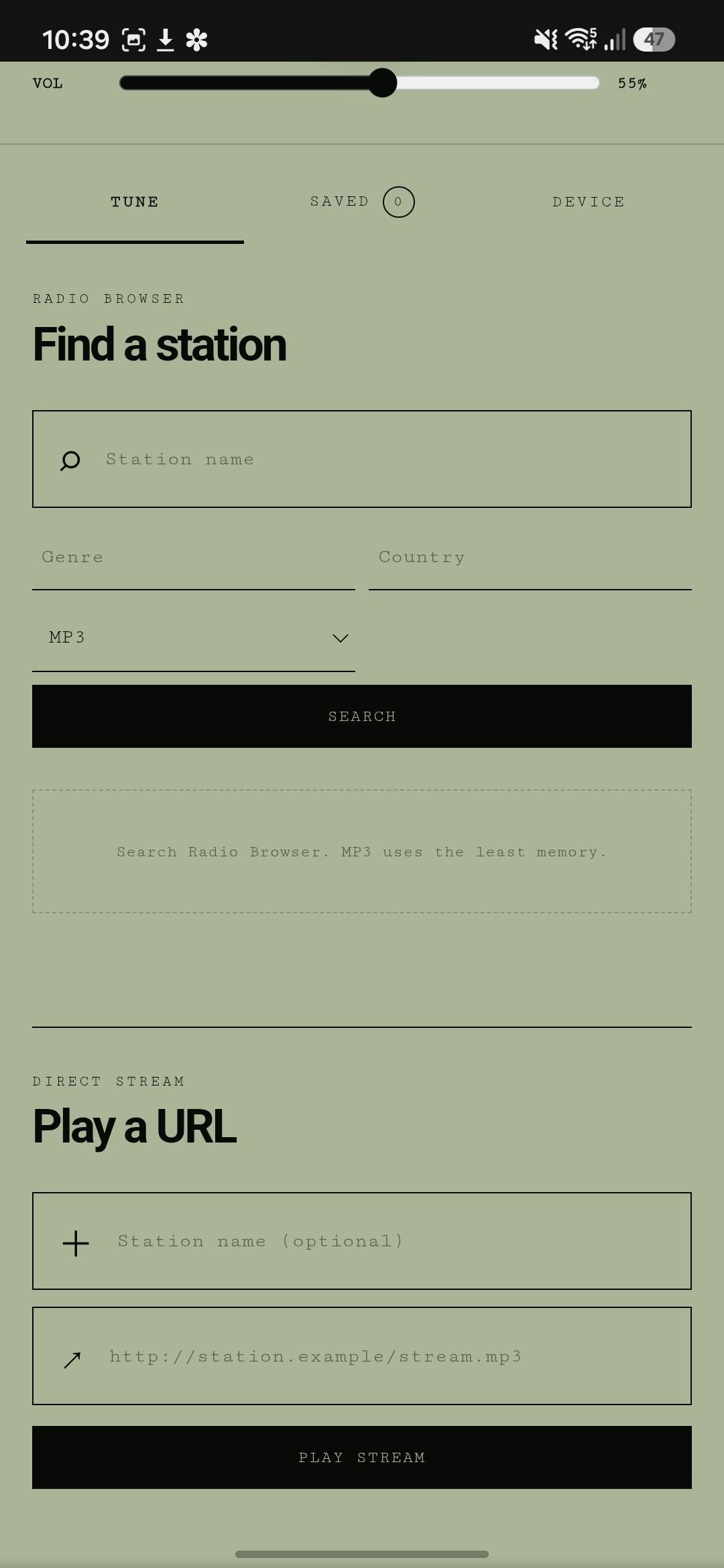
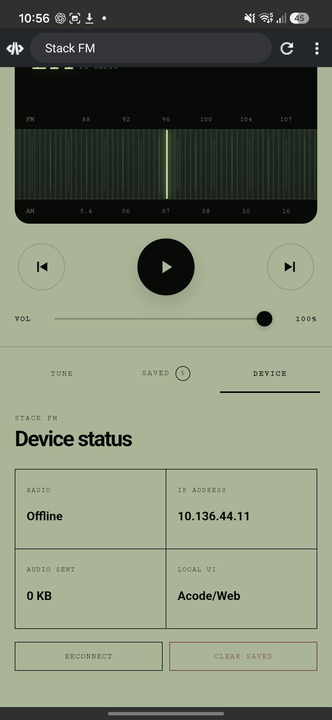
1. Device Connection Logic
This part connects the local web app to the AtomS3.
The user enters the IP address shown on the AtomS3 display. The web app then uses that IP to open a WebSocket connection.
The connection format is:
Port 81 is used because the AtomS3 WebSocket server runs on that port.
2. Saved Media Storage Logic
This section handles the saved media list.
The user can add a media name and audio URL from the web app. Once saved, the data is stored in the browser using localStorage.
Because of this, the saved items remain available even after the page is closed and opened again.
3. Saved List Display Logic
This function displays all saved media items on the web page.
Every saved item is converted into a button. When the user taps that button, the selected media item is played on Stack FM.
4. Play Selected Media Logic
This part sends the selected media URL to the AtomS3.
The web app does not play the sound itself. It only sends the media name and URL to the device.
After receiving this data, the AtomS3 starts playing the selected source through the MAX98357A speaker.
5. Playback Button Logic
This logic is used for buttons like:
When any of these buttons are pressed, the web app sends a command to the AtomS3. The AtomS3 then performs the action on the actual audio output.
6. Volume Control Logic
This part controls the volume of Stack FM.
When the volume slider is moved, the web app sends the new volume value to the AtomS3. The AtomS3 uses this value to change the speaker output level.
7. Common Message Sending Function
This is the common function used by all controls.
Before sending any command, it first checks whether the web app is connected to the AtomS3. If the connection is active, it converts the command into JSON format and sends it to the device.
UPLOADING THE CODE TO ATOMS3
After completing the main ESP32 code and the display UI code, the next step is uploading the firmware to the M5Stack AtomS3.
For this, I used the Arduino IDE. The complete firmware folder contains the main .ino file and the display UI header file in the same sketch folder.
The StackFM.ino file is opened in Arduino IDE, and the DisplayUI.h file stays inside the same folder so that the main code can include it properly.
Before uploading, the required board and libraries need to be installed in Arduino IDE.
The board settings used for uploading are:
After selecting the correct board and COM port, the code is compiled and uploaded to the AtomS3.
Once uploaded, the AtomS3 starts by connecting to the saved Wi-Fi network. After the connection is successful, the display shows the Stack FM interface along with the device IP address on the top-right side.
This IP address is important because it is used in the local web app to connect the browser interface with the radio device.
After this step, the hardware side of Stack FM is ready. The AtomS3 can now receive commands from the local web app and control audio playback through the MAX98357A speaker.
PLAYING MUSIC

To play music, first open the Stack FM local web app and enter the IP address shown on the AtomS3 display.
After connecting, go to the saved section, select a music link, and press play. The AtomS3 receives the command and plays the audio through the MAX98357A speaker.
PLAYING NEWS

To play news, follow the same process. Enter the AtomS3 IP address in the web app, connect the device, select a saved news link, and press play.
The selected news stream is sent to the AtomS3 and played from the speaker.
CONCLUSION
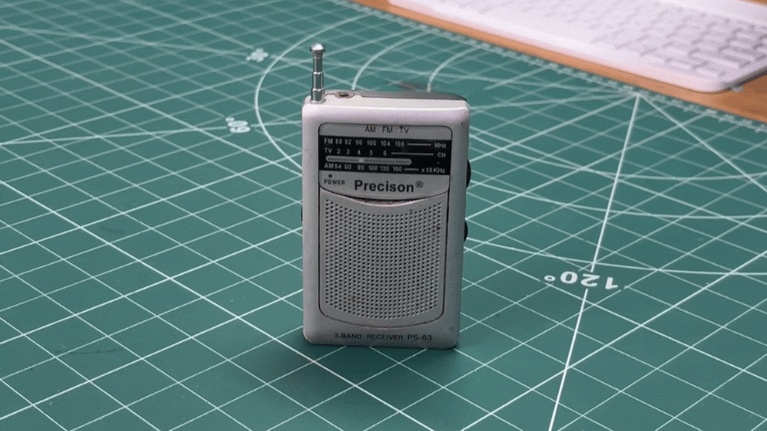
And that’s how Stack FM was completed.
This project started with the idea of making a small FM-style radio using the M5Stack AtomS3, but instead of adding a large screen or complicated controls, I used a local web app as the control panel.
The AtomS3 connects to Wi-Fi, shows its IP address on the display, receives commands from the web app, and plays audio through the MAX98357A speaker. Music and news streams can be selected from the saved list, making it work like a compact desktop radio.
The 3D printed body, front buttons, display UI, and speaker output bring everything together into a finished little radio device.
Overall, this was a fun build and a good way to turn the AtomS3 into a practical radio-style project with both physical hardware and a browser-based interface