Stage Lighting Demo

In this inscrutable we will teach you how to build your own stage lighting demo. This stage lighting demo will allow you to learn how different angle lighting can create different effects on the objects in the stage. The Stage has 12 LED's 4 in front and 4 on each side. The lights can be tilted up and down and each LED can be turned on or off.
Supplies
Link to google sheet BOM
220 ohm Resistor 1/4w (12)
Tact Button Switch (12)
5mm led White (12)
Arduino Mega 2560
Breadboard
Breadboard Jumper Wires (40)
KNex
Hot Glue
String
Carboard Box
BreadBoard Intro

Below is a layout on how the bread board is internally connected. Each colored line is connected to each other.
Prep Resistors


Trim the leads on 12 220 ohm Resistors to 1/4 inch and bend them to 90 Degrees.
Insert Switches


Insert 3 groups of 4 buttons to the circuit board, each lead of the button should be placed in separate rows of the breadboard.
Insert Resistors

Insert one resistor for each switch, one lead of the resistor should be connected to the ground bus and the other lead should be connected to the same row as one of the switch leads.
Wire Buttons to Arduino

Connect wires from the buttons to the Arduino, the first button should connect to pin 22 and the second button will be connected to pin 23 and so forth until pin 34 on the Arduino.
Prep LEDs


Trim your 12 LED's leads to 1/4 inch in length.
Wire LEDS

Connect the large side of the LED to the breadboards ground bus and the other lead of the LED to pin 32 of the Arduino. Repeat this for the next 11 LEDs connecting up to pin 45 on the Arduino.
Create the Stage


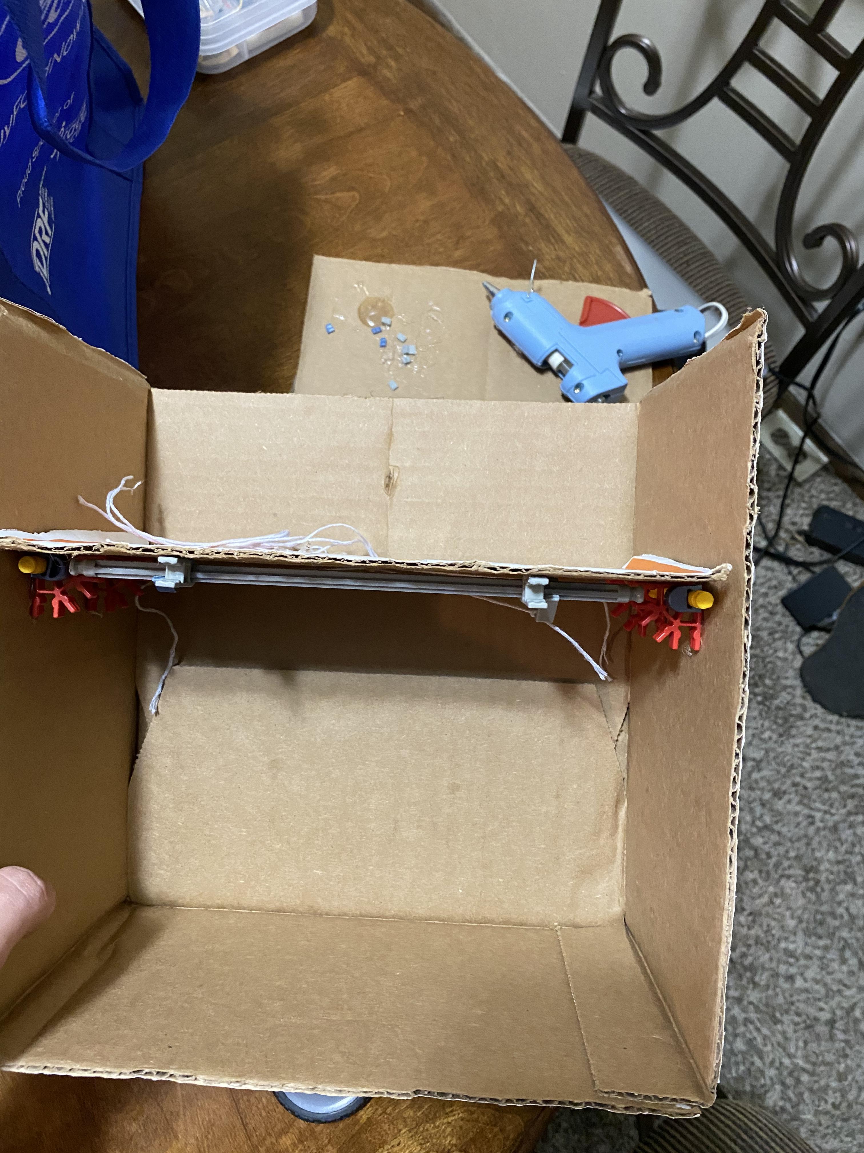
Cut your cardboard box so that you have an open end on one side. Flip the box on its side and cut the top of the box and move it down 4 inches. This will create a top shelf for the Arduino and circuit board to be placed on.
Add Light Fixtures
.jpeg)

.jpeg)
Using hot glue mount red corner KNex pieces into the corners of the box 2 on each side. Add gray pieces to front to put a long KNex piece inside the red and gray pieces so that it can spin. Add strings to the long pieces so that they can move as the strings are pulled.
Add Black Paper


Tape black paper to all exposed edges of the box, this will help make the box look more clean and realistic.
Mount LED's to Fixtures


Glue the gray Knex connectors in the front of the stage and place the last LED fixture into the gray Knex connector.
Code
