Stone Marten Repellent
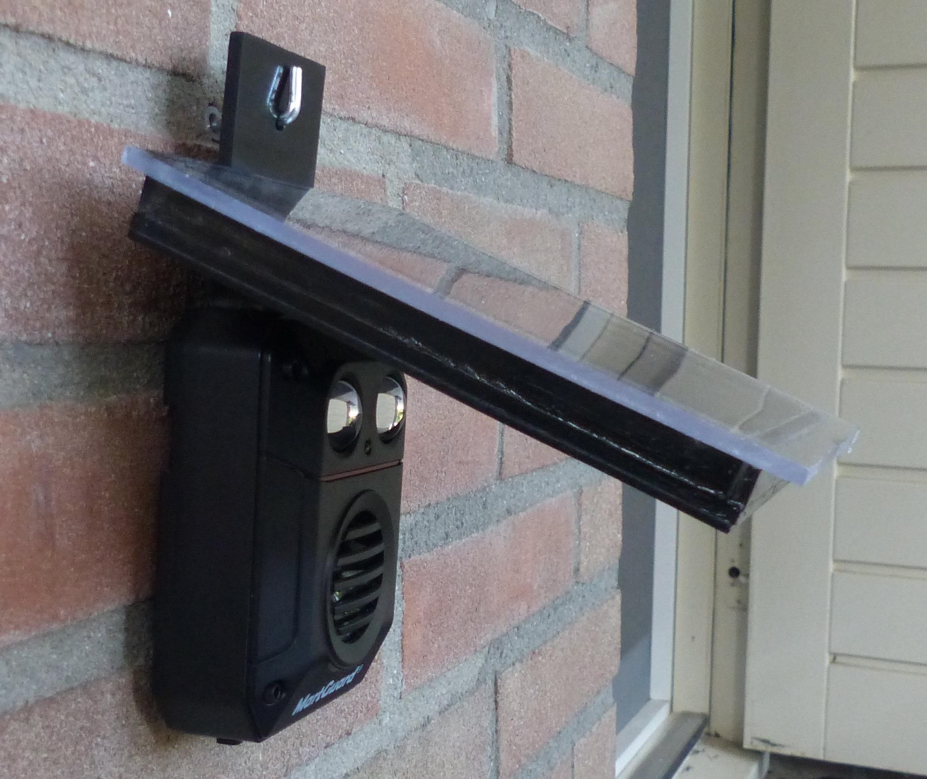
The reason for this project is that I was looking for a battery powered Stone Marten Repellent so I purchased one. I noticed, however, that the batteries did not last very long. After some investigation of this version I found out that it consumed too much power, also when inactive. Besides that I found out that it will not be possible to make a Stone Marten Repellent, with more or less the same functionality, that does not use a lot of batteries during the course of a year.
So I decided to make a Stone Marten Repellent that consumes less power and using a relatively large solar panel to charge rechargeable batteries. In this way it was not needed to replace batteries at all, only after the rechargeable batteries are end-of-life. The reason for using a relatively large solar panel was because the device operates from a location where there is no direct sunlight.
My Stone Marten Repellent is based on a PIC16F15313 Micro Controller that uses an on board Numeric Controlled Oscillator (NCO) to generate an ultrasonic signal in the range of 20 kHz to 50 kHz. That signal then goes to a Piezo Tweeter. And while developing this Repellent I also improved the power output and added some power saving modes.
For the housing I reused the housing of the purchased Stone Marten Repellent and glued the solar panel op top of that. First I did some analyses of the purchased Repellent.
Supplies
You need the following electronic components for this project:
- 1 PIC Micro controller 16F15313
- 1 74HC14
- 1 Schottky Diode 1N5817
- 1 Piezo Tweeter PW3825
- 2 ceramic capacitors of 100 nF
- Resistors, 1 * 22k, 2 * 10k, 2 * 4k7, 1 * 330 Ohm
- 2 resistor of 22 kOhm
- 1 resistor of 22 kOhm
- 1 Green LED
- 4 NiMH AA rechargeable batteries, type ‘Always Ready’
- 1 solar panel of 7 Volt, 120 mA
Some Analysis
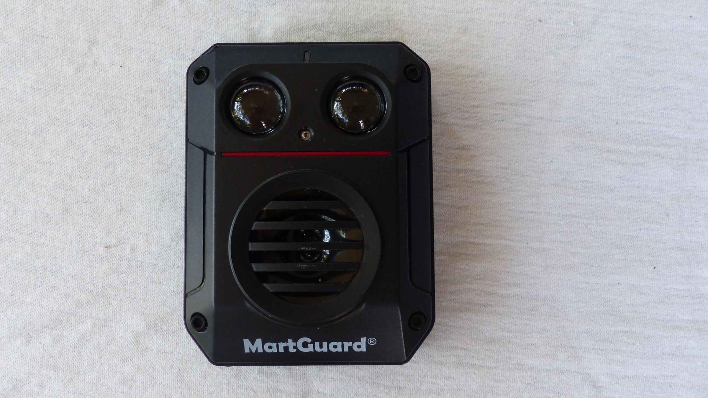
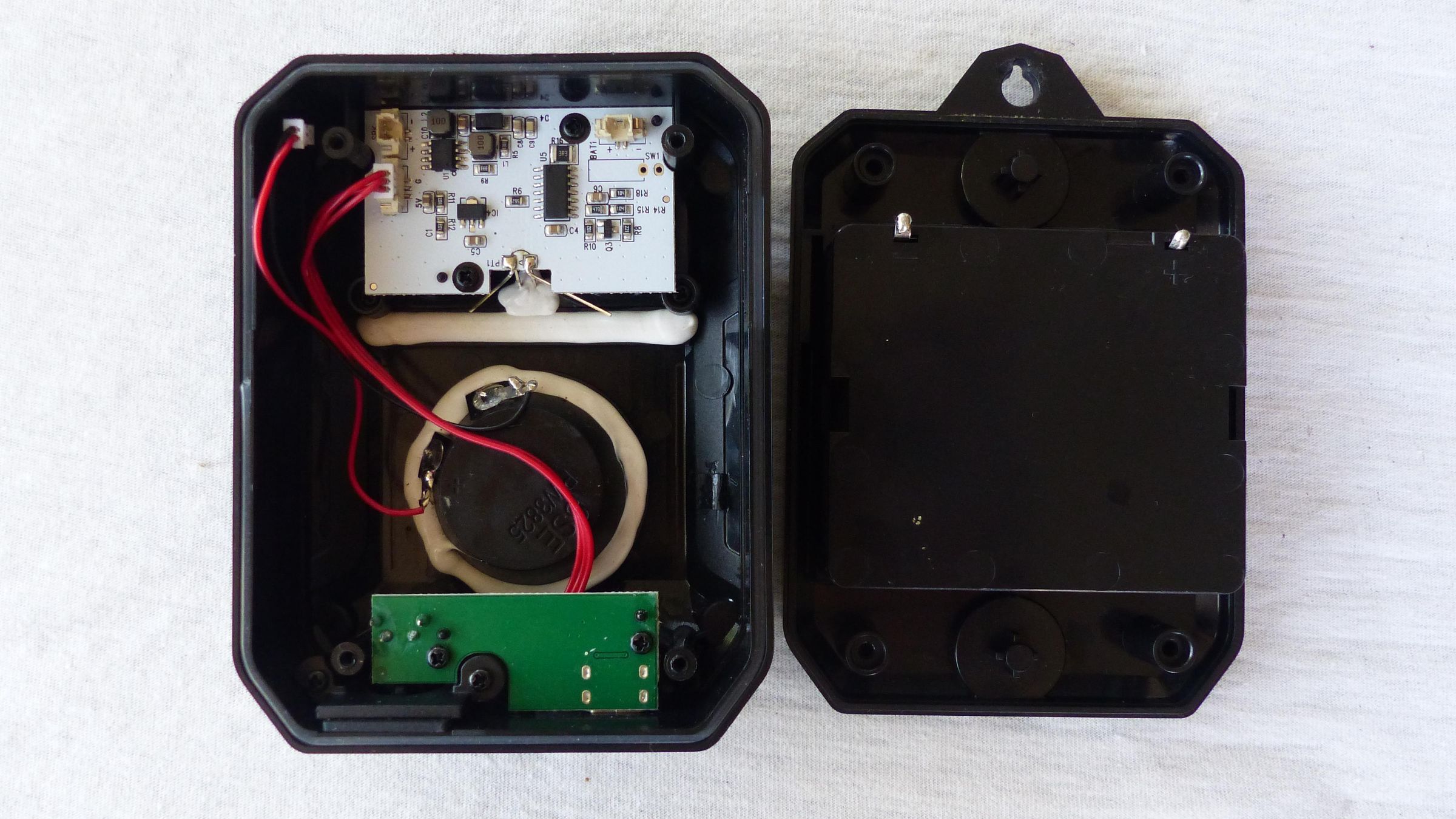
The pictures show the purchased Stone Marten Repellent, the front view and the – open – back view. The Repellent operates using four AA batteries of 1.5 Volt each.
This Stone Marten Repellent has the following specification:
- Operates at 5 Volt (external) or four AA batteries, so 6 Volt.
- Uses a frequency range of 15 kHz – 55 kHz
- Starts at 15 kHz and increases to 55 kHz (sweep tone)
- Does this a random number of times, between 3 times and 7 times
- Repeats this every 2 minutes
- Uses a Piezo Tweeter
- Water resistant housing IP65
- Uses LEDs for generation light flashes, which can be switched off
The reason for using a changing frequency and a random number of repetitions is to prevent that a Stone Marten gets used to the sound pattern. That seems to happen if the sound pattern is always the same.
I performed some measurements on this purchased version and also had a look at the signal on Piezo Tweeter. These are the results without the flashing LEDs:
- Measurements done at 6 Volt (4 AA batteries)
- Power LED is continuously on and consumes 2.4 mA, also when device is idle
- When active, consumes around 10 mA average (without flashing LEDs)
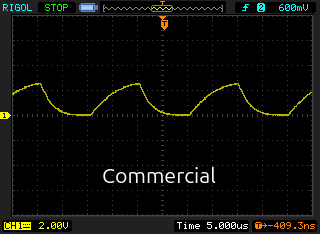
- Signal on the Piezo Tweeter is 2.3 Volt peak to peak
The signal on the Piezo Tweeter is as shown in the screenshot of the oscilloscope. As can be seen the voltage swing is not that large even when using a supply voltage of 6.0 Volt.
The New Design
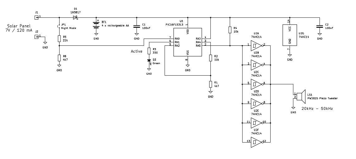
I created a new design using a PIC Micro Controller, programmed with the JAL programming language. The design properties are:
- Built around a PIC16F15313 Micro Controller
- Using a 74HC14 as output buffer for higher audio output
- No flashing LEDs
- Using rechargeable batteries
- Large solar panel, size 11 x 11 cm, 7 Volt 120 mA
- Auto power save
- Option for night mode
- LED indicates activity and operating mode
The picture shows the schematic diagram.
With jumper JP1, the night mode can be selected. In order to reduce power consumption the measurement of the battery voltage, done using resistors R1 and R2, is controlled by pin RA4 of the PIC. This pin is only activate during the measurement. When the device is inactive, pin RA5 switches to input. Resistor R4 will then pull-up this line so that the signal on the Piezo Tweeter is low during the inactive period.
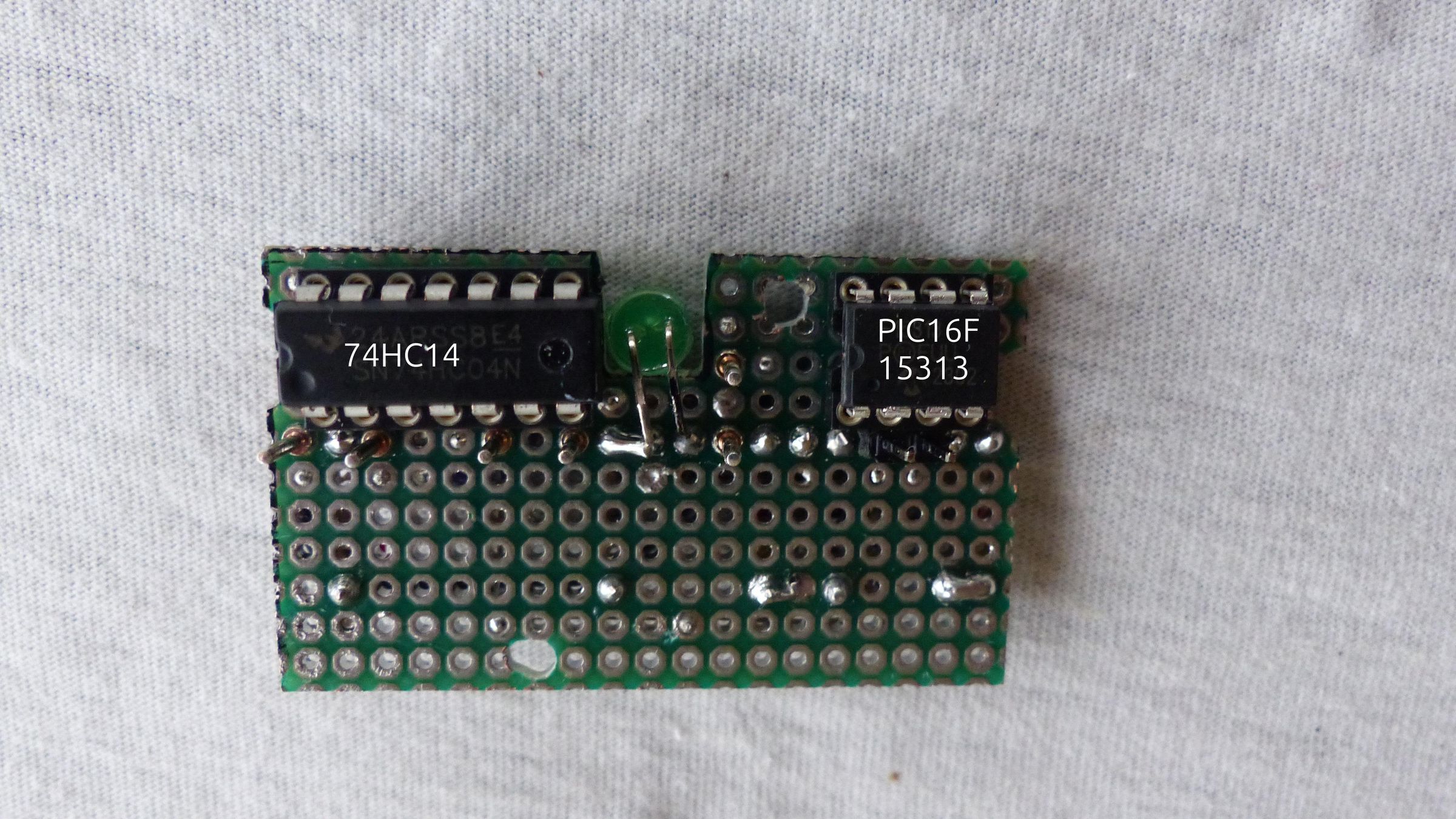
For assembly I used the same board size so that it would fit in the housing of the purchased version.
The New Specification
This new design has the following specification:
- Supports a frequency range between 20 kHz – 50 kHz
- Starts a tone randomly at 20 kHz or at 50 kHz
- Uses randomly two different sweep speeds
- Sweep time is 1 second or 2 seconds for one sweep. Since the sweep goes from one frequency to the other and back again, the total sweep time per cycle is 2 or 4 seconds.
- Does this a random number of times, between 3 times and 7 times
- Repeats 1 minute or 2 minutes (random in normal operation) or after 4 minutes (fixed in power save and power low)
- Uses a Piezo Tweeter
- In direct sunlight the solar panel supplies a 150 mA charging current
- LED blinks indicate operating mode: Normal (3), power save (2), power low (1)
In this design I had chosen for some more random patterns than the original version, like not always starting with the lowest tone and also changing the speed in which the tone goes from low to high or the other way around. Next to that, the cycle repeats – in normal operation - after 1 minute or 2 minutes which is also random.
The power saving modes, are indicated by the LED:
- In normal operation mode the LED blinks 3 times before it starts the random sound patterns. The pattern repeats after 1 minute or 2 minutes.
- If the battery voltage drops below 4.4 Volt (so 1.1 Volt per battery) the device switches to a low power mode. In this mode the pattern does not repeat after 1 minute or 2 minutes but it repeats after 4 minutes and the LED will blink 2 times.
- If the battery voltage drops below 3.6 Volt (so 0.9 Volt per battery) the batteries are empty. The LED will still blink one time every 4 minutes but no sound is produced.
- On the board there is a jumper JP1 that can be placed to activate the night mode. This means that when the Solar Panel voltage drops below 2.0 Volt, the device will start the operation as mentioned above but as soon as the solar panel voltage rises above 2.0 Volt it will stop operating. So the device will recharge during the day but will operate only during the night. During day-time the LED will not blink.
Some New Measurements
I obtained the following measurements:
- Measurements done at 5 Volt (4 AA rechargeable batteries)
- When inactive, consumes 25 uA
- When active, consumes around 15 mA
- Signal on Piezo Tweeter 5 Volt peak to peak
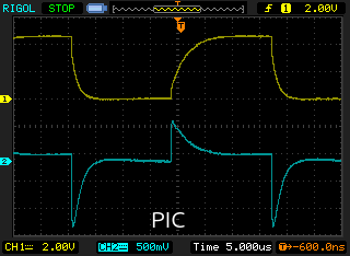
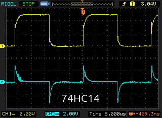
I measured the signal on the Piezo Tweeter when the PIC was directly connected to the Piezo Tweeter and when the Piezo Tweeter was connected to the 74HC14, see the screenshots from the oscilloscope.
The yellow signal shows the signal on the Piezo Tweeter. As can be seen, the curves in the right picture are more steep. Next to that I added a 10 Ohm resistor in series with the Piezo Tweeter to measure the current, which is shown by the blue signal that shows the voltage of this resistor. As can be seen, the current through the Piezo Tweeter is much higher when using the 74HC14. Note that in both pictures, the scale of the blue signal is different, 500 mV (PIC) versus 2 Volt (74HC04).
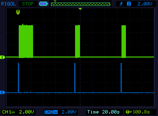
The other screenshot shows the active period and the repetition. The yellow signal shows the signal for the Piezo Tweeter. As can be seen the active period varies due to number of repeats and the duration of one sweep. The blue signal shows the signal for the LED and is used as trigger. The picture also shows that the time between two periods which varies. After the first trigger, the next period starts after two minutes while the next period after that starts after one minute.
The shortest active period is 3 repetitions x 2 seconds = 6 seconds. The longest active period is 7 repetitions x 4 seconds = 28 seconds.
The Software
The software is written in the JAL programming language. Globally it does the following:
- Uses the PIC’s Numeric Controlled Oscillator (NCO) for tone generation
- Sweep tone is created using a Timer interrupt routine running at 2 kHz (0.5 ms) or 4 kHz
- One sweep takes – randomly – one second or two seconds
- Measures the battery voltage using an Analog to Digital Converter (ADC)
- Power save when battery voltage lower than 4.4 Volt
- Power low when battery voltage lower than 3.6 Volt
- Measures the solar panel voltage using the ADC to detect night mode
- Device activate only when solar panel voltage lower than 2.0 Volt
- Goes to sleep when inactive. Device consumes 25 uA in sleep mode
- Wakes up from sleep using the Watch Dog Timer (WDT)
The used Micro Controller has 2k of Flash memory (ROM) and 256 bytes of RAM. The program uses 640 bytes of Flash memory and 46 bytes of RAM.
The JAL program file and the HEX file for programming the PIC are attached. If you are interested in using the PIC Micro Controller with JAL visit the JAL website.
The Housing
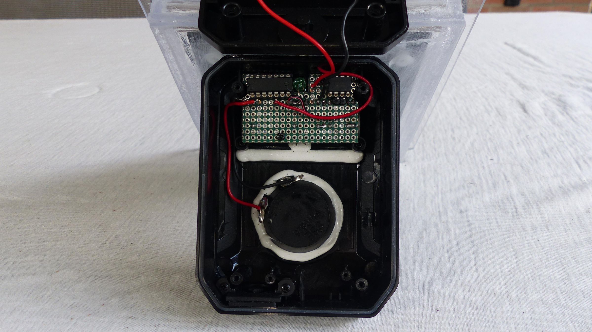
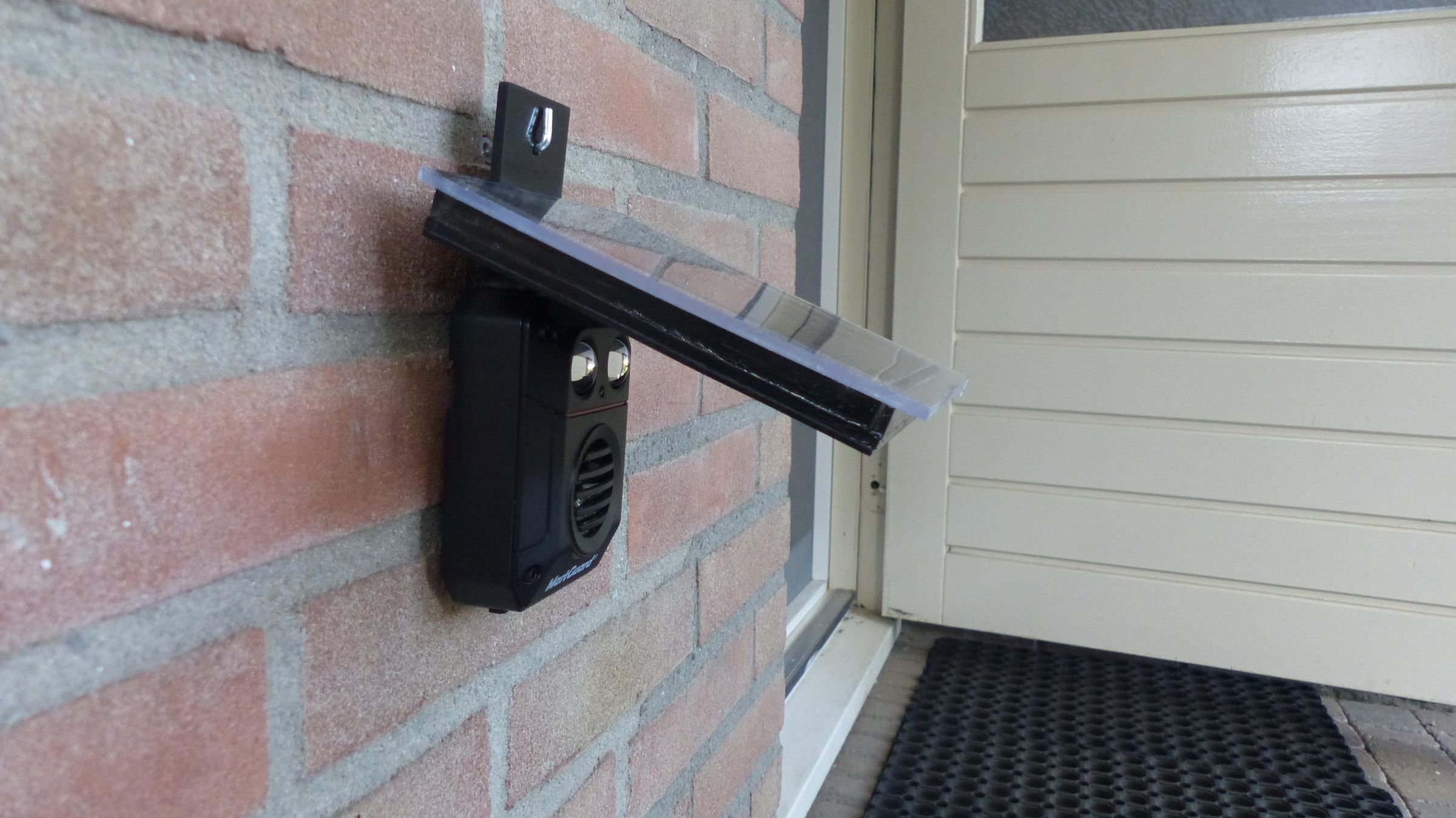
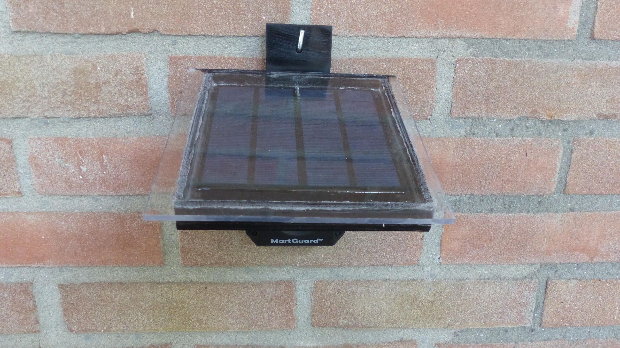
The housing is implemented as follows:
- Using the housing of the commercial Stone Marten Repellent
- Housing is water resistant IP65
- Re-using the Piezo Tweeter
- Board of new design matches the size of commercial version
- PIC16F15313 and 74HC14 mounted at the top of the board
- All other components mounted at the back of the board
- Plastic solar panel construction glued on top of the housing
- Plastic transparent cover mounted on top of the solar panel
The following picture show the board assembled in the housing.
The other pictures show the assembled result. Note that the solar panel is mounted under an angle so that it catches more sun light. You also see how large the solar panel is compared to the housing.
The Device in Action
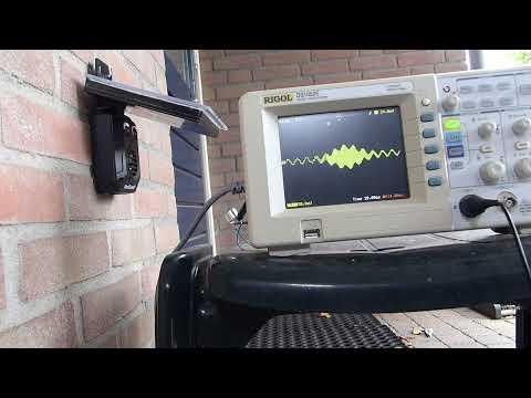
In the video I made the ultrasonic sound visible using an ultrasonic receiver of 40 kHz and an oscilloscope. The receiver is only sensitive in a very narrow 40 kHz range so you will only see a part of the 20 kHz – 50 kHz signal.
The video contains two recordings. The second recording uses a slightly different angle. Here you can see the LED blink 3 times before it starts. When it starts you can also hear a click coming from the Piezo Tweeter.
Additional Information
I tried to determine if the capacity of the solar panel was sufficient for keeping the Stone Marten Repellent alive without the need to recharge the batteries. This – of course – highly depends on how much sunlight is captured by the solar panel. In my situation the solar panel is not exposed to direct sunlight.
I order to get some idea about what the average consumption of the Stone Marten Repellent is, I ran it in active mode for 24 hours while shining some light on the solar panel using a LED lamp. After a full day of operation it seems that the average current that is needed by the Stone Marten Repellent is around 7 mA. I will know after some time of operation if the solar panel will provide enough power to keep the batteries charged.
Have fun building your Stone Marten Repellent and looking forward to you reactions and results!