Switch Adapting a Rhino Fire Elite NERF Blaster
by NeilBuilds in Circuits > Assistive Tech
261 Views, 0 Favorites, 0 Comments
Switch Adapting a Rhino Fire Elite NERF Blaster


I was approached to switch adapt a NERF blaster for a local school with complex needs. The story was a bit of a heart breaker - the child used to love playing NERF before they were involved in a life changing incident. This project allowed them to continue to enjoy NERF, with the support of others, and bring back a spark of joy.
It's not an elegant adaption as the firing controller is operated from a micro-servo and I've had to power the Arduino externally but it's certainly something that works.
The Rhino Fire Elite NERF Blaster came from eBay but these regularly appear on Facebook Marketplace and I used empty coffee cans as the targets. Looking at the number that I was able to provide as targets - I'm starting to think I may have a problem there.
The Warnings:
• For use at targets only.
• Do not direct at people or animals.
• The dart has an impressive range – test before setting up.
• Turn off at main power switch before stepping in front of blaster.
• In the event of an issue – use main power switch to turn off power to the dart launcher.
Downloads
Supplies

Parts to build
1x Rhino Fire Elite NERF Blaster came from eBay but these regularly appear on Facebook Marketplace and I used empty coffee cans as the target
1x 5V Power bank - Amazon link - chosen as these are on special offer, but any 5V USB powerbank will do.
1xArduino controller - Uno r3 available here for Official Arduino supplier
or
1x Arduino controllers - Uno r3 - AliExpress link - generic (lower price but may require a driver to be installed to work correctly, I also got the cable here too as the ones supplied are data capable)
1x micro-servo these 9G micro-servos worked really well
3mm plywood - 55mm x 50mm piece or you could use 3mm thick plastic or even 3D print this - it's for the micro-servo & switch mount. I used plywood as it's what I had to hand.
1x 3.5mm mono jack socket available here
1x On/ off rocker switch available here
Signal wire - as you see fit (I used multiple lengths) I've used white here but feel free to use whatever colour you prefer - here
Male to female jumper wires - Bitsbox link - these are always useful when building something so you can test as you go.
6x D-cell batteries - the blaster will drain standard batteries very quickly when in use. I suggest these which are expensive for a twin pack but they are rechargeable via USB and will pay for themselves after a few charges.
10x coffee can targets - I use these as I have a number to hand and they have no sharp edges.
Tools to build this:
Good soldering iron starter kit - available here
or a more advanced soldering station with holder that I'm using here
Lead free solder (smaller packs are available) here
Drill - here
20mm diameter hole drill bit - here
8mm diameter drill bit - here
Wire strippers (I use these as they take the work out of wire sizing) - here
Wire cutters - here
Philips head screw driver - hardware shop of choice
Small file to open out the plywood mounting points to give a snug fit.
Pencil - makers choice
Ruler or straight edge
You'll also need a 3.5mm jack button for this which I'll suggest my instructable here as a recommendation.
These links are only suggestions for these supplies mind. I have included a few affiliate links for some supplies but only because they are cheap and effective supplies and I use any funds from this for parts to continue this activity.
Open Up the Blaster


Yes - we're in warranty voiding mode here so you can kiss that goodbye.
There are a lot of screws and plastic sections which have slots and slides that need to go into place for this to fit together correctly at the end so I would count your screws out and back in. Don't forget the screw for the battery box on the bottom as you'll need to remove any batteries while you're working on this.
Be gentle with the housing as there may be screws you've missed.
The insides will look like photo 3 - you're looking for the switch showing in photo 4
Make the Servo Mount and Fit
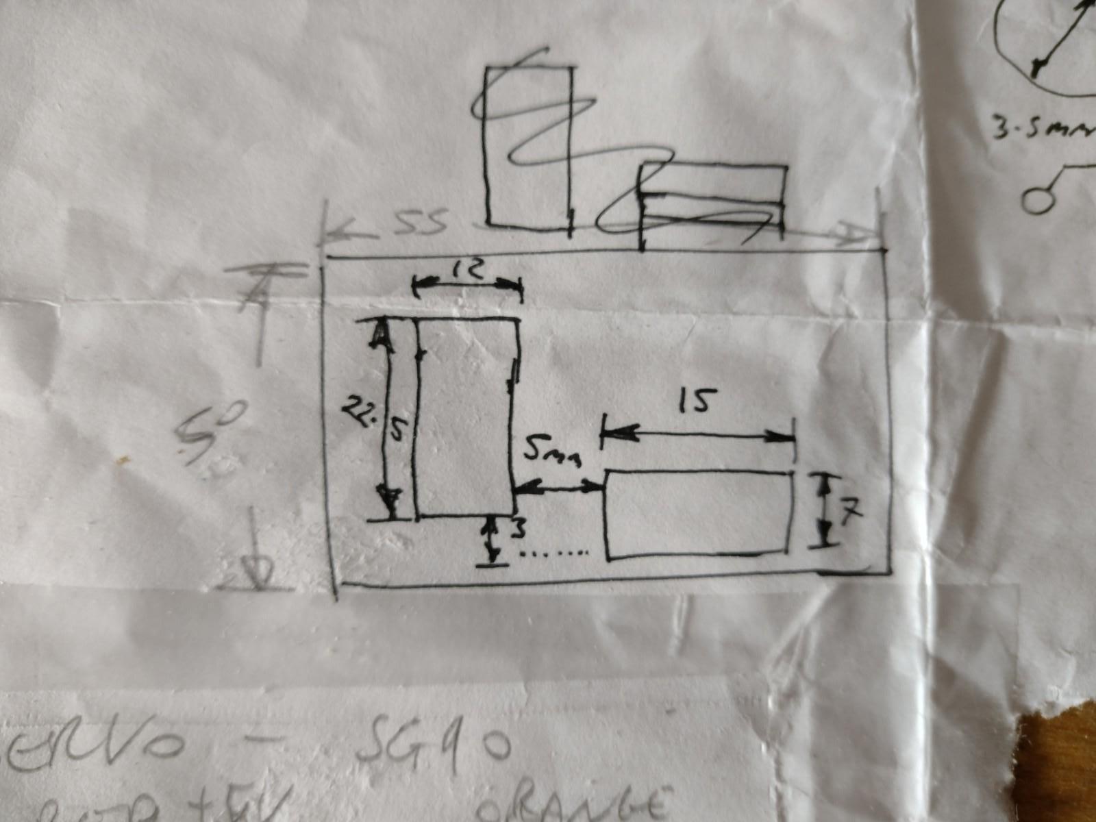
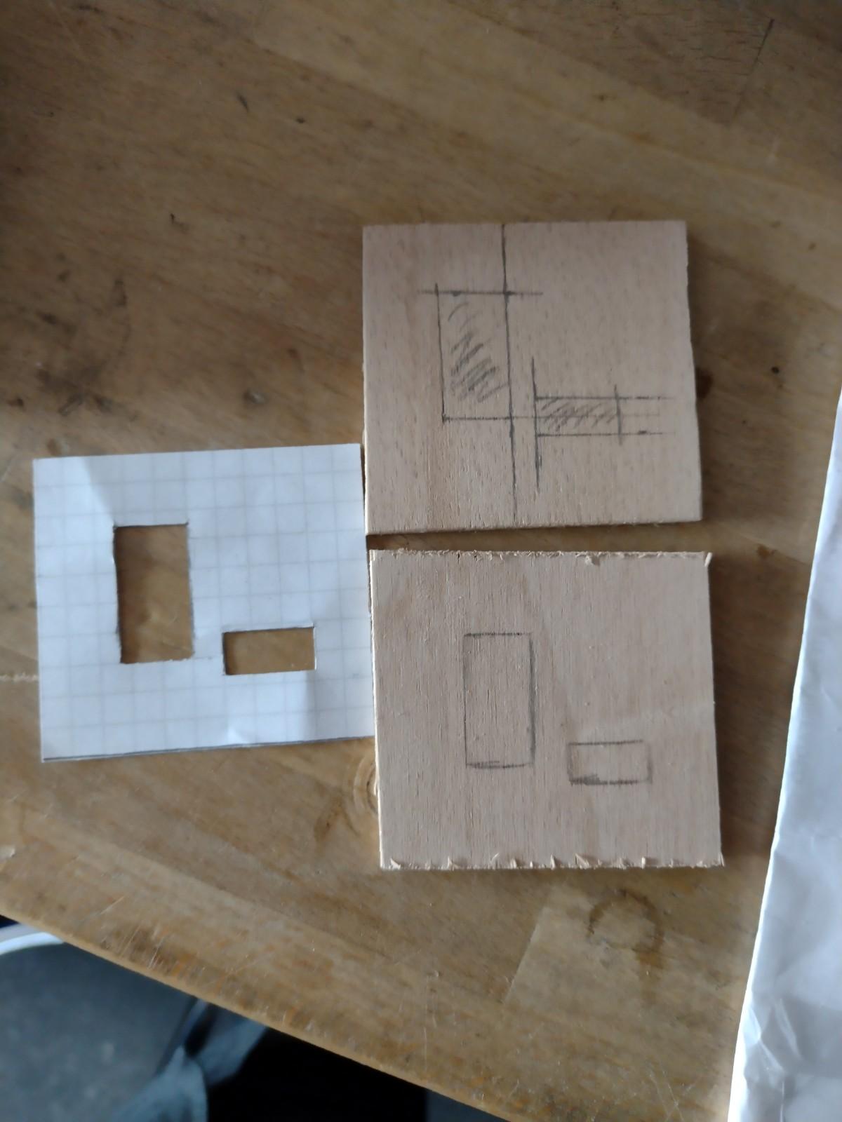


Take your 3mm plywood - 55mm x 50mm piece (or 3mm thick plastic or 3D printed section) mark & cut the slots shown on on the sketch.
These need to be pretty accurate as these holes are for the micro-servo & switch mount as shown in photo 3. Using the linkages that come with the servo, connect them as shown in photo 4 ensuring they move freely. This is how we are going to activate the fire control. Once the switch and servo are mounted and you're happy with their positions, you can move on to the next step.
Servo Wiring Diagram
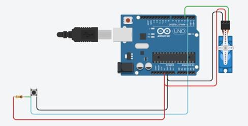


See the attached wiring diagram for the servo operation with the button symbol being the 3.5mm jack socket.
For the 3.5mm you'll want to drill an 8mm hole into the blaster housing at the location shown in photo 2 and a 20mm hole for the main power switch. I found it easiest to solder some lengths of wire to the 3.5mm jack and the power switch before mounting them onto the housing. The power switch cables then interupt the power coming from the D-cell batteries - to create a master on/ off switch for the blaster.
From this point the servo can be connected to the Arduino. The wiring diagram shows the servo directly connected to the Arduino, if you have time it's worthwhile providing the servo with a separate power supply to reduce the load on the Arduino. I added a data capable USB power lead to the Arduino so that I was able to modify the program without having to remove all those screws each time with the lead exiting from the rear of the blaster. This lead will be the power supply to the Arduino from the external power bank.
Now it's time to add the code to the Arduino and to test the servo
Adruino Code & Checks


I uploaded the code to the Ardunio and tested the servo function to ensure everything operated smoothly, you'll be able to see the servo operate and activate the switch. Once testing is completed - the servo mount and Arduino can be secured in place inside the rear of the blaster housing and the blaster re-assembled.
Take care to ensure you're not missing screws or knocking any of the safety switches out of place when reassembling. The hatch on top which is used to remove jammed dart should move freely. There are safety switches on each side of the magazine loading ports which can sometimes not activate correctly if the magazine isn't installed properly.
The designers of this blaster went to great lengths to ensure the safety of this blaster.
Downloads
Bonus Operation


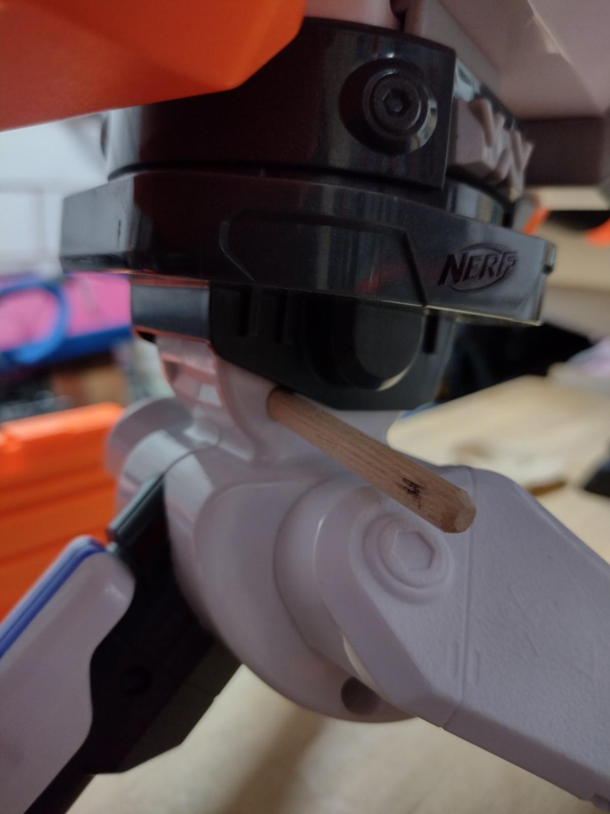
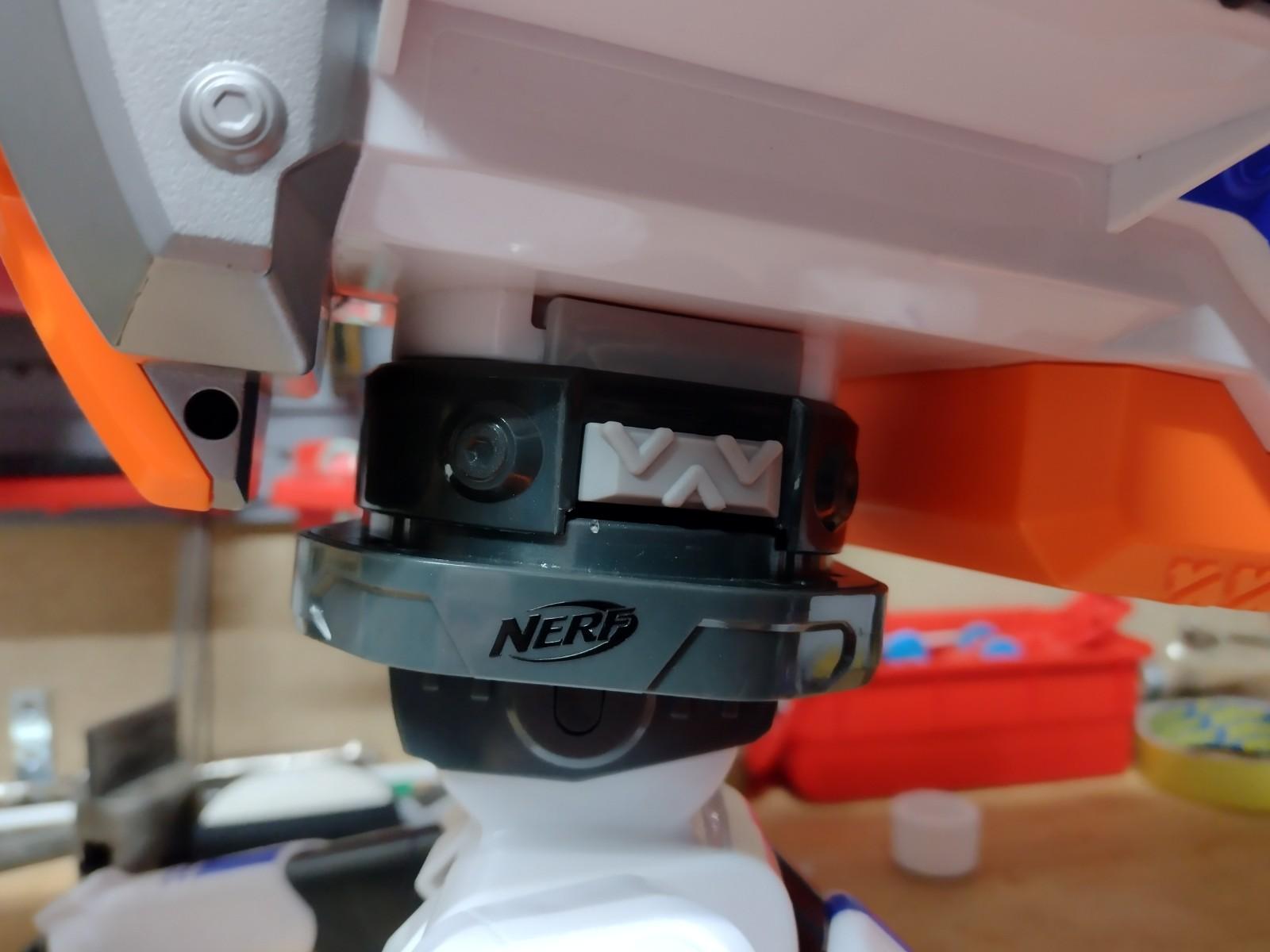

I found that adding a small dowel in the base of the tripod allowed the blaster to be mounted with a slight rise. This kept the darts relatively straight in flight. By all means play with what works for you.
Happy blasting