Tank Drive Robot With Wi-Fi Communication
by Showblown in Workshop > Metalworking
1315 Views, 13 Favorites, 0 Comments
Tank Drive Robot With Wi-Fi Communication
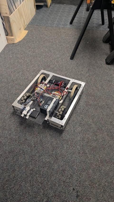
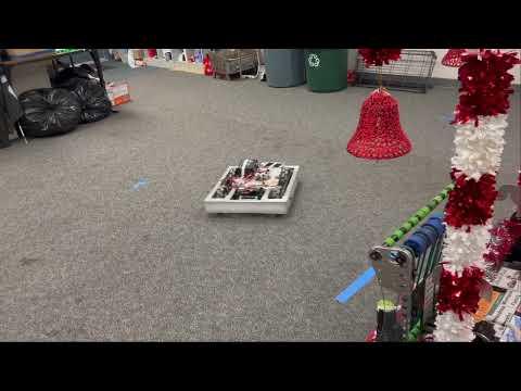
Welcome to our Instructable, where we go through our process of making a maneuverable Tank-Drive Robot. This project was made by 2 high school sophomores, Kyle and Shyamak. Kyle did most of the metalworking, while Shyamak did the programming. The CAD was done by both of us. Everything here is made 100% from scratch from the Wi-Fi interface to the metal parts. The code for the Driver Station can be found at my Github: Showblown/Personal-Driver-Station: A driver station that uses websocket communication to communicate with the ESP32 on the robot. (WIP), and the CAD file can be found on this Onshape link: https://cad.onshape.com/documents/1b3c648052fbf68128b0c9b2/w/846f041573950bf2c84e2219/e/c9c3394ca0927df0e9bb3a1f
Supplies
The materials you will need are:
10 ft of 0.125" x 2" x 1.5" metal extrusions
Sheet metal
Rivets
12v motorcycle battery
Arduino Mega (Any ATMega2560 board should work)
ESP32 (any model should work, however I used the ESP32-WROOM-32E)
Breadboard (preferably 2 if your ESP32 is large)
A 3.3v to 5v logic shifter (Only if your 2 boards work on different voltages)
WCP single stage gearbox (5:1 gear ratio, but you can adjust that)
2 12v CIM motors (You can use any motors that are compatible with the gearbox you are using) CIM Motor - VEX Robotics
2 motor controllers (We used Sparks by CTRE but you can use any that supports PWM)
Fusebox/PDH (We used this one: Amazon.com: WUPP 12 Volt Fuse Block, Waterproof Boat Fuse Panel with LED Warning Indicator Damp-Proof Cover, 6 Circuits with Negative Bus Fuse Box for Car Marine RV Truck DC 12-24V : Automotive)
Omni Wheels (our wheels were from Omni-Directional Wheels - VEX Robotics)
Background

During the beginning of our freshman year, both of us (Kyle and Shyamak) joined a robotics team called The Circuit Breakers, with the team number 3189. It was a team under the First Robotics Competition, a competition where thousands of high school teams all around the world compete to see who has the best robot for that season. Both of us were new to anything robotics related, and we were drawn to the challenge and excitement that the competition had. As the season progressed, we became friends and when our build season ended, we wanted to build our own robot to imitate the experience we had building our team robot.
Before we made our own robot, we took part in making the robot for the competition our team was a part of. Since neither of us had prior experience in robotics, it was a steep learning curve learning the fundamentals of robot design. Kyle became an electrician of the team, wiring motors and encoders to the robot and more, while Shyamak became a programmer, making motors move and implementing advanced mechanisms such as swerve drives (although this wasn't on the robot we created). For both of us, being on the team was an exhausting but fun experience, requiring brainstorming prototyping, and refining ideas at our lab. Through this process, we both found that our skills complemented each other, with Kyle's knowledge on wiring and electronics pairing with Shyamak's programming skills.
Although during our team competition we didn't win, the experience of creating a robot and being able to try again next year was invaluable. We learned so many knew things and with the build season coming to a close, we decided to create our own personal project--creating our own robot with little to no help from our team, being a simple bot that would let us make more complicated ones later. This project has been both challenging and rewarding, with us being able to practice our skills in robotics outside of the bubble created by FIRST and their partners, for example Shyamak being able to code a robot not using the WPI library, and Kyle having to things such as wires, batteries, and PDHs that weren't used in FIRST.
This robot was just the first of many projects that we will do in the future, where we intend to make robots using a swerve drive, an omnidirectional robot that can move in any direction without having to rotate, even though it's exponentially harder than a traditional tank drive that's used in this robot. Both of us, Kyle and Shyamak have had to overcome new things and work as a team, driven by our passion for robotics.
Introduction
To approach this project, we divided it into three main components: the client side/electronics, the wiring, and the robot side. On the robot side, we began with the robot frame, which serves as the foundation to support the motors and wheels, enabling the robot's movement.
Our initial step was to utilize Onshape, a 3D CAD program that allows for online part design accessible at any time. Onshape also provides the ability to generate G&M codes for CNC machining, facilitating precise fabrication of parts.
However, due to limited resources, we opted to manually fabricate the parts using traditional tools, including bandsaws, drills, belt sanders, hammers, and drill and tap sets. These basic tools allowed us to shape and assemble the components necessary for our robot.
For the client
Designing the Frame

We began by designing the frame, following several brainstorming sessions over a few days where we explored different iterations. Ultimately, we settled on a square frame with two sets of wheels, totaling four. The wheels are secured using ten brackets, all of which we hand-manufactured.
Designing the Parts
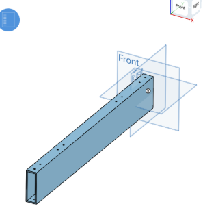

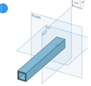
The first part we fabricated was the back of the frame, a 20-inch-long piece of 1” x 3” x 0.125” aluminum rectangular tube. We cut 16 holes in this piece to prepare for riveting the frame together. The type of rivets and the size of the holes can vary depending on the rivets you choose to use.
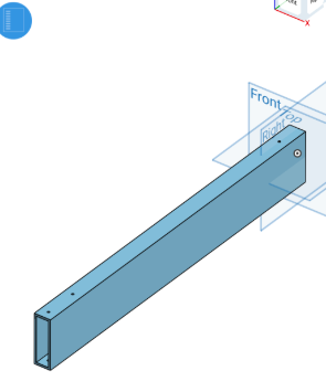
The next part we designed was a 21-inch piece of the same 1” x 3” x 0.125” aluminum rectangular tubing. This part needs to be manufactured four times, as it serves as each of the extrusions connecting to the back of the frame. We cut six holes in each piece to prepare for riveting the frame together. The type of rivets and the size of the holes can vary depending on the rivets you choose to use.
The next part we designed was a 21-inch piece of the same 1” x 3” x 0.125” aluminum rectangular tubing. This part needs to be manufactured four times, as it serves as each of the extrusions connecting to the back of the frame. We cut six holes in each piece to prepare for riveting the frame together. The type of rivets and the size of the holes can vary depending on the rivets you choose to use.
The last major part of the frame we made was a small block to connect each of the previously made parts together, forming sections that provide the structure for our wheels. This extrusion is a 4-inch piece of the same 1” x 3” x 0.125” aluminum rectangular tubing. As with the previous steps, we cut four holes to prepare for riveting the frame together. The type of rivets and the size of the holes can vary depending on the rivets you choose to use.
To help support the frame and prevent warping in the drivetrain, we added a simple piece of 1” x 1” x 0.125” aluminum square stock. This extrusion is 1 inch long and will also be riveted into the frame. Follow the same steps as before to create the necessary holes in preparation for the riveting process.
Creating the Brackets
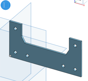
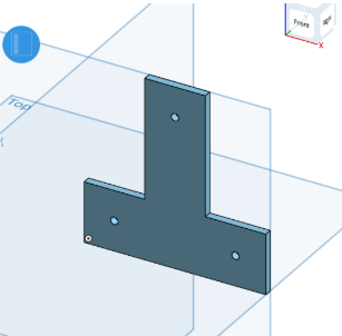
We now need to manufacture 8 of these brackets to hold the frame together after inserting the rivets. To make each plate, you will need a 6” x 24” piece of 0.125” thick aluminum. (We recommend getting extra material to account for any mistakes and the material lost due to the saw blade.) Each plate should be approximately 6” x 3”, with a section cut out in the center to provide space for the wheels that will rest inside the drivetrain. The ends of the plate should be 1 inch thick to ensure it lays flush on the frame. Afterward, mark the holes for drilling based on the holes you created in the base frame earlier. The more precise you are with your markings and measurements, the more square your frame will be, helping to avoid gaps.
This small, simple bracket is located at the bottom of the frame, holding the support bar in place to prevent it from falling out or warping. To manufacture this part, you'll need an additional 6” x 3” section of 0.125” aluminum. From this, you'll cut out a 3” x 3” square and shape it into a T, making each fork 1 inch wide. Drill the holes accordingly to fit your needs, following the steps described previously above.
Assembling the Frame

1. Assembling the Back of the Frame:
•Start with the 20-inch-long piece of 1” x 3” x 0.125” aluminum rectangular tube.
•Ensure that the 16 pre-drilled holes are aligned correctly for the riveting process.
•Place the 20-inch piece flat on your workspace as it forms the back of the frame.
2. Attaching the Side Extrusions:
•Take the four 21-inch pieces of 1” x 3” x 0.125” aluminum rectangular tubing.
•Align each piece perpendicularly to the 20-inch back piece, with the holes on each 21-inch piece matching the corresponding holes on the back.
•Rivet each 21-inch piece to the back frame, securing the frame's sides.
3. Connecting the Side and Back with Small Blocks:
•Use the four 4-inch pieces of 1” x 3” x 0.125” aluminum rectangular tubing as connecting blocks.
•Place each 4-inch block at the joints where the 21-inch pieces meet the 20-inch back frame, ensuring proper alignment.
•Rivet these blocks in place to secure the corners and reinforce the frame structure.
4. Adding the Support Bar:
•Take the 1-inch-long piece of 1” x 1” x 0.125” aluminum square stock.
•Position it in the middle of the frame to prevent warping in the drivetrain.
•Drill holes as needed and rivet this support bar into place.
5. Fabricating and Attaching the Brackets:
•Cut eight brackets from a 6” x 24” piece of 0.125” thick aluminum, each measuring 6” x 3”.
•Cut out a section in the center of each bracket to provide space for the wheels.
•The ends of the bracket should be 1 inch thick to ensure a flush fit on the frame.
•Drill holes in the brackets to align with the frame’s existing holes.
•Attach the brackets to the frame with rivets, ensuring a snug and secure fit.
6. Installing the Bottom Support Bracket:
•Cut a 3” x 3” square from a 6” x 3” section of 0.125” aluminum.
•Shape the square into a T, with each fork being 1 inch wide.
•Drill holes in the T-shaped bracket to align with the frame's bottom section.
•Rivet the T-bracket in place to secure the support bar and prevent it from falling out or warping.
By following these steps, you will have a strong and well-aligned frame ready for the next stages of your project.
Installing the Gearboxes

Installing the gearboxes:
1. Positioning the Gearboxes:
•Take two gearboxes that will be attached to the back of the four side extrusions.
•Align each gearbox at the back end of the side extrusions (21-inch pieces), with the gearboxes facing the center of the frame.
2. Drilling Holes for Mounting the Gearboxes:
•Mark the locations for the gearbox mounting holes on the back of the side extrusions.
•Ensure the holes are aligned with the mounting points on the gearboxes.
•Drill the necessary holes into the extrusions, ensuring they are large enough for the bolts or screws used to secure the gearboxes.
3. Mounting the Gearboxes:
•Use bolts or screws to attach the gearboxes to the side extrusions, ensuring a tight and secure fit.
•Double-check that the gearboxes are aligned correctly and facing the center of the frame.
4. Preparing for the Shaft and Bearings:
•Identify the shaft location that will pass through the side extrusions and the gearboxes.
•Drill holes through each of the four side extrusions at the points where the shaft will pass.
•The holes should be sized to accommodate the bearings that will support the shaft.
5. Installing Bearings:
•Insert bearings into the drilled holes on each side extrusion.
•Ensure the bearings fit snugly and are flush with the surface of the aluminum tubing.
•These bearings will allow the shaft to rotate smoothly while providing support and reducing friction.
6. Inserting the Shaft:
•Slide the shaft through the bearings on the side extrusions.
•Ensure the shaft is aligned correctly and rotates freely within the bearings.
7. Securing the Shaft:
•Attach any necessary components, such as collars or spacers, to keep the shaft in place and prevent it from sliding out of the bearings.
•Check that the shaft is properly centered and that the gearboxes are driving the shaft as intended.
By following these instructions, the gearboxes will be securely mounted to the side extrusions, and the shaft will be well-supported by the bearings, allowing for smooth operation of the drivetrain.
Adjustable Wheel Tension System


3. Adjustable Wheel Tension System:
Description: The system you're referring to allows the tension of the wheels to be adjusted by tightening or loosening screws at the front of the mechanism.
How It Works:
Screws at the Front: These screws are connected to a mechanism that either tightens or loosens the grip on the wheels.
Tightening the Wheels: When you screw in, it pulls the components together, increasing the tension on the wheels. This can improve grip and reduce wobble, especially useful for maintaining traction on different surfaces.
Loosening the Wheels: Unscrewing releases the tension, allowing the wheels to spin more freely. This adjustment can be beneficial in situations where less grip is required for smooth, uninterrupted movement.
Benefits: This system provides flexibility to fine-tune the robot’s performance based on the field conditions or specific tasks during a competition.
By understanding these concepts—gear ratios for power and speed management, omni wheels for enhanced movement, and the adjustable wheel tension system for maintaining optimal grip—you can optimize your robot for better performance in various scenarios.
In these 2 photos you can see the omni-wheels and our belt tension system. The belt tension system was made because we were having issues with our belts being loose so we made a threaded rod connected to an insert inside the frame that comes out the front to a plate that we tightened a nut onto.
What Are Gear Ratios?
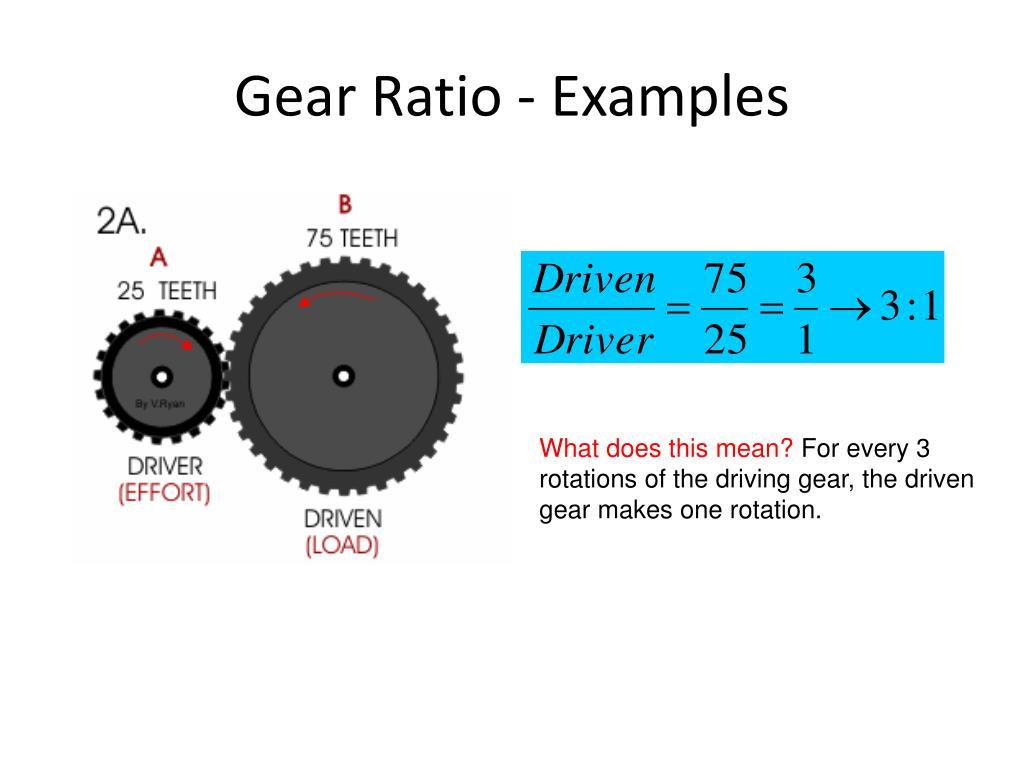
Definition: A gear ratio is the relationship between the number of teeth on two meshing gears or the rotational speeds of two interconnected gears. It determines how many times one gear rotates for each rotation of another.
Why It's Important: Gear ratios are crucial because they affect the torque and speed of the output shaft. A higher gear ratio increases torque but reduces speed, making it suitable for applications needing more power. Conversely, a lower gear ratio increases speed but reduces torque, ideal for faster movements.
Example in Robotics: In your drivetrain, choosing the correct gear ratio ensures the robot can move quickly while still having enough power to push or carry heavy loads.
Why We Use Omni Wheels
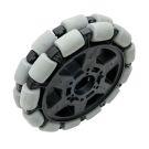
Definition: Omni wheels are specialized wheels with rollers mounted at an angle around their circumference, allowing them to move in multiple directions.
Advantages:
Enhanced Maneuverability: Omni wheels enable the robot to move not just forward and backward but also sideways and diagonally, making it highly maneuverable.
Smooth Turning: They reduce friction during turns, allowing for smoother and more efficient directional changes.
Getting Started on the Programming

The first thing that we have to do for the programming side is think about the way we handle it:
As you can see, we spent a lot of time brainstorming to program this in an effective manner the steps we ended doing were:
Wirelessly connect an xbox controller to the Laptop
Put the relevant controller inputs into a struct, and send it over to the wifi module (esp32) on the robot via websocket communication.
Send the struct over to the Arduino mega via serial communication
Set the motors to the desired value based on the controller input
However, at the time of writing, there weren't any software that were capable of doing this specific task, so I (Shyamak) had to make my own software capable of doing this.
Creating the Driver Station
The first thing that I thought about when making a driver station was about the software. I ended up choosing to use Visual Studio 2022, making a WFP project. This would allow me to export the software to become a .exe app later on and was a popular choice for making software, thus had a lot of plugins supported for it. One such plugin that I used was called Xinputium, which was the library I used for getting the Y axes of the joysticks, another being WebSocketSharp for the websocket communication to the arduinos. You can see more about XInputium here. The code that I used can be seen at the top via a github repository.
How the Driver Station Works
The driver station is broken into a few steps:
- Checking if the code is connected. As you can see from the code below, a few things happen:
The first function that gets called, CheckIsConnected(), runs in a while true loop as to constantly run the command over and over again. As you can see, the controller checks if the Controller is connected, and if it is, updates the gamepad and calls the Controller() function, otherwise if the controller isn't connected, it prints out a warning to the console and does nothing.
Next, the Controller() class constantly redefines a Struct with the axes of a few controller inputs, converts it to bytes using ByteConversion(inp), and then sends it over using SendData(data)
Lastly, SendData(byte[] data) sends over a websocket connection that sends the bytes over via a websocket connection using the WebSocketSharp library, which connects to the ip address of the ESP32 (this is because the ESP32 emits an AP wifi signal that we connect to, as I discuss later.) and sends the data over.
Next, let's talk about how we receive the information on the robot side.
Creating the Arduino Side
The Arduino side was in 2 parts: the ESP32 and the Arduino Mega. The ESP32 would receive the WebSocket signals using the ArduinoWebsockets library, decode it and send it over the to Arduino Mega. This method provides for there to be more outputs later on, as the Arduino Mega has more PWM output ports than the ESP32-WROOM-32E. This is the code for the ESP32:
The first few lines of code define the SSID and Password of the Access Point (AP for short) Wi-Fi signal that the ESP32 emits. Everything in setup() simply sets up the ESP32, setting up the Serial connections and starting the AP. In the loop() function, the ESP32 intercepts the WebSocket connection that the Driver Station sends, re encoding the bytes into data and printing them out, however still sending the struct in byte form to the Arduino Mega as that's faster.
Arduino Mega
This is the code for the Arduino Mega:
As you can see, this code also receives the bytes from the ESP32 and decodes it into values, which again get converted into a final struct. The joystick inputs (which are mapped from -1 to 1 for both joysticks) are then mapped to give the motor controller the correct PWM output (which we'll elaborate on in a bit). The PWM range for the motor controllers wasn't the traditional 0-127 being backwards and 128-255 being forward. Instead, the values 0-60 were neutral, with 180 being the lowest in one direction, with the power slowly increasing as the number goes to 120, where it's at full speed. Then at 200, the motor goes in the other way slowly, then speeds up until it reaches the maximum of 255 there. For this I had to map out multiple ranges for the joysticks, so the Arduino IDE's map() function proved useful for this.
Using a Logic Shifter
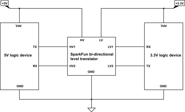
While the code for communicating between the 2 boards using serial is functional, there still remains one hurdle: the voltages don't match up. You see, the ESP32-WROOM-32E natively runs at 3.3V, while the Arduino Mega runs on 5V. Because of this, the two devices can't communicate to each other as their voltages don't match up. The solution to this is a logic shifter, a small device that, as the name suggests, shifts the voltage between the 2 devices so that they can communicate with each other. The pinout can be seen in the image above, and we connect the ports from the corresponding PCBs to each other on a breadboard. Keep in mind the RX and TX pins on the esp32 are 16 and 17 respectively.
How a Breadboard Works


A breadboard is a device that allows people to quickly wire up electronics by providing an array of holes, which people can stick DuPont wires into. This allows people to make more complex creations by being able to visualize what they're building, along with saving the hassle of plugging things directly into sockets. The slots on the outside (marked light blue on the picture) are generally used for power, while the ones on the inside can only travel horizontally. Another way to understand it would be to look at the copper wires on the other side of the breadboard in the picture on the right, and how currents can only travel through those copper panels.
How PWM Works
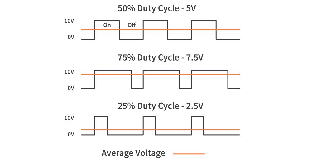
PWM is short for Pulse Width Modification, and is a method that is used for older motors. Rather than lowering the voltages of motors, sacrificing torque, we can instead use PWM which saves the torque of the motor. The way PWM works is by having the motor at 2 states: 100% power and 0% power, or ON and OFF. The way that it lowers the speed of the motor, however, is by tweaking the how long its on and how long its off. For example, if the motor is running at 100%, the motor stays ON constantly, and vice versa if its on 0% power. But if the motor is at 50% power, then the motor stays ON and OFF for the same amount of time, with the motor turning itself ON and OFF extremely quickly, as in multiple times per second. The amount the motor stays ON and OFF changes based on the percentage, so if it's at 70%, the motor is ON more than its OFF, and vice versa if the motor is at 30%. Arduino uses the AnalogWrite() function for PWM output, with 127 being neutral, 256 being 100% forwards, and 0 being 100% backwards.
Using Motor Controllers

To use the motor controllers, we had to wire them up according to the image above. The incoming voltage was the one that came from the PDH (linked at the top of the page in supplies needed), with the signal, ground, and voltage wires coming from the Arduino Mega. Keep in mind that the Arduino Mega only has a certain number of pins that support PWM output, with the specific pins being listed online.
Final Step
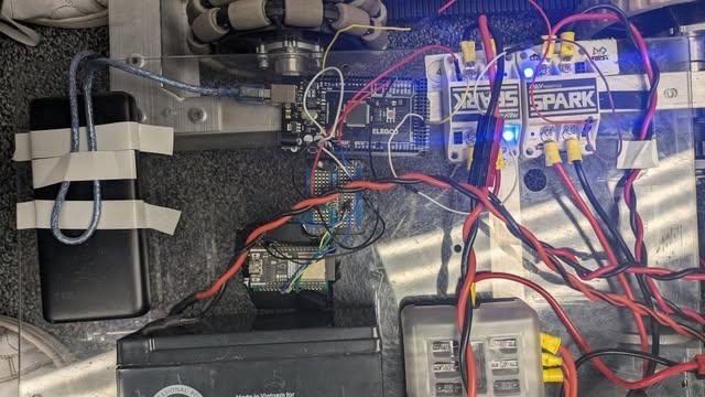
The last step is to wire everything together. We put a plexiglass panel on our robot where we housed all our electronics. Our 12v battery was wired to our PDH, which had two motor controllers wired to that. These were wired to the Arduino Mega via the pinout provided in earlier steps. You will also need a power bank to for the PCBs, and you can just connect it to any one of the PCBs via USB as the one thats powered powers the other. For reference see the image attached to this step. Congratulations! You've just made a state-of-the-art robot.