Target Robot Tutorial

This is a tutorial for a robot that used Arduino. It rolls around and avoids hitting walls. It also has a target on top of it that ping pong balls can be thrown at.
Supplies

- Arduino IDE
- Arduino board
- Breadboard
- 2 DC motors
- Driver board
- 4 Wheels
- 2 Ultrasonic distance sensors
- Battery and battery holder
- Switch
- Wires
- Cardboard
- Hot glue
- Duct Tape
- Soldering Iron
- Solder
- Arduino and breadboard holder(not required)
Declaring Pins and Variables
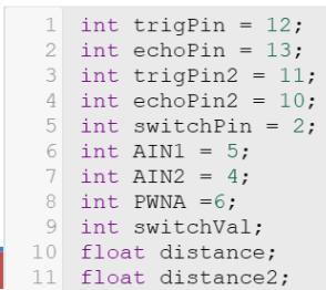
- Create a pin for the switch
- Create a variable to contain switch value
- Create first direction pin
- Create second direction pin
- Create PWNA pin for motor(must connect to a PWM pin)
- Create trig pin for ultrasonic sensor(call it “trigPin”)
- Create echo pin for ultrasonic sensor(call it “echoPin”)
- Create trig pin for second ultrasonic sensor(call it “trigPin2”)
- Create echopin for second ultrasonic sensor(call it “echoPin2”)
- Create a float variable named distance
- Create a float variable named distance2
Code Setup

- Declare every pin as output besides “a” and “b”. They are inputs
- The switch pin
- The echo pins for both ultrasonic sensors
- Begin serial monitor(not required but helps find errors)
Functions
Copy both of the functions that appear on the following 2 steps. These are for each of the ultrasonic sensor. The first function corresponds to the first ultrasonic sensor and the second function correspond to the second ultrasonic sensor. Make sure the variable and pin names match the ones that were specified in the “Declaring Pins and Variables” slide. Paste them after the loop function.
GetDistance Function
float getDistance()
{
float echoTime;
float calculatedDistance;
digitalWrite(trigPin, HIGH);
delayMicroseconds(10);
digitalWrite(trigPin, LOW);
echoTime = pulseIn(echoPin, HIGH);
calculatedDistance = echoTime / 148.0;
return calculatedDistance;
}
GetDistance2 Function
float getDistance2()
{
float echoTime2;
float calculatedDistance2;
digitalWrite(trigPin2, HIGH);
delayMicroseconds(10);
digitalWrite(trigPin2, LOW);
echoTime2 = pulseIn(echoPin2, HIGH);
calculatedDistance2 = echoTime2 / 148.0;
return calculatedDistance2;
}
Looping Code Pt1

- Have distance get its value from getDistance function
- Have distance2 get its value from getDistance2 function
- Have the switch variable get its value from reading the switchpin
Looping Code Pt2
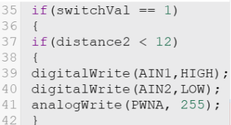
- Create an if statement that happens if the switch variable is 1
- Inside that if statement, create an inner if statement that happens if distance2 is less then 4
- In the inner if statement, make the motor spin counterclockwise at 150 speed
- End the inner if statement
Looping Code Pt3
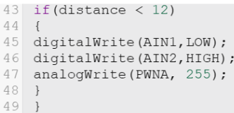
- Create a second inner if statement that happens if distance is less than 4
- In the second inner if statement, make the motor spin clockwise at 150 speed
- End the second inner if statement
- End the switch variable if statement
Looping Code Pt4
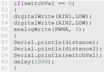
- Create an if statement that happens if the switch variable is 0
- Inside that if statement, turn both directions to LOW and the speed to 0
- End that if statement
- Serial print distance, distance2, and the switch variable on their own line(not required but helps find errors)
- Delay a second
Wiring Pt1, Arduino and Switch
- A finished wiring diagram is found at the end of the wiring section of the tutorial
- Wire 5V and ground from the Arduino to the breadboard
- Wire 1 side of the switch to ground and the other side of the switch to 5V. The switch will be on when it is on the 5V side and off when it is on the ground side
- The middle pin of the switch should be wired to whichever the switch pin is declared to in “Declaring Pins and Variables”
Wiring Pt2, Distance Sensors
- Wire the VCC pin of each distance sensor to 5V
- Wire the GND pin of each distance sensor to ground
- Wire trigPin, echoPin, trigPin2, and echoPin2 to whichever pin is declared to each in “Declaring Pins and Variables”
- Keep track of which trig pin and echo pin each distance sensor is connected to. The first distance sensor should only be wired to the first trig pin and first echo pin while the second distance sensor should only be wired to the second trig pin and second echo pin. Which distance sensor is which will matter during assembly
Wiring Pt3, Motors and Motor Driver
Connect the following pins on the motor driver to their assigned positions
- Connect Vm to VIN on Arduino
- Connect Vcc and STBY to 5V
- Connect GND to ground
- Connect PWNA to PWNA pin specified in “Declaring Pins and Variables”
- Connect AIN1 to first direction pin
- Connect AIN2 to second direction pin
- The red wire on the motors will be connected to A01
- The black wire on the motors will be connected to A02
Wiring Picture
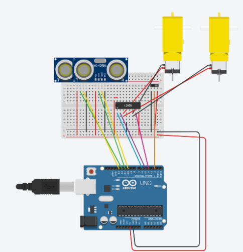
The motor driver in the picture is different then the motor driver used in this robot. Follow the wiring the was specified in the last slide for the motor driver. The distance sensors will not fit as shown in the image. They will not be on the breadboard during assembly.
Construction Pt1

- Connect wheels to each side of both of the motors
- Cut out 2 12 inch by 5 inch pieces of cardboard
- Cut 2 holes in both of the cardboard, one on each side. The top of the motor and the wires should be able to fit through it, not the whole motor.
- Stack the 2 pieces of cardboard and use hot glue to glue them together. This is the bottom plate
Construction Pt2
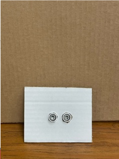
- Cut out 2 5 inch by 4 inch pieces of cardboard
- Cut 2 holes in the middle of both of the cardboard. The circular part of the ultrasonic sensors should fit in the holes. These are the small plates
Construction Pt3
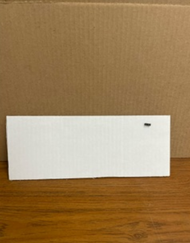
- Cut out a 3rd piece of cardboard the same size as the cardboard cut out in”Construction Pt1”
- Cut a small hole somewhere in the cardboard. The pins of the switch should be able to fit through it. This is the top plate
Construction Pt4

- Cut out 2 more pieces of cardboard that are a little more than 12 inches by 4 inches. These are the long plates
- Glue the small plates and long plates to the bottom plates. It should look like a box with the top off
Construction Pt5

Complete the wiring explained in the “Wiring” portion of the tutorial
Construction Pt6

- Glue the breadboard and Arduino in between the 2 holes in the bottom plate. Make sure they both touch the same long plate. Also make sure the Arduino’s connector the the battery holder faces toward the other plate
- Put the batteries in the battery holder
- Put the battery holder in between the 2 holes in the bottom plate. Make sure they touch the other plate that the Arduino and breadboard are not touching. Also make sure the connector of the battery holder can connect to the Arduino.
Construction Pt7
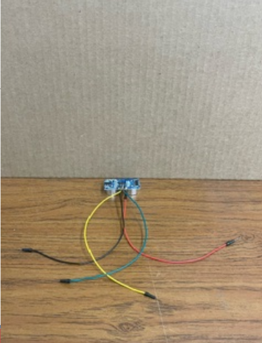
Solder a wire to each of the pins on both of the distance sensors. One of the distance sensors will need another 4 wires soldered onto each of the 4 wires already on it
Construction Pt8

- Place 1 distance sensor into each of the 2 holes in the small plate. Make sure the distance sensor that does not have extra wires soldered to it is closer to the breadboard
- Place 1 motor into each of the holes in the bottom plate. Make sure the wires can reach the breadboard
- Connect the distance sensors and the motors to the breadboard.
Construction Pt9

- Place the switch in the hole in the top plate with the pins facing towards the breadboard
- Solder a wire onto each of the pins on the switch
- Wire the switch to the breadboard.
- Use duct tape to attach the top plate to the rest of the robot
- Create a target and use hot glue to attach it to the top of the robot. The look of the target does not matter
Completed Code
Completed code for the project
Downloads
Constuction Video
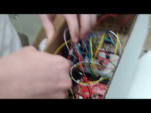
A video showing the construction of the project