Teaching the Laws of Signs Kit
by braulio777 in Circuits > Electronics
886 Views, 3 Favorites, 0 Comments
Teaching the Laws of Signs Kit

![KIMG0366[1].jpg](/proxy/?url=https://content.instructables.com/FE5/AFCG/I4C2PPLC/FE5AFCGI4C2PPLC.jpg&filename=KIMG0366[1].jpg)
![KIMG0374[1].jpg](/proxy/?url=https://content.instructables.com/FQT/4J3B/I4C2PPF1/FQT4J3BI4C2PPF1.jpg&filename=KIMG0374[1].jpg)
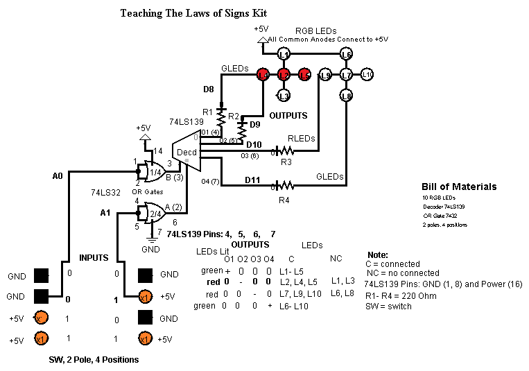
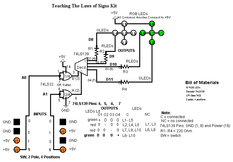
The device is based on a 2x4 decoder (74LS139) because this decoder shows a configuration that corresponds exactly in its inputs to the combination of signs of the operations of multiplication and division while its outpus give a result to each combination of inputs.
Bill of Materials


1 High Class ABS Plastic Speedy Box Enclosure 6.0"L x 3.5"W x 1.9"D
1 Arduino Uno Proto Shield (PCB only)
4 Resistor Carbon Film 220 Ohm 1/4 Watt 5% (In Bags of 10 and 100)
1 Pass-Through Female Headers for Arduino Shields - 1x8 and 1x6 Position (2 each)
10 LED MOUNTING HARDWARE,T1-3/4,CLEAR,STANDARD
1 CABLE,USB2.0,A/A,6 FEET,BLACK,USB-A MALE TO USB-A MALE
10 5mm Water Clear RGB LED - Common Anode
1 QUAD 2-INPUT POSITIVE OR GATE DIP-14 (74LS32)
1 Socket IC 14 Pin Dual Wipe Soldertail Low Profile 0.03 Inch Width
1 Decoder/Demultiplexer Dual 2-to-4 16-Pin Plastic Dip Tube (74LS139)
1 Socket IC 16 Pin Dual Wipe Soldertail Low Profile 0.30 Inch Width
1 Toggle Switch Single Pole Single Throw (On-Off) (MTS101) Solder 125 VAC @ 5 Amp 1/4 Inch Mounting
1 Switch Rotary Shaft Solder Lug 25mm 10M 4 Position
1 HEAT SHRINK TUBING,FIT221-1/16-Black, 4 FEET,Black POLYOLEFIN TUBING
1 KNOB,1/4 INCH SHAFT,POINTER,WITH SET SCREW
1 10 Color Stranded Wire Kit Assortmen
1 Breadboard Jumper Wire-One Pin Male to Male 15cm 10pcs
What you will need:
Soldering Station
Solder Roll
Plastic Cable Clamps 1/2"
Foam Tape
Wire Cutter
Pliers
Working With the Enclosure of Your Project 1


In this step, you will need to make a few holes: ones of 1/4" and another one of 3/8" in the front panel
Working With the Enclosure of Your Project 2


It´s important that this drill be made so that you can install the switch to turn (ON/OFF) your project. Note that this hole is 1/4" .
Completing the Holes in the Project


It´s imperative that this hole be made so that you have all of holes you need for the project. This hole is to pass through the enclosure the USB-A cable.
LED MOUNTING HARDWARE,T1-3/4,CLEAR,STANDARD


LED MOUNTING HARDWARE,T1-3/4,CLEAR,STANDARD is a support for installing the LEDs used in this prohect, and so showing a better presentation. In the current step, it´s necessary to install 10 sockets of this type where will be inserting the RGB LEDs.
Diagram 1

In the diagram 1, you can see the changes in the combination of inputs and outputs by observing the inputs (0 , 0) Minus, Minus for an output (+) Plus while the black and orange wires are respectively GND and +5V.
Diagram 2

In the diagram 2, you can see the different combination of inputs and outputs and also the use of black and orange wires for doing the connections.to GND and +5V respectively where you can observe the inputs (0, 1) Minus, Plus for an output (-) Minus.
Diagram 3

In the diagram 3, you can observe the changes in the combination of inputs and outputs but also can note that the black and orange colors are the wires used to do the connections in the rotary switch by representing the zeros and ones respectively. In this diagram is observable the inputs (1, 0) Plus, Minus for a result (-) Minus.
Diagram 4

In the diagram 4, you can see the changes in the combination of inputs and outputs by observing the inputs (1 , 1) Plus, Plus for an output (+) Plus.
Working With RGB LEDs 1


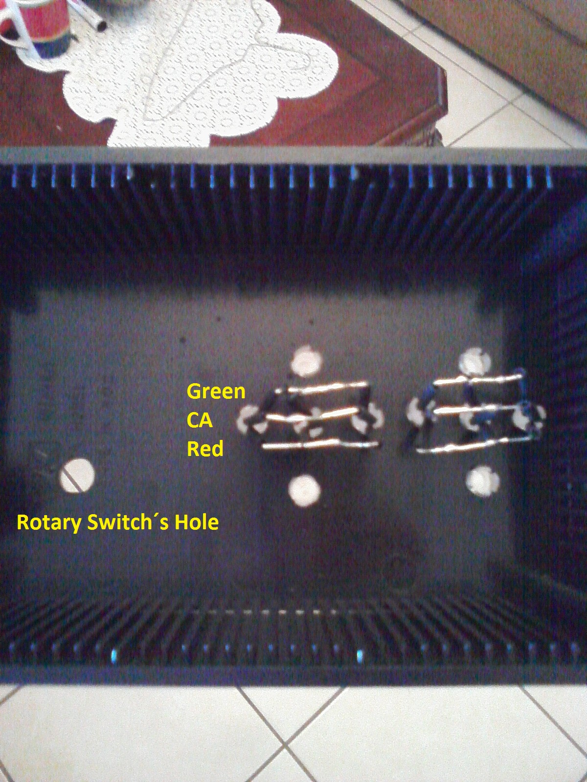
Before using the RGB LEDs, take 6 RGB LEDs and check them by using a multimeter for verifying their quality either good or bad. Also cut the blue terminal of each RGB.
Working With RGB LEDs 2


Once checked the 6 RGB LEDs, insert them into the sockets previously installed where you can use Heat Shring Tubing. Note that you should insert each LED with its red end toward bottom and for forming a line will be matching each color terminal of these RGB LEDs without blue terminal by interconnecting each group of 3 LEDs with their respective color terminal.
Working With RGB LEDs 3


Before connecting the 4 RGB LEDs, you can use Black Heat Shrink Tubing in each terminal of these LEDs if want.
Working With RGB LEDs 4


For this step, you can use orange wire for interconnecting the two groups of 5 LEDs and their common anode terminal. Also interconnect the rest of the common anodes of each LED except the green terminal of the bottom LEDs..
Working With RGB LEDs 5


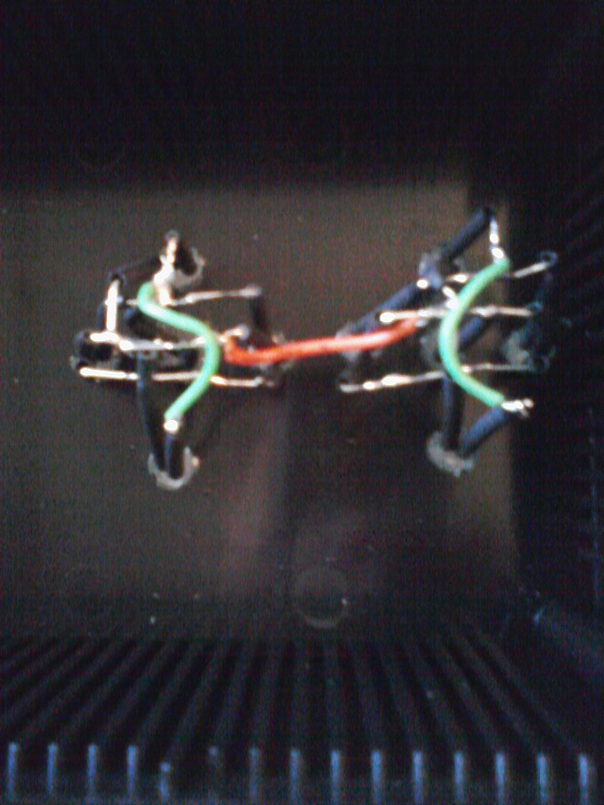
Now, interconnect the missing green terminals of the bottom LEDs and use green wire for these connections if want.
Installing the Toggle Switch ON/OFF


Install The Toggle Switch ON/OFF and connect an orange wire to one of its terminals while the other end of the orange wire to common anode of the RGB LEDs.
Preparing the Jumper Wires 1


Take 6 Jumper Wires Male to Male by thinking in the colors that you want to use in your project and cut them in two same parts and reserve for the following step.
Preparing the Jumper Wires 2


Cut wires for preparing your jumper wires male to male. In this steo, I´m preparing 2 green wires and 2 red wires for each group of RGB LEDs for being connected to their green and red terminal respectively. Also prepare 1 white wire and 1 brown wire for being connected to the 2 poles of your rotary switch, to A0 and A1 respectively.
Working With RGB LEDs 6


Of the jumper wires previously prepared in the step 17, connect the green and red wires of each group of RGB LEDs. From the left group, draw the wires for connecting to pin 10 the red one and to pin 11 the green one while from the right group, will connect to pin 8 the green one and to pin 9 the red one. For the rest of the wires, you should reserve until new instructions.
Working With the Rotary Switch 1


For working with the rotary switch 2 poles, 4 positions, you should check it so that you can know where is each position of each pole and so you do the connections correctly. In the connections done in the rotary switch, you can observe orange and black wires for the 4 positions. Also note that the 2 poles represent the 2 inputs of your project (A0 , A1 read from left to right) while the 4 positions represent the combination of inputs, that is, the black wires are 0´s and the orange wires are 1´s and these combinations of inputs in the left side comes up to down, but the right side comes down to up.
Working With the Rotary Switch 2


Connect the white and brown wires to the poles of your rotary switch by connecting to A0 and A1 respectively while the black and orange wires should be connected to GND and +5V respectively.
Preparing the USB-A Cable 1


Take the CABLE,USB2.0,A/A,6 FEET,BLACK,USB-A MALE TO USB-A MALE and cut one of its ends so that you can only leave the red and black wire that are +5V and GND respectively while removing the other two wires.
Working With the Rotary Switch 3


Using the USB-A cable prepared in the previous step and without forgeting pass it through the enclosure, do a node to support it inside of the box and connect it in your rotary switch to GND and +5V the black and red wire respectively. Besides that, draw an orange wire of your rotary switch for using later.
Working With the Rotary Switch 4


In your enclosure, install the rotary switch by adjusting perfectly the USB-A cable previously passed through the hole done in this and without forgeting connecting the extra orange wire that should be connected to the toggle switch ON/OFF.
Preparing the USB-A Cable 2
![KIMG0002[1].jpg](/proxy/?url=https://content.instructables.com/FWT/NLC4/I4C2Q5LI/FWTNLC4I4C2Q5LI.jpg&filename=KIMG0002[1].jpg)
In this step, you are going to install a holder cable so that you can support the knot done previously in your USB-A cable. Here I´m using a plastic adjusted holder of 1/2" with an adhesive base for fixing perfectly inside the box.
Working WithThe PCB 1


In this step, you are going to install the socket for the 74LS139 and 74LS32 then you need to install IC socket:: one of 14-pin and other of 16-pin. Also do the connections from these sockets to GND and +5V and connect the resistors by using black heat shrink tubing if want.
Working With the PCB 2


Do the rest of connections and install the Pass-Through Female Headers for Arduino Shields -(2) 1x8 and (1) 1x6 Position.
Working With the PCB 3


Now, you can insert the integrated circuits: 74LS139 aand 74LS32
Working With the PCB 4


Connect the red and green wires to pins 8, 9, 10, and 11 while orange and black wires to +5V and GND respectively by installing also white and brown wires to A0 and A1 in that orden.
Power Switch
![KIMG0375[1].jpg](/proxy/?url=https://content.instructables.com/FM7/FS6W/I4C2RFOE/FM7FS6WI4C2RFOE.jpg&filename=KIMG0375[1].jpg)
![KIMG0373[1].jpg](/proxy/?url=https://content.instructables.com/FGC/P5VM/I4C2RFMT/FGCP5VMI4C2RFMT.jpg&filename=KIMG0373[1].jpg)
You can also use a few foam tape close to the power switch so that you can write ON and OFF and so control the power of your project.
Completing the Project
![KIMG0344[1].jpg](/proxy/?url=https://content.instructables.com/FT1/2EUC/I4C2RFUF/FT12EUCI4C2RFUF.jpg&filename=KIMG0344[1].jpg)
To complete the project, you can use a few foam tape in the scale and so representing the combination of signs that you will want to select in this interesting project.
Using the Project 1
![KIMG0346[1].jpg](/proxy/?url=https://content.instructables.com/FV9/8ARA/I4C2RPQJ/FV98ARAI4C2RPQJ.jpg&filename=KIMG0346[1].jpg)
![KIMG0345[1].jpg](/proxy/?url=https://content.instructables.com/FQF/PUMW/I4C2RPIX/FQFPUMWI4C2RPIX.jpg&filename=KIMG0345[1].jpg)

![KIMG0376[1].jpg](/proxy/?url=https://content.instructables.com/F2K/ILVH/I4C2RFZ5/F2KILVHI4C2RFZ5.jpg&filename=KIMG0376[1].jpg)
The laws of the signs of multiplication and division in their first combination: minus, minus (- -) will result in a positive sign (+). Then select the first scale: minius, minus (- -) so that you can observe the result: plus (+)
Using the Project 2
![KIMG0351[1].jpg](/proxy/?url=https://content.instructables.com/FHI/RD2L/I4C2ROME/FHIRD2LI4C2ROME.jpg&filename=KIMG0351[1].jpg)
![KIMG0347[1].jpg](/proxy/?url=https://content.instructables.com/F8O/PG0K/I4C2ROEC/F8OPG0KI4C2ROEC.jpg&filename=KIMG0347[1].jpg)

![KIMG0377[1].jpg](/proxy/?url=https://content.instructables.com/FJS/5Z4O/I4C2RG32/FJS5Z4OI4C2RG32.jpg&filename=KIMG0377[1].jpg)
![KIMG0359[1].jpg](/proxy/?url=https://content.instructables.com/FON/ZE1K/I4C2RG64/FONZE1KI4C2RG64.jpg&filename=KIMG0359[1].jpg)
![KIMG0354[1].jpg](/proxy/?url=https://content.instructables.com/FBE/RYGQ/I4C2RG8G/FBERYGQI4C2RG8G.jpg&filename=KIMG0354[1].jpg)
![KIMG0369[1].jpg](/proxy/?url=https://content.instructables.com/F4K/227H/I4C2RG4B/F4K227HI4C2RG4B.jpg&filename=KIMG0369[1].jpg)
The laws of the signs of multiplication and division in their second combination: minus, plus (- +) will result in a negative sign (-). Then select the second scale: minius, plus (- +) so that you can observe the result: minus (-).
Using the Project 3
![KIMG0348[1].jpg](/proxy/?url=https://content.instructables.com/F8W/DZR7/I4C2RQN8/F8WDZR7I4C2RQN8.jpg&filename=KIMG0348[1].jpg)
![KIMG0350[1].jpg](/proxy/?url=https://content.instructables.com/FLA/MFET/I4C2RR05/FLAMFETI4C2RR05.jpg&filename=KIMG0350[1].jpg)


![KIMG0355[1].jpg](/proxy/?url=https://content.instructables.com/F0Q/1KW3/I4C2RR5W/F0Q1KW3I4C2RR5W.jpg&filename=KIMG0355[1].jpg)
The laws of the signs of multiplication and division in their third combination: plus, minus (+ -) will result in a negative sign (-). Then select the third scale: plus, minius (+ -) so that you can observe the result: minus (-).
Using the Project 4
![KIMG0349[1].jpg](/proxy/?url=https://content.instructables.com/FOJ/EW3G/I4C2RU6X/FOJEW3GI4C2RU6X.jpg&filename=KIMG0349[1].jpg)

![KIMG0372[1].jpg](/proxy/?url=https://content.instructables.com/F8B/85GD/I4C2RGHT/F8B85GDI4C2RGHT.jpg&filename=KIMG0372[1].jpg)
![KIMG0379[1].jpg](/proxy/?url=https://content.instructables.com/FQ5/7L36/I4C2RGHK/FQ57L36I4C2RGHK.jpg&filename=KIMG0379[1].jpg)
![KIMG0364[1].jpg](/proxy/?url=https://content.instructables.com/FIS/L3RM/I4C2RTWP/FISL3RMI4C2RTWP.jpg&filename=KIMG0364[1].jpg)
![KIMG0365[1].jpg](/proxy/?url=https://content.instructables.com/FX0/OOTE/I4C2RTR3/FX0OOTEI4C2RTR3.jpg&filename=KIMG0365[1].jpg)
![KIMG0372[1].jpg](/proxy/?url=https://content.instructables.com/FC5/B7KQ/I4C2RTLL/FC5B7KQI4C2RTLL.jpg&filename=KIMG0372[1].jpg)
The laws of the signs of multiplication and division in their forth combination: plus, plus (+ +) will result in a positive sign (+). Then select the forth scale: plus, plus (+ +) so that you can observe the result: plus (+).