Temperature and Humidity Node for HomeKit (MQTT)
7431 Views, 14 Favorites, 0 Comments
Temperature and Humidity Node for HomeKit (MQTT)

The goal of this Instructable is to create a sensor node that can capture temperature and humidity readings and publish it to an MQTT topic to be used in a "smart home" instance.
I wanted to create a cost-effective solution for creating my own temperature and humidity sensor that can be integrated into Apple HomeKit. The problem is that certified HomeKit devices and sensors can be expensive or difficult to obtain depending on your region. With some research, I stumbled upon an amazing project called Homebridge. As cited from their Github, "Homebridge is a lightweight NodeJS server you can run on your home network that emulates the iOS HomeKit API". There is an abundance of information of setting up Homebridge on their website, and I chose to run my Homebridge instance on a Raspberry pi model 3B.
I also wanted to create the sensor so that it can be used in other "smart home" solutions such as Home Assistant and thus made the decision to make use of the MQTT communication protocol for the project.
Supplies
The following supplies are required to create the sensor node:
- ESP-01 Module (or other ESP8266 variant)
- Any 5V 1A Power supply
- ESP8266 Programmer or USB to TTL Serial converter
- 3.3V voltage regulator
- AM2301 (DHT22) board module
- Male / Female power adapters
- Any enclosure for your components
- Hot glue
- Solder / Solder iron
- An operating MQTT server*
- An operating Homebridge instance
Optional supplies
- 3D Printer or 3D printing service (for enclosure)
- Raspberry PI
Downloading Required Software


The first step of the project is to configure the WiFi module (ESP8266) to communicate with your MQTT server
Before you can start to program the ESP8266, you will have to download some software first.
- Download and install the latest Tasmotizer .exe for Windows from this link. Tasmotizer is a tool that can be used to flash the ESP8266 board with custom firmware. More information about Tasmotizer can be found here.
- We will be flashing the ESP8266 with firmware known as Tasmota. Tasmota is opensource firmware for ESP8266 devices with a wide range of functions, including MQTT. Download the latest tasmota.bin file from this link. However, I prefer to use build 8.5.0.
In the next step we will prepare the required hardware to flash the ESP8266 with Tasmota.
Prepare Hardware to Flash ESP8266


In order to flash the ESP8266 with Tasmota using the Tasmotizer tool, the ESP8266 needs to be configured to allow firmware flashing. Luckily this is as easy as connecting pin GPIO_0 with Ground. An easy way to achieve this is to solder male and female header pins to the ESP8266 programmer. as shown in an attached photos.
Steps:
- Place the ESP8266 into the programmer
- Connect the two wires that will now connect GPIO_0 and Ground together.
- Before connecting the programmer to your Computer, proceed to the next step.
Flashing Your ESP8266 With Tasmota


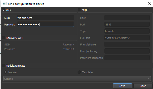
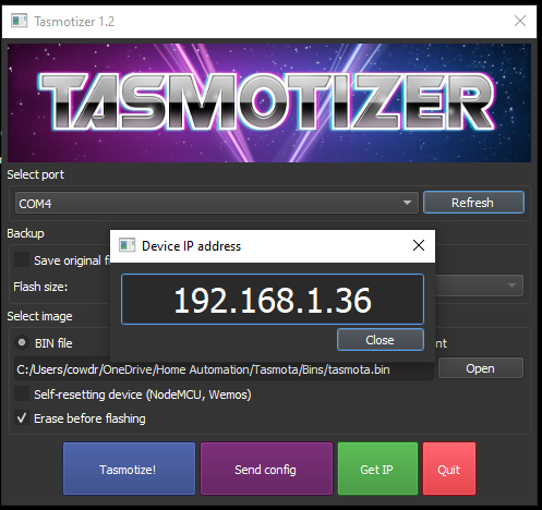
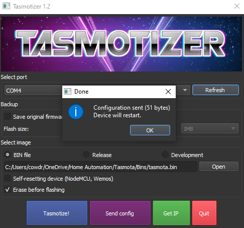
In this step we will be flashing your ESP8266 with Tasmota.
- Open Tasmotizer on your computer.
- With your ESP8266 in the programmer and GPIO_0 and Ground connected, plug the programmer into your computer.
- Click the refresh button in Tasmotizer to refresh the port, it should update. Please note that your port number will most likely be different.
- In the select image section of Tasmotizer click on open, and select the tasmota.bin file you downloaded in a previous step.
- Click on Tasmotize! and wait for the process to complete, You will be promted with a message when the process finished. Click on OK.
- Unplug the programmer from your computer
- Disconnect your GPIO_0 to Ground connection on the programmer and plug the programmer back into your computer.
- Navigate back to the Tasmotizer program
- Make sure the correct port is selected
- Click the "Send config button"
- Enter your WiFi SSID and Password (please note this must be a 2.4 GHz WiFi network due to an ESP8266 hardware limitation) and click save
- Wait around for 20 seconds
- Click the "Get IP" button.
- If everything worked, you should be presented with a valid IP address for your newly flashed ESP8266 module. Also if the module does not provide you with an IP address, log into your router and scan for any new devices, or use an application like FING to find network devices.
*Troubleshoot: make sure the correct port was selected in Tasmotizer, and that your ESP8266 is in flash mode (GPIO_0 and Ground connected for step 1-6. For step 8-14, GPIO_0 and ground should not be connected).
In the next step, we will be configuring the wifi module for MQTT and to accept the Temperature and humidity sensor
Tasmota Configuration on ESP8266


In my example, the ESP8266 joined my WiFi network with an IP Address of 192.168.1.36. I will now enter this in my browser.
- Enter the IP Address that Tasmotizer provided you into your browser and you will be connecting to your instance of Tasmota running on your ESP8266.
- Click on Configuration --> Configure Other and change your device name and friendly name to something appropriate, I will use "Demo1"
- Next we are going to configure the MQTT server by clicking Configuration --> Configure MQTT (At this stage I am assuming you have a running MQTT broker.) You have to fill in your MQTT information here.
- Enter your MQTT host address
- Enter your MQTT port
- For client I will be using "Demo1"
- In my case, I have a local MQTT server that is not exposed over the internet no Username or Password, you should enter the appropriate Username and password.
- I will also update the Topic to "Demo1"
- Click on save and wait for the module to restart.
- Now I want to update the interval that the module will post readings via MQTT to 5 seconds for this demo
- Navigate to Configuration --> Configure Logging and update telemetry setting to something appropriate to your needs. A practical value for a real world conditions will be around 10 minutes.
- Finally we want to configure the module to accept values from the A2301 (DHT22) sensor module.
- Navigate to Configuration --> Configure module and set the type for GPIO_2 to be AM2301 (2). Click save and wait a few seconds before navigating to the main menu.
- At this stage you will see the module presents you with Temperature and humidity readings of "null". In one of the next steps we will connect the Sensor to the ESP8266 to fix this.
In the next step we will be connecting the ESP8266 to a power supply and AM2301 sensor to provide us with real sensor readings.
MQTT Setup Confirmation


Before finalizing the project and creating a nice enclosure, I'd suggest performing a quick test run using a breadboard and power supply.
- Connect the ESP8266 and AM2301 board module to a 3.3V power supply. The ESP8266 board will be damaged if you use a greater voltage.
- Connect the data pin of the AM2301 board module to the GPIO_2 pin of the ESP8266
- Turn on the power supply and hopefully no magic smoke escapes from the devices.
- After a few seconds, navigate to the IP address of your ESP8266 on a browser on the same network. At this stage the AM2301 readings should be visible and display actual values and not NULL.
- To verify that your MQTT configuration works, download a free windows app from the windows store known as MQTT Explorer
- Connect the application to your MQTT server by entering your MQTT broker details and clicking "Connect"
- Your ESP8266 will be broadcasting an MQTT message at the time interval you configured earlier to the "tele/Demo1/SENSOR" topic.
The temperature and humidity message payload is a JSON object with format:
{"Time": "2020-12-26T12:54:33","AM2301": {"Temperature": 27.1,"Humidity": 57.3,"DewPoint": 17.9},"TempUnit": "C"}
This JSON message will later be parsed to be consumed the Homebridge software to expose the sensor to Apple HomeKit
Final Circuit

The final circuit to be embedded in the enclosure (next step) is very simple.
The ESP8266 and AM2301 (DHT22) needs 3.3V to operate. For this reason a DC step-down converter (3.3V) was used. Please refer to the attached diagram for reference.
Depending on your needs the power delivery can be altered, as long as the ESP8266 only gets 3.3V. For this reason the step-down converter is not in the schematic.
Enclosure

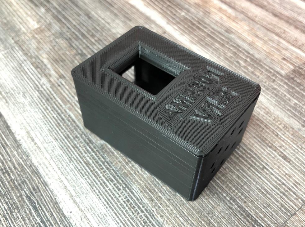


The final enclosure I went with was designed in Fusion 360 and exported to be 3D printed. The files to print can be downloaded from this link.
If you do not have access to a 3D printer, any electronics or similar enclosure should do the trick.
Homebridge Setup



*This Instructable assumes that you have a running instance of Homebridge on your local network.
- To integrate the MQTT temperature and humidity sensor into your Homebridge instance, navigate to the Homebridge plugin store and search "MQTT".
- Install the homebridge-mqttthing plugin an restart your Homebridge instance.
- Navigate to your Homebridge configuration file and add two new accessory entries as shown below:
"accessories": [{"accessory": "mqttthing","type": "temperatureSensor","name": "Demo1 Temperature","url": "http://192.168.1.98:1883","username": "","password": "","topics": {"getCurrentTemperature": {"topic": "tele/Demo1/SENSOR","apply": "return JSON.parse(message).AM2301.Temperature;"}}},{"accessory": "mqttthing","type": "humiditySensor","name": "Demo1 Humidity","url": "http://192.168.1.98:1883","username": "","password": "","topics": {"getCurrentRelativeHumidity": {"topic": "tele/Demo1/SENSOR","apply": "return JSON.parse(message).AM2301.Humidity;"}}}],
As you can see the MQTT payload of the temperature and humidity needs to be formatted for Homebridge to understand it. You can now save your Homebridge configuration and restart it.
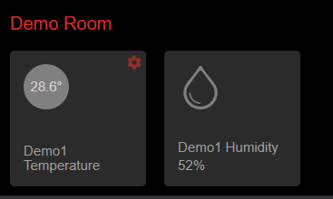
When you now navigate to your Homebridge accesories, you should see two new entries (Demo1 Temperature and Demo1 Humidity).
You can now also navigate to your Home app on your apple device and the temperature and humidity sensor will appear there as well.