Test and Repair a Clothes Dryer Switch
by Dustin Rogers in Workshop > Repair
8693 Views, 18 Favorites, 0 Comments
Test and Repair a Clothes Dryer Switch


A family member gave me a fairly new electric clothes dryer that they recently replaced. It worked...but it would only get warm on one setting. I had originally planned to part it out and use the motor for some random project, but after seeing how good of shape it was in, I decided to see if I could fix it.
After a little research online, the consensus was that the temperature switch was probably bad. Unfortunately, this dryer has the temperature switch built into the main timer switch. Luckily, a wiring diagram for the dryer was attached inside the back panel. I have enough experience with reading wiring diagrams that I was sure I could figure this out. Follow along to see how to test this style of switch, as well as testing any other switch that you may have a diagram for.
There are a few things I needed to test this switch:
- Volt/Ohm meter
- phillips screwdriver
- small flathead screwdriver
- wiring diagram (most are found inside the back panel of an appliance).
Continue reading or just watch the video:
Remember - even if you don't vote for me, vote for somebody in the contests.
Basic Use of Tools

Screwdrivers are self explanatory, but some may be unfamiliar with wiring diagrams, switch schematics, or a volt meter. This will be a very basic run down.
Volt meter (Ohm meter)
The cheapest of cheap volt meter can be used for this test. Analog or digital, it doesn't matter. For this particular test we are going to be testing with the Ohm settings. The Ohm symbol looks like an upside down horseshoe. Ohms is the measure of electrical resistance, the higher the number, the greater the resistance. Infinite resistance means that there is no connection. As far as this test goes, we'll either see very low resistance of 0 to 2 ohms (depending on the meter) or infinite resistance (out of limits).
Wiring diagrams/switch schematics
Wiring diagrams can be fairly confusing, so for simplicity I'll be focusing on the switch schematic that is included on the wiring. You'll notice in this schematic that the switch positions are indicated on the left side (Auto-Reg/High, Auto-Low Heat, Timed-Reg/High, Timed-Low Heat). Along the top, you'll see two letters in each column. These letters indicate the terminals to test. On the right, you'll notice what each grid pattern means (switch open, switch closed, etc).
Testing the Switch


You've got your meter set to read Ohms, switch schematic in hand, the appliance unplugged, the back panel is removed, time to take some notes. Some switches have single wires hooked to each terminal. The wires are color coded, so you'll want to pay attention to which terminal each wire comes off of. I find it easiest to take a picture or two with a digital camera so you can reference it when putting the wires back on. If no camera is available, just draw a diagram of the backside of the switch and mark where each color wire hooked on. This switch only had three connectors - one 4-wire connector, one 3-wire connector, and one 2-wire connector. Each connector will only go in one place so there's no confusion. These connectors, whether single wire or multi-wire are generally pretty tight. When disconnecting them, DO NOT pull them by the wire. Grab only the connector. I typically use a small flat screwdriver and gently pry underneath the connectors.
Once the wires are disconnected, you'll notice that each terminal is labeled. From top left to bottom left the terminal order is A, B, C, H, X, T, F. You'll notice that each of those letters correspond to a column in the switch schematic. To test the switch, you first turn the switch to the position you want to test. With the switch on the auto-high setting, connect one of the meter leads to terminal T and the other meter lead to terminal F. Our schematic shows that this connection should be open, so there should be infinite resistance. Next, move the meter leads to terminals T and X. This should have zero or very low resistance (< 1 ohm).
Continue checking each pair of terminals for each switch setting. If you have resistance between two terminals that should be open, then there is a short in the switch. If you have infinite resistance between two terminals that should be closed, then you have a lack of continuity - meaning electricity cannot flow. If the switch checks out and your appliance was not working correctly, then there is likely a different component that is faulty.
The problem that I had with this switch was that the terminals C and A never had continuity no matter what switch position was selected. Most people would just replace the switch, but this particular switch is ~$85 new. I decided it would be worth it to open the switch to see if it could be fixed. Read on if you want to see what I found.
Repairing the Switch


Some of these switches come apart - others are sealed together. Luckily, this one comes apart. I started by removing the timer motor from the terminal side of the switch by removing the two Phillips screws. Holding the switch firmly together, I flipped the switch over so the knob side was facing up. I removed the metal plate, which revealed seven copper strips that were attached to each terminal. The opposite end of each strip had a small round electrical contact on one or both sides of the strip. This switch works by using the plastic arms to push the needed strips together when the switch is in a certain position. This is what the switch schematic refers to as 'open' and 'closed'.
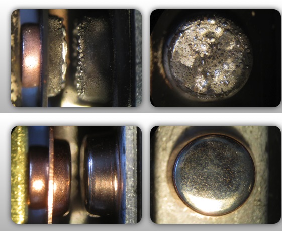
The issue with this switch was that the connection between terminal C and A were never closed. With the switch open, I could now see that the contact ends of the strips for A, B, and C were black (no picture - sorry). When the switch is in the proper position, the contacts for C, B, and A would all be pushed together, but I noticed that the contacts between B and A were very rough and showed signs of arcing. The third pic in this series was borrowed from Google images and it shows a comparison to how good contacts look (bottom) compared to contacts that have been arcing (top). I turned the switch so the contacts would be open and then used a small flat file to clean up the face and edges of the contacts. I tested between terminals A and C and had continuity!! I turned the switch a few times testing between A and C each time it closed and got intermittent results. Sometimes I'd have continuity, other times I wouldn't. I finally figured out that if I put the slightest bit of sideways pressure on strip A, that the continuity would return. With these copper strips having a bit of spring characteristic, I decided to just tweak strip A so that it was slightly closer to strip B, therefore it would make better contact with it. The only real concern with doing this was to make sure that the contacts are NOT placed close enough together for electricity to arc between the two when the contacts should be open. There is a plastic divider between strip A and B that limits how far strip A will travel. I used a small flat screwdriver to pry/bend strip A ever so slightly so that it is angled a bit closer to strip B. There's still plenty of air space between the two contacts to prevent short circuits. Once again, testing for continuity, everything checks out as it should.
I reassembled the switch and re-installed it in the machine. Now the machine has heat on all settings and I just saved $85.
Planned Obsolescence??

For many years, manufacturers have been designing products to fail prematurely. "The rationale behind the strategy is to generate long-term sales volume by reducing the time between repeat purchases (referred to as "shortening the replacement cycle")" (wikipedia). Many times parts are designed to fail shortly after the warranty period expires.
This particular dryer was manufactured in November 2011 and wasn't purchased until sometime in 2012. So in 3 years or less, the switch on this failed. The original problem was a combination of arced contacts and insufficient contact pressure to maintain continuity, which is likely what caused the arcing in the first place. After bending the copper strip, there is plenty of contact pressure there to maintain good contact - which should prevent arcing. Was this switch designed to fail in this manner? Even before any modifications, the copper strip was resting against the plastic divider that is molded into the switch case. Had it been designed so the divider was 0.5 mm thinner or 1 mm closer to the other terminal would this failure have ever occurred? It makes me wonder...
Regardless, this fix saved me some money and kept the thing out of the landfill (for now) and if the above holds true, then it was likely a lifetime fix as far as this switch is concerned. Hopefully the next thing that breaks will be similarly serviceable. I found this photo on a site that I've ordered "repair" parts from before. And couldn't agree more.
Thanks for reading to the end. I hope this gives you something you can add to your tool belt that can help you save some money in the future. I'd appreciate your vote. If you have any questions or comments, leave them below.