Testing the MP6550 Motor Driver With Arduino
61 Views, 1 Favorites, 0 Comments
Testing the MP6550 Motor Driver With Arduino
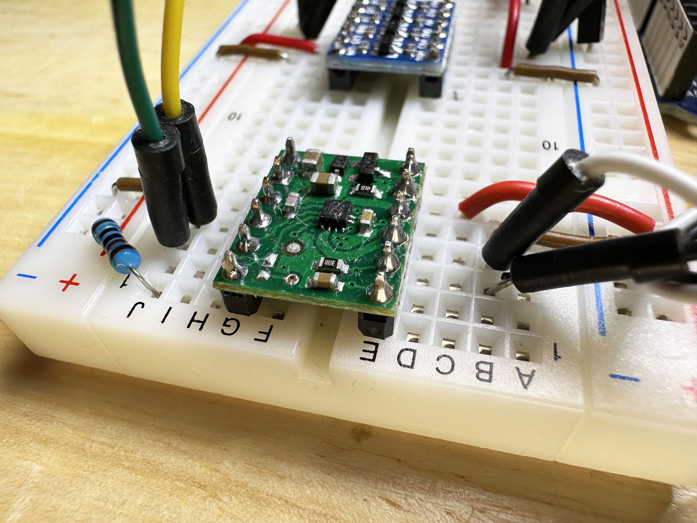
This is an Instructable demonstrating a circuit and an Arduino code to control the speed and direction of a DC motor. I am using it to test out the basic functions of the Pololu MP6550 DC motor driver carrier. In the near future I will use a couple of these motor drivers to control 12-volt DC motors with a 12-volt battery. I have not used this motor driver before so I have tried to keep the circuit and Arduino code as simple as possible.
Supplies
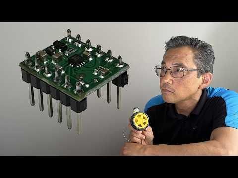
Pololu MP6550 DC Motor Driver Carrier
UNO microcontroller (e.g., Arduino UNO, but min is from Elegoo)
5-volt DC motor (and a way to connect it to the breadboard)
9V battery and battery connector for the UNO
Solderless Breadboard
Breadboard power supply capable of both 3.3 Volts and 5 Volts
Logic Level Converter
10 kilohm resistor
10 kilohm potentiometer
Momentary push button (for the breadboard)
Jumper wires (for the Breadboard and UNO)
Soldering iron and solder (if the motor driver needs the pins soldered on)
Why Use a Motor Driver?
The digital pins of microcontrollers, like an Arduino UNO or in this case an UNO clone, are not capable of powering a DC motor directly. However, if you want to control the speed and the direction, you need a something to provide the “brains” of the setup. In this case, the Pololu MP6550 DC Motor Driver Carrier will deliver the power to the motor, and the UNO is the brains. The motor driver and microcontroller make up a motor controller circuit.
The Pololu MP6550 Motor Driver Carrier
There is a lot of information on the Pololu website and I will include a link at the end of this Instructable.
I chose this motor driver because it uses MOSFETs and that it would therefore be more efficient than the L329 motor drivers I have used in the past. It also is able to deliver more than one Amp continuously, so it should be able to handle the project that I have in mind.
There are other functions of the motor driver, but these are outside the scope of this Instructable, which is to get the motor running and be able to switch speed and direction.
The Logic Level Converter
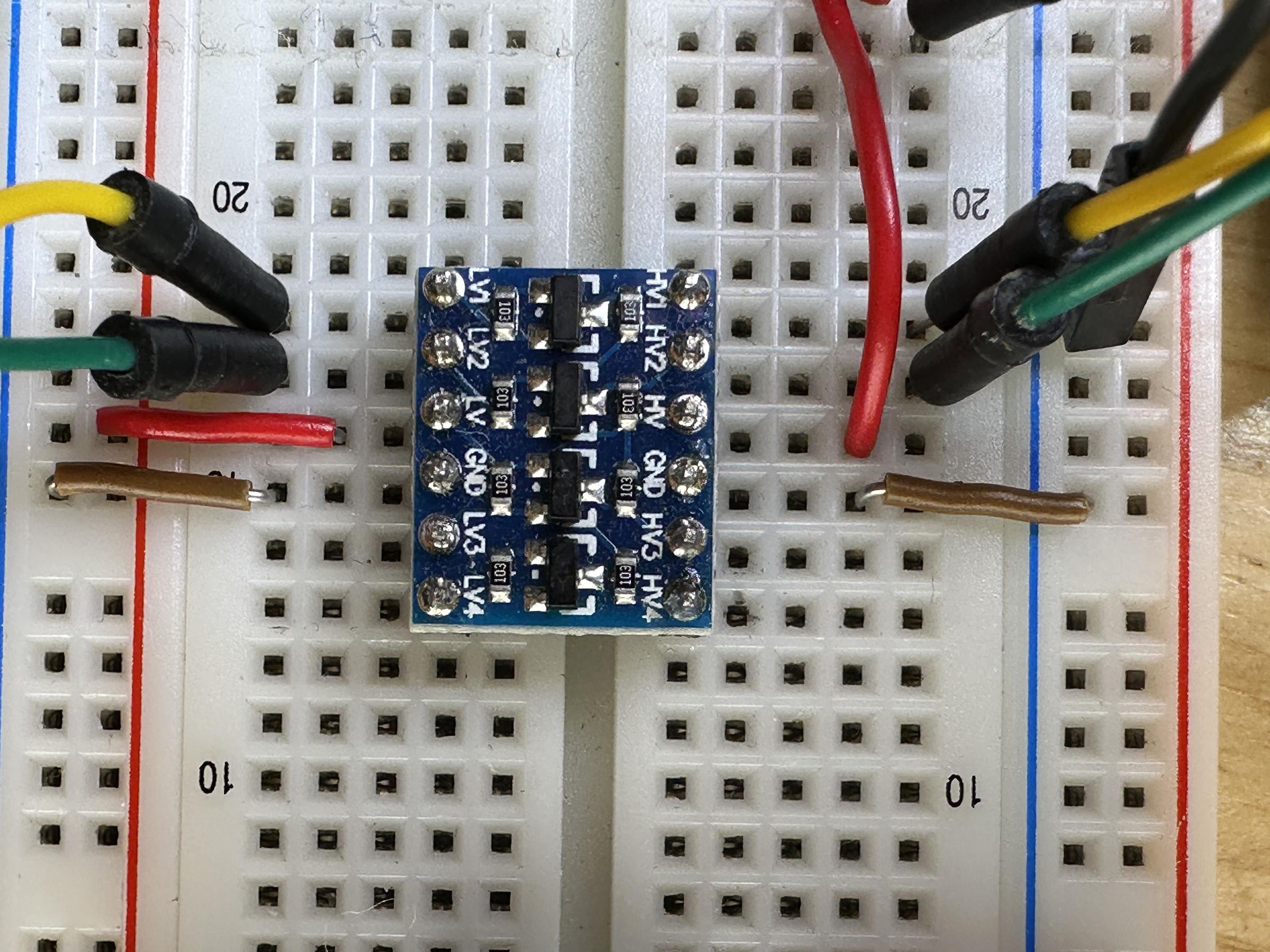
The voltages of the motor driver and the UNO microcontroller are not compatible. The motor driver is a 3.3-volt device, but the UNO runs on 5 volts. So, I am using a Logic Level Converter to go between the UNO and the motor driver. This little circuit board must be powered on both the higher-voltage and lower-voltage sides, and then the digital inputs/outputs can be connected through the converter as shown in the diagram below.
There are other microcontrollers, such as the Arduino Due or ESP32, that run on 3.3 volts, so if you used one of those, you would not need the converter.
The Circuit
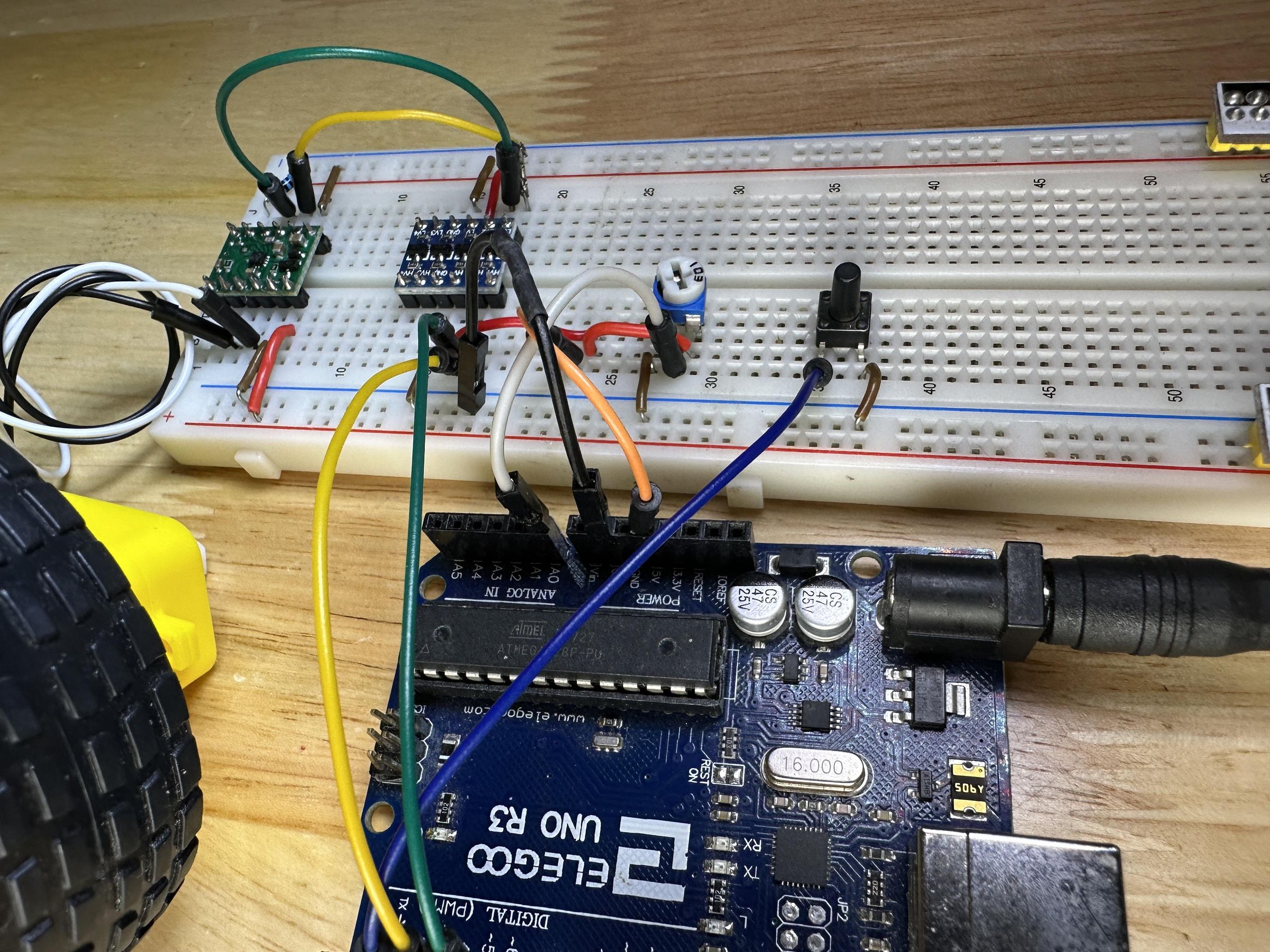
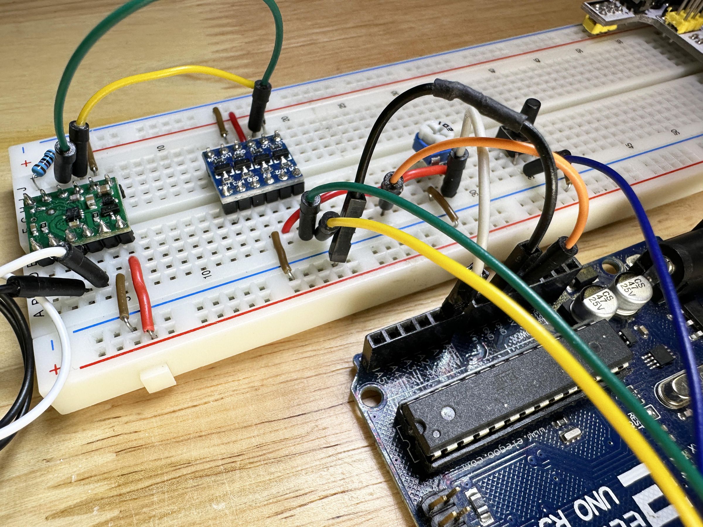
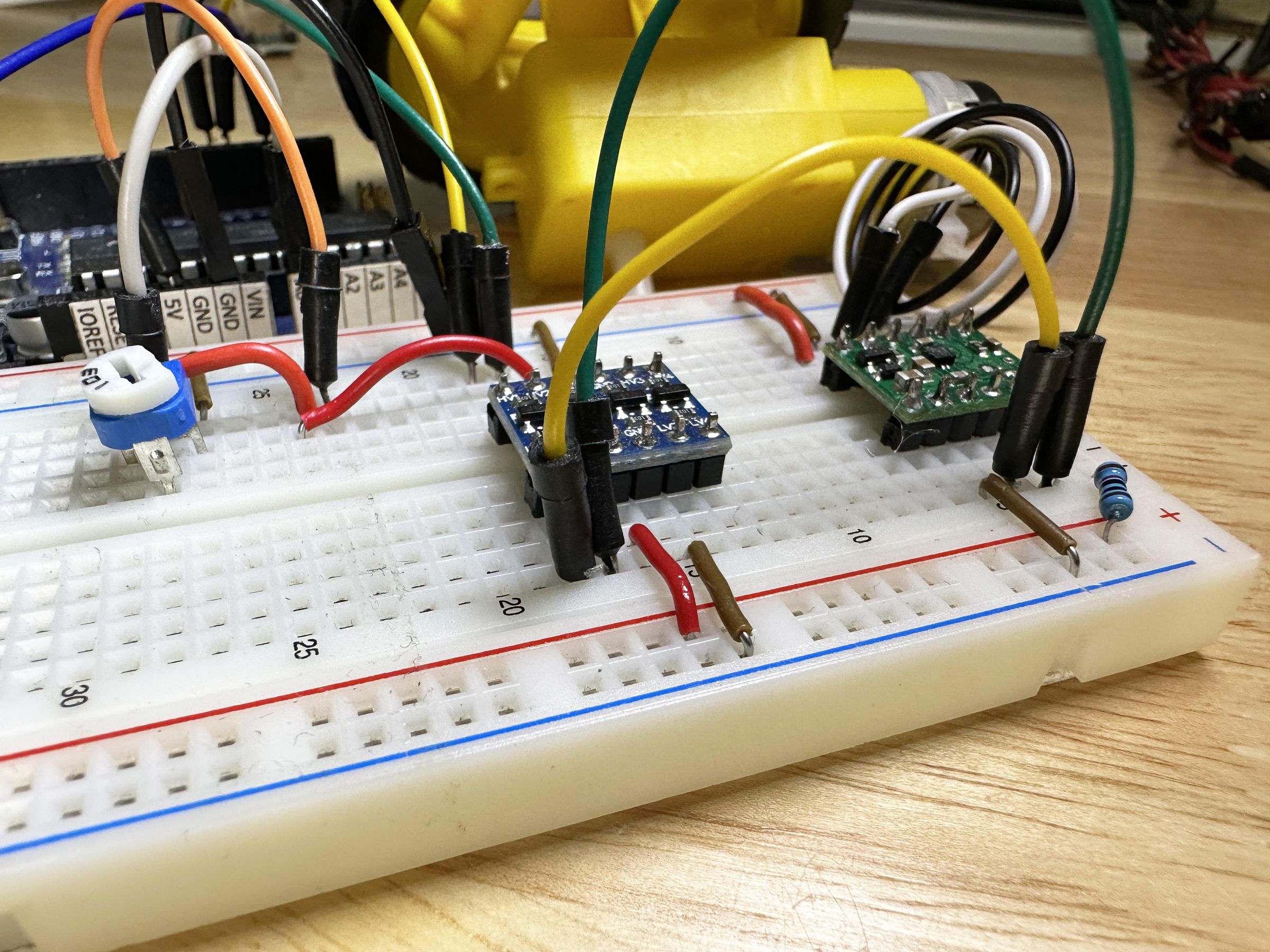
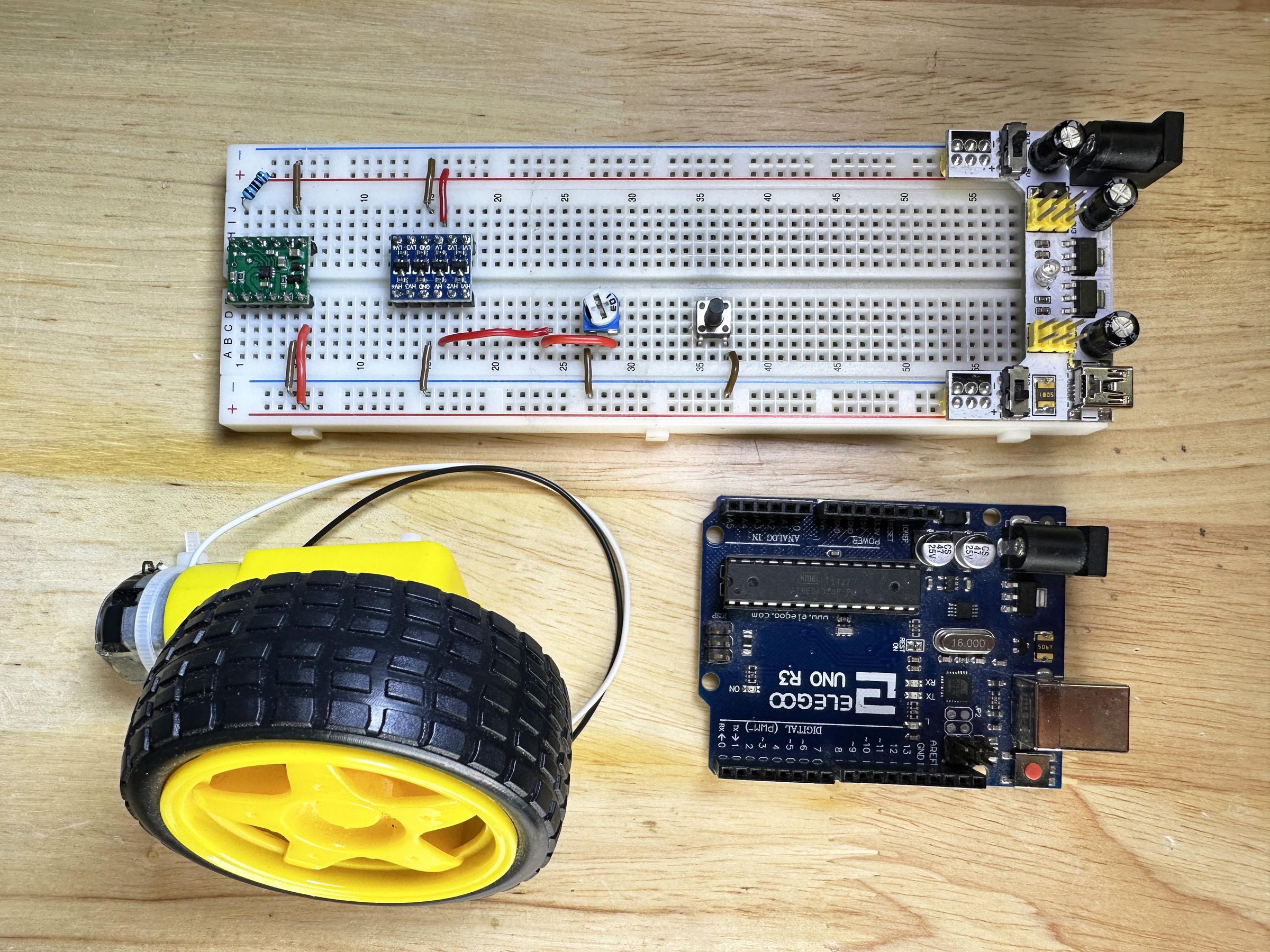
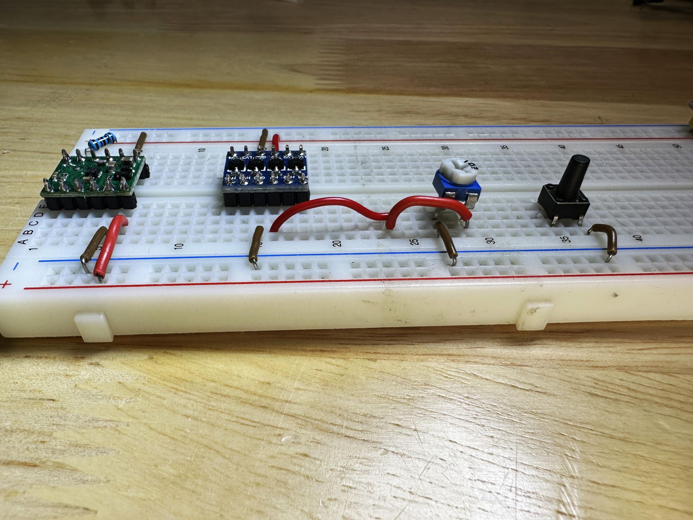
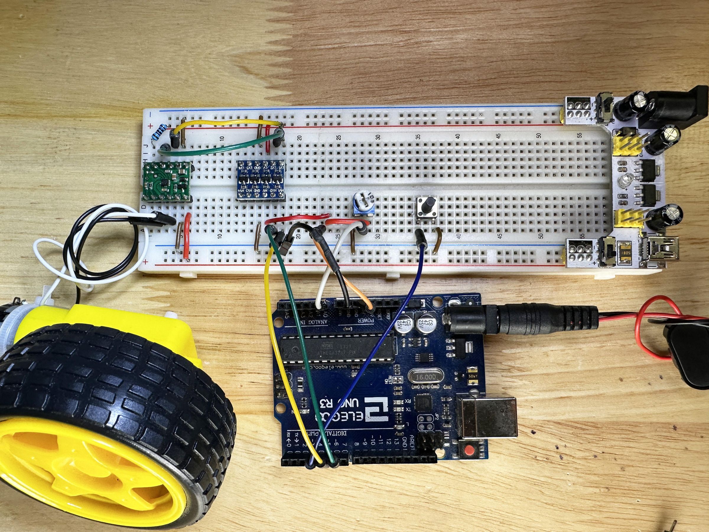
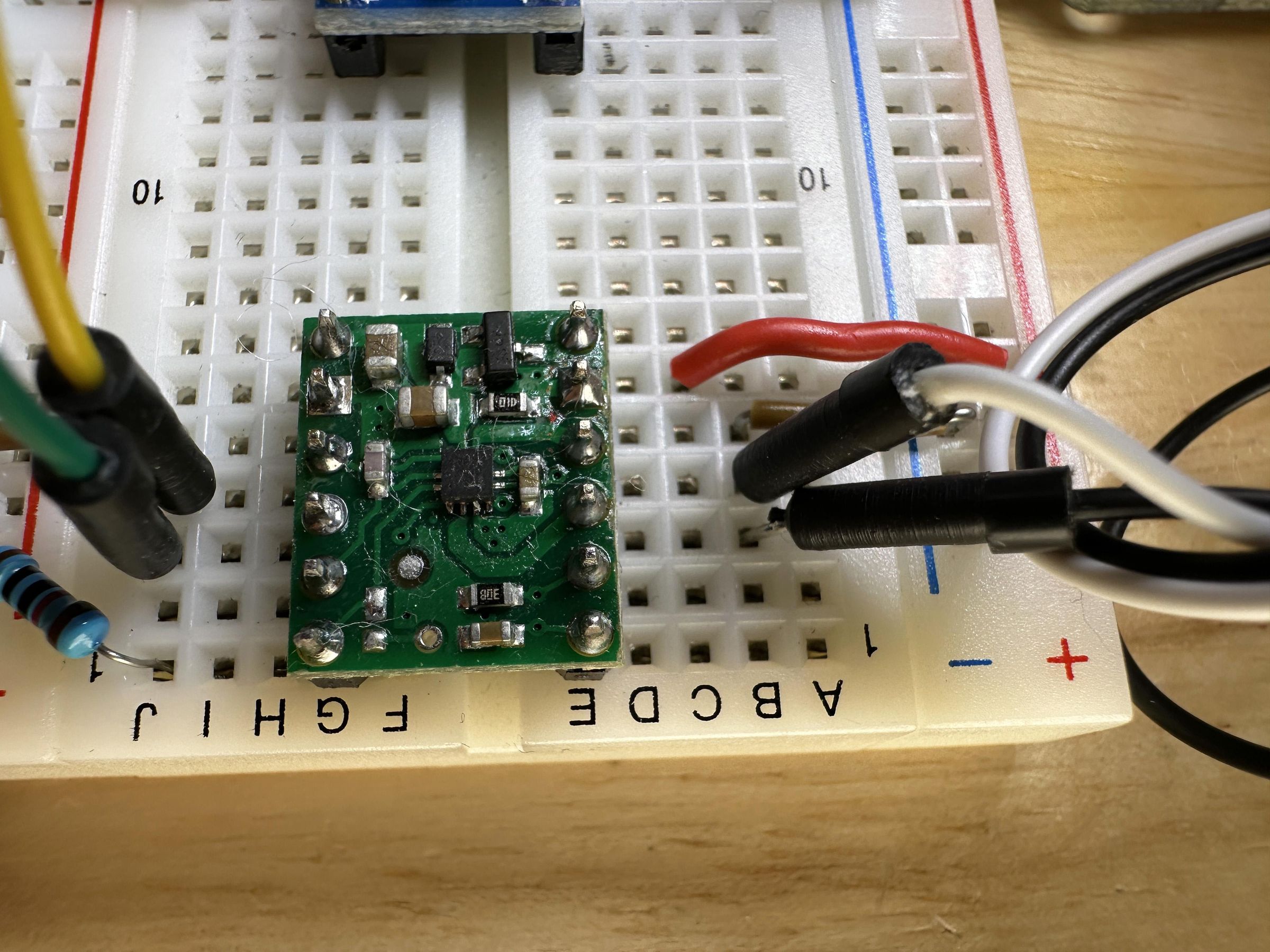
I have included a drawing of the circuit at the end of this step as well as photographs so you can copy the circuit and try the motor controller on your own. Please note, the UNO must have a ground connection to the breadboard. In the drawing, the left power rail has 3.3 volts from one side of the breadboard power supply. The 3.3 voltage is for the logic level converter so that the digital inputs to the motor driver are at this voltage. Furthermore, the sleep pin (pin 6) must be pulled up to this voltage with a 10 kOhm resistor. If you try the circuit and connect the sleep pin to ground, the H bridge within the motor driver will stop.
The UNO 5 volts is connected to the one outside pin of the potentiometer and to the high voltage pin (HV) of the logic level converter. These will therefor be compatible with the 5 volts of the UNO’s digital and analog pins.
The power rail on the right side of the breadboard has 5 volts, also from the breadboard power supply mentioned above. This is because the hobby motor used in this demonstration uses 5 volts. The only connection to this 5-volt power rail is the VIN pin (pin 12) of the motor driver. In the future, I will change this to 12 volts and use a 12-volt motor, so the VIN pin is the only thing connected to this power rail.
The push button is used to signal the microcontroller to change direction and the potentiometer is used as a dial to control the speed.
The 9-volt battery is used to power the UNO. I don't want to connect the circuit to my computer just in case.
The Arduino Code
I wrote the code in the Arduino IDE. It is very simple on purpose so that if anything does not work as intended, then I know it is not likely to be because of the code.
The first section is all commented out, but I use that portion to explain to myself what the code will do and what connections to make. I do this out of habit as I sometimes start and stop projects and have to remind myself what the connections were. Or I find it useful if I use the code in the future for a different project and save myself time.
Then in the code, I name the pins for the pulse wave modulation (PWM) that will be the inputs to the motor driver. I also name the pin for the push button.
In the set up, I declare the output or input functions of these pins. The pin for the push button (dirButton) is a pull up so that within the UNO, the defalt will be a digital 1 (HIGH). Then when the button is pushed, which connects the pin to ground (0 volts), the signal will be a digital 0 (LOW).
In the loop function, the UNO will make an analog reading of pin “A0” and store this value as an integer named “val”. The UNO will scale the reading from 0 to 1023 because it is recorded as a 10-bit number. The in the second line of the loop, val is scaled to an 8-bit number named pwmVal. This is because the UNO’s PWM pins are based on an 8-bit number. Eight-bit integers range from 0 to 255. These two lines of code are:
int val = analogRead(A0);
int pwmVal = map(val,0,1023,0,255);
After this, there is an “if/else” section that will control the speed and direction. The direction is dependent on the value of “directionToggle”. If this is a digital 1, meaning TRUE, then “if” portion of the code is run. However, if directionToggle has the value of 0, meaning FALSE, then the “else” portion of the code is run. In both portions, one PWM pin is cleared to zero (LOW), and the other PWM pin is modulated based on the value of pwmVal. Then there is a 10 millisecond pause, which is a little arbitrary. This if/else section of the code looks like this:
if (directionToggle) {
digitalWrite(pwmPin2,LOW);
analogWrite(pwmPin1,pwmVal);
} else {
digitalWrite(pwmPin1,LOW);
analogWrite(pwmPin2,pwmVal);
}
delay(10);
The last section of the loop function poles the value of the push button pin. Normally, a digital reading of this pin will be HIGH because of the internal pullup. However, when the button is pressed, the reading will be LOW. If a press is detected, then both PWM pins are cleared (LOW) and the value of directionToggle is changed, from zero to one, or one to zero. The code then causes a 1000 millisecond delay. This pause allows the motors to slowdown, and it also gives the operator a full second to remove their finger from the button. A shorter delay would most likely result in the UNO detecting the button press several times and responding as if there were multiple button presses. This last section of the code looks like this:
if (digitalRead(dirButton)==LOW) {
digitalWrite(pwmPin1,LOW);
digitalWrite(pwmPin2,LOW);
directionToggle = !directionToggle;
delay(1000);
}
Downloads
Conclusion and Links to More Information
Here is more information about the Pololu MP6550 Motor Driver Carrier:
https://www.pololu.com/product/4733
I am pleased that I was able to get this circuit and code working since I have never used this motor driver before. I am confident that I will be able to use the motor driver for more advanced purposes. Please have a look at the YouTube videos in this Instructable to see the demonstration.
I am very comfortable with the UNO, so I chose to use that for my experimentation. This meant using the logic level converter, which was an extra step. However, in the future I will probably use 3.3volts with either a bare ATMEGA microcontroller (not the UNO with all the supporting components) or an ESP32. Then I will not need the converter. Furthermore, if I make a remote-controlled project, as I intend to do in the future, then the nRF24L01 also runs on 3.3volts anyways.
In the next video I plan to use the same circuit and code, but change to a 12-volt motor and power it with a 12-volt lead acid battery I have lying around. I am hoping for a lot more speed and torque with that. If you are interested in that, then please check out my YouTube channel.
If you finished this Instructable, please leave a comment. Anything really, it is just nice to hear from you. Thanks for reading. 😊