The Brownstone Clock — a Modern Take on the Berlin Set Theory Clock
733 Views, 4 Favorites, 0 Comments
The Brownstone Clock — a Modern Take on the Berlin Set Theory Clock
.png)
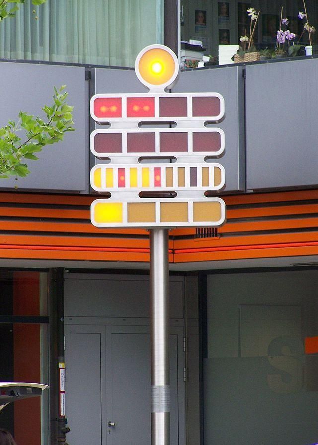
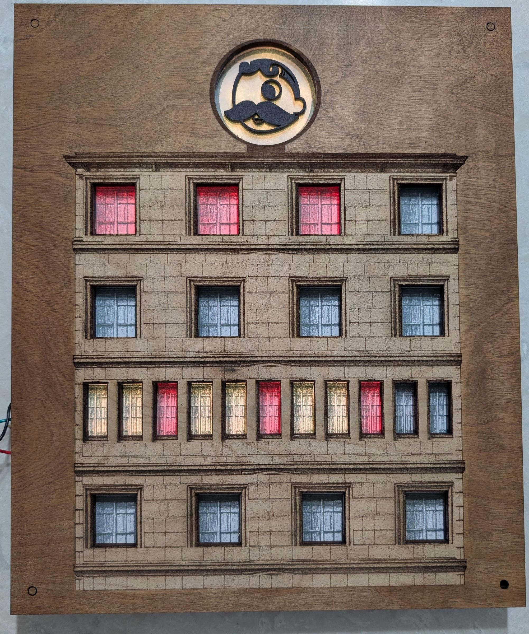
In 1975 a clock was installed in Berlin, Germany that most people walk right past without ever realizing it tells time. No hands, no numbers, no display. Just rows of colored lights on what looks like an abstract art installation. It is called the Mengenlehreuhr — the Set Theory Clock — and once you understand how it works, you cannot stop seeing it.
The idea is elegant. Four rows of lamps, each lamp representing a value. You add them up to read the time. Top row counts five-hour blocks. Second row counts single hours. Third row counts five-minute blocks. Bottom row counts single minutes. Light the right combination and you have the time. It is mathematics made physical, and it is deeply satisfying once it clicks.
I had been experimenting with LED matrix clocks for a while — a word clock, a weather display, various iterations — when the thought hit me: a building facade and a set theory clock are the same thing. Windows that light up. Rows that mean something. The Mengenlehreuhr was not designed to look like a building, but it might as well have been.
That realization became this project. The Brownstone Clock is a Berlin Set Theory Clock wearing the skin of a classic New York brownstone apartment building. The lit windows tell the time. The building is the clock face. And the best part is that the building is just a skin, it can be made into whatever you wish. I must give credit to La Fabrique DIY for the binary clock featuring a building facade which became my inspiration.
How the Mengenlehreuhr Works
Before building anything it helps to understand what you are building. The Berlin Set Theory Clock tells time through four rows of lamps. Here is how to read it:
● Top row — 4 lamps, each worth 5 hours. Two lamps lit = 10 hours.
● Second row — 4 lamps, each worth 1 hour. Three lamps lit = 3 hours.
● Third row — 11 lamps, each worth 5 minutes. Seven lamps lit = 35 minutes.
● Bottom row — 4 lamps, each worth 1 minute. Two lamps lit = 2 minutes.
To read the time, add each row. Two lamps on top plus three on the second row = 13 hours. Seven lamps on the third row plus two on the bottom = 37 minutes. The time is 13:37.
On the original Berlin clock, the third row uses yellow lamps for most positions but red lamps at positions 3, 6, and 9 to mark the quarter hours — 15, 30, and 45 minutes. There is also a single lamp at the very top that blinks on and off every two seconds, a seconds indicator.
Now you know how it works, and if you are interested in building it, please continue. Please note you do not necessarily need a laser cutter to make this project. there are 3 different paths one could take in fabricating the building face as outlined below.
Supplies
Electronics
- ESP32 development board (any standard 38-pin dev board)
- WS2812B LED strip — enough for a 13×16 grid (208 LEDs minimum). Density of 60 LEDs per meter works well.
- 5V power supply — 2A minimum for this brightness, 4A for headroom
- Sheet for LED backer — 1/8 inch thick works well approx. 10"Wx12"H. (See Step 2.)
- Hookup wire, solder, soldering iron
- USB cable for programming
For the Diffusion Layer
- Corrugated cardboard — single or double wall approx. 10"Wx12"H
- Craft knife or box cutter
- Cutting mat
- Regular white printer paper
- Tape
- Laser cutter
For the Face (choose your path)
- Path 1 — Paper only: color print, b&w print, plain paper, poster print, your own hand drawing, etc.
- Path 2 — Sculpt it: cardboard, paper mache, popsicle sticks, craft knife, paint, texture materials
- Path 3 — Laser cut: access to a laser cutter, your choice of plywood, wood stain
- Path 4 — 3D print: go ahead and print a facade or whatever else you want
Tools
- Drill or laser for mounting holes, or even picture hanging brackets
- I have even used hot glue to glue the layers together
- Computer with Arduino IDE installed
Create LED Grid
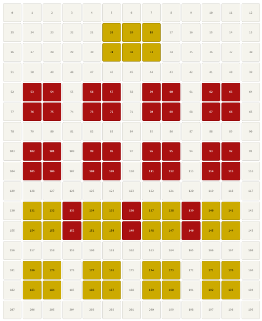
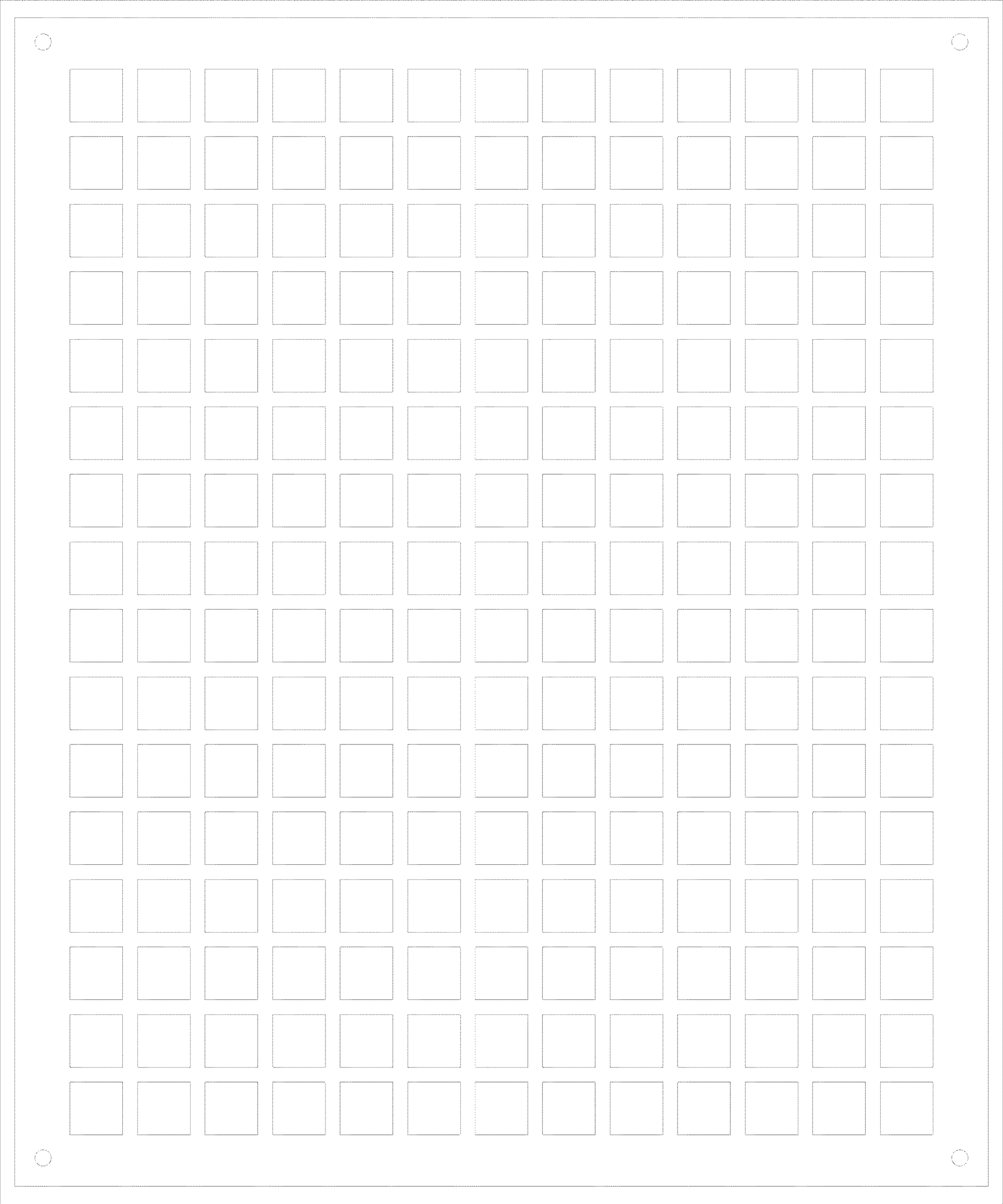
The foundation of this entire project is a 13-column by 16-row grid of individually addressable LEDs. That is 208 LEDs total. Each LED is a single WS2812B pixel capable of displaying any color.
The strip is wired in a serpentine pattern — sometimes called a zigzag or boustrophedon layout. Row 0 runs left to right. Row 1 runs right to left. Row 2 runs left to right again. This pattern continues for all 16 rows. This is important because the code has to account for the direction of each row when calculating which physical LED corresponds to which grid position.
Not all 208 LEDs are used to display clock information. The clock uses specific groups of LEDs arranged as lamps. The rest are simply off. This gives you a lot of flexibility — you can use the unused LEDs for other purposes or simply ignore them. I happen to have had a 13x16 matrix for another project so I used that.
Before soldering anything, plan exactly where your LED groups will sit in the grid. For this clock the lamp positions were chosen to match the window positions on the building facade design. The two have to align or the windows will not light up correctly.
Here is the lamp layout for this build:
- Seconds indicator — 6 LEDs clustered in the upper center of the grid, behind the circular medallion
- 5-Hour row — 4 lamps, each made of a 2×2 block of 4 LEDs, spread across the grid
- 1-Hour row — 4 lamps in the same 2×2 arrangement one section below
- 5-Minute row — 11 lamps, each just 2 LEDs tall and 1 LED wide, spanning the full width
- 1-Minute row — 4 lamps in the same 2×2 arrangement at the bottom
If you are designing your own facade the key constraint is that the lamp positions in your code and the window cutout positions in your face layer have to match exactly. Sketch both out on paper before committing to either.
Downloads
Prepare the LED's
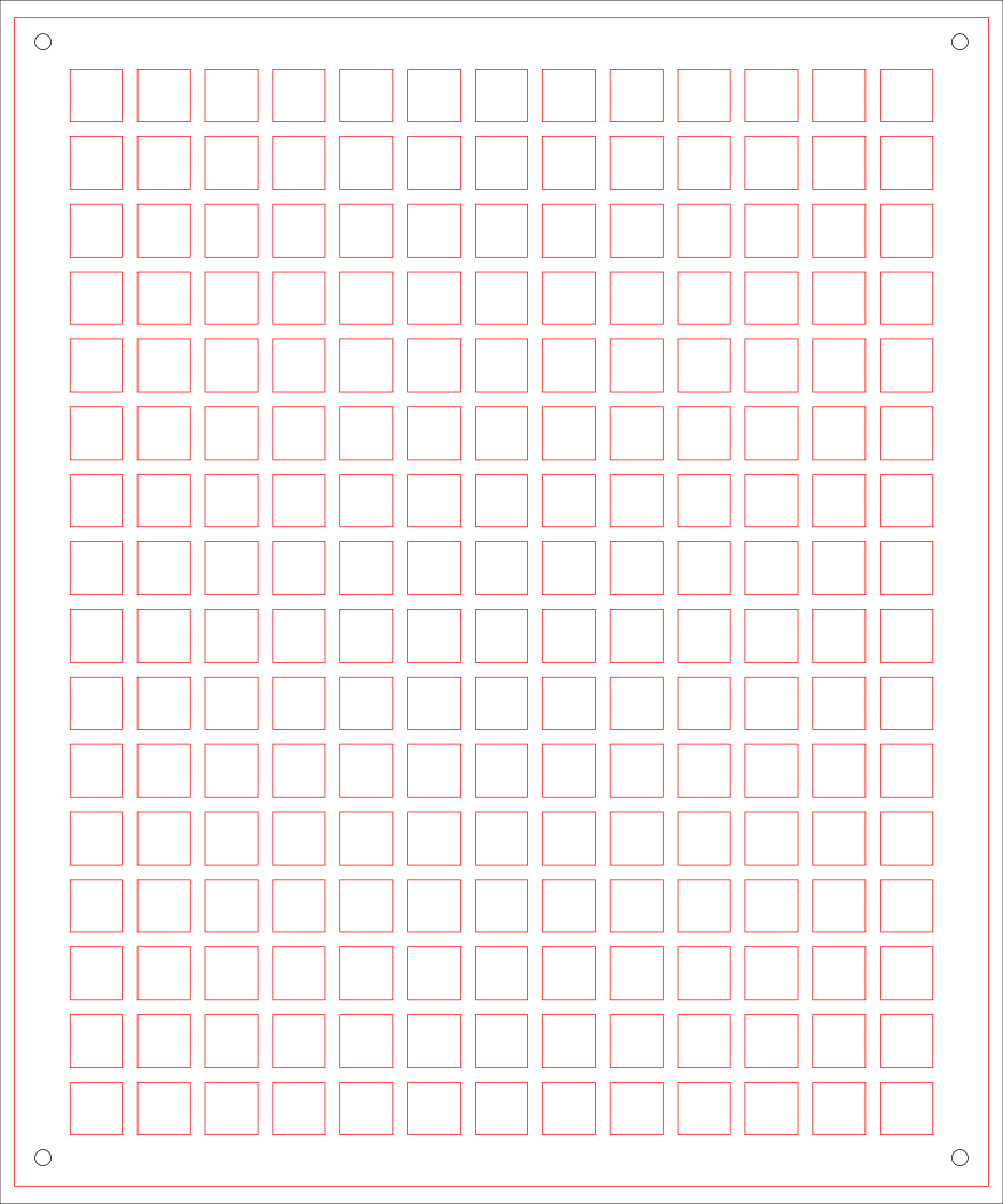
Cut your MDF or sheet of whatever to the size of your finished clock face. This board serves as the structural foundation that everything else attaches to. It also gives the LED strip something solid to adhere to. I used 1/8" MDF however, you could used heavy cardboard, foam board, acrylic, plastic, etc. Attached is the grid pattern I used.
Mark out your grid on the board — 13 columns and 16 rows. You do not need to mark every LED position, but marking the rows helps keep the strip straight when you are sticking it down.
Drill any mounting holes now before the LEDs are in the way. Four holes in the corners work well for hanging or for screwing the backer to a frame.
WS2812B strip comes in a continuous reel. You cut it to length at the marked cut points between LEDs — never in the middle of an LED or you will damage it. Each row of 13 LEDs needs its own cut strip.
Starting at the top left, place row 0 left to right. Cut, then place row 1 right to left — this is the serpentine pattern. The data line flows continuously from one row to the next so the direction matters for the wiring.
At the end of each row you need to solder a short wire connecting the data out of that row to the data in of the next row. Keep these connection wires short and consistent in length. Also connect power and ground across all rows — do not rely on the data wire alone to carry power through the whole strip.
Wiring
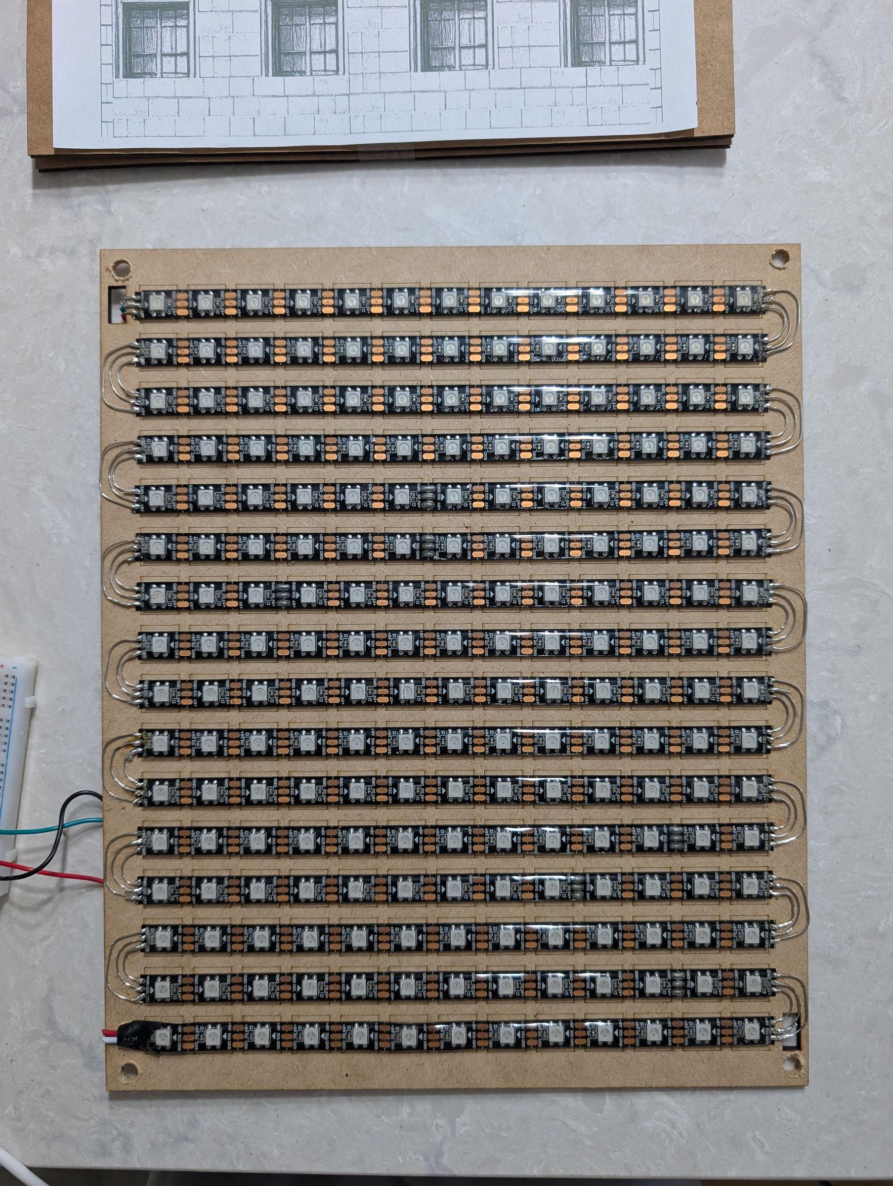
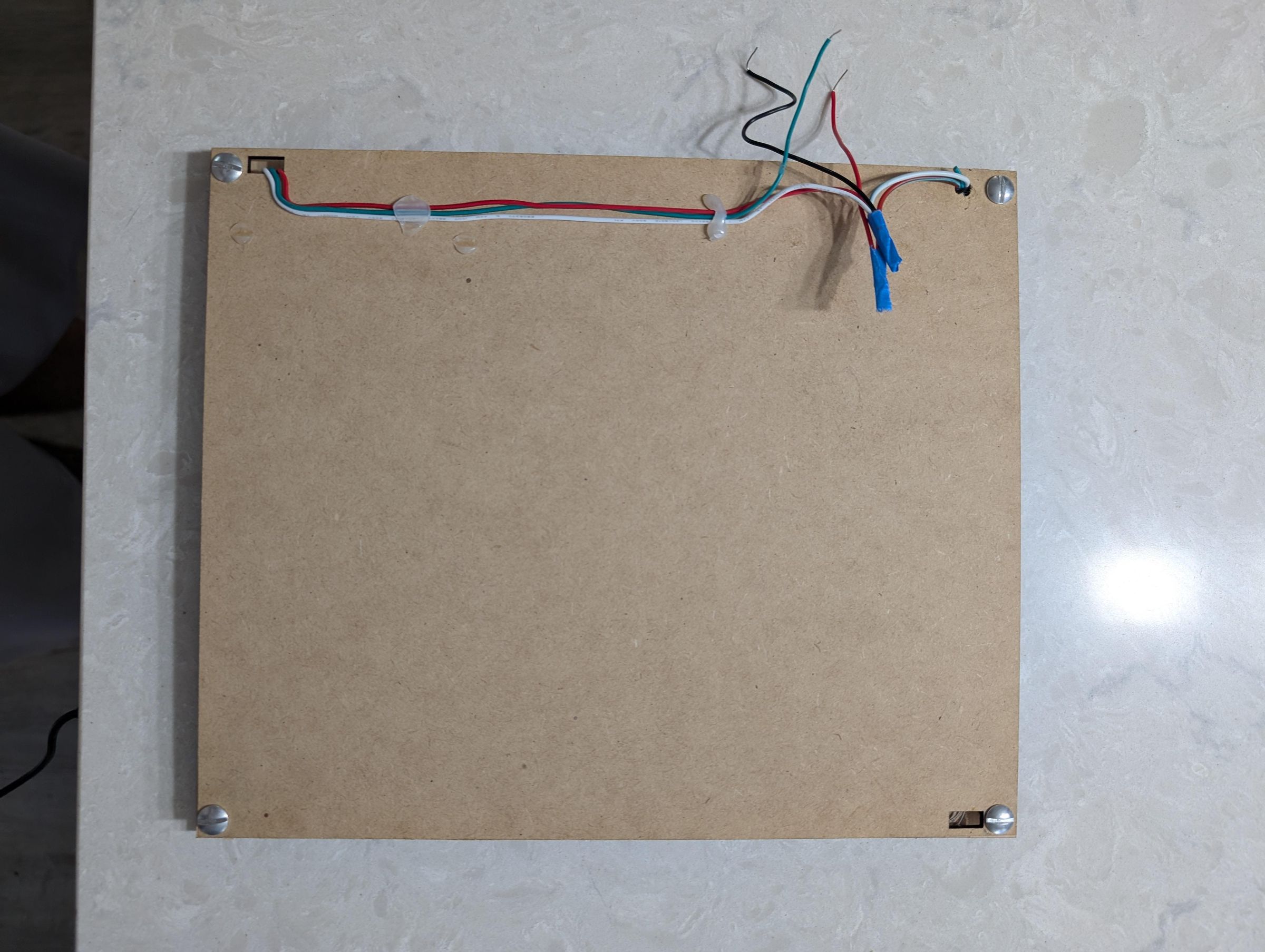
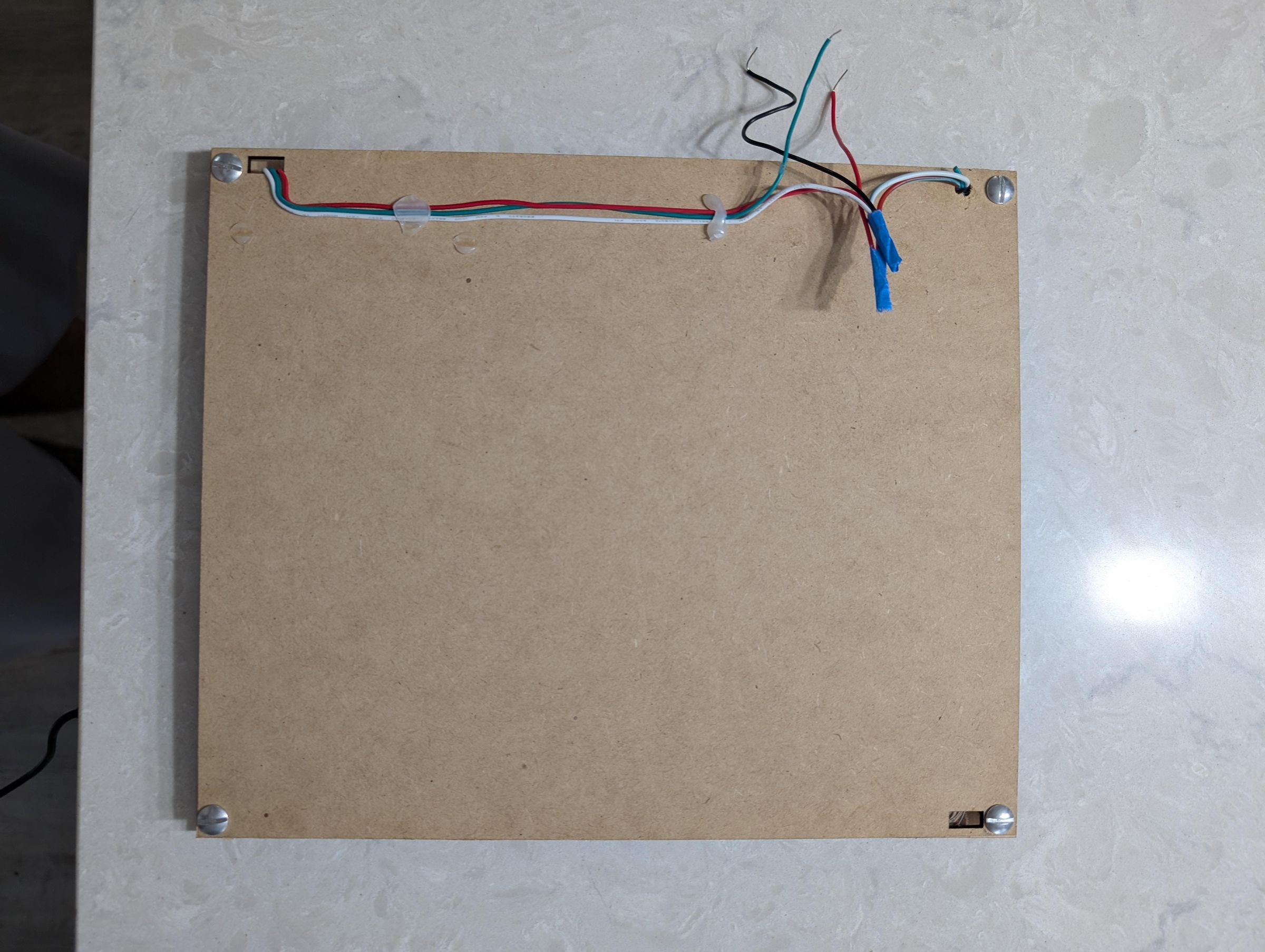
The LED strip needs 1 connection to the ESP32: data. Connect the 5V and ground from your power supply directly to the strip AND to the ESP32— do not route power through the ESP32 board as it cannot handle the current draw.
The data line from the beginning of the strip (LED 0, top left) connects to a GPIO pin on the ESP32. In the provided code this is GPIO pin 5. You can change it in the code if your wiring dictates a different pin.
Connect the ground from the power supply to a ground pin on the ESP32 as well. This common ground is important — without it the data signal will not work correctly.
A 300-500 ohm resistor in series on the data line is good practice to protect against signal reflections. A 1000 microfarad capacitor across the power supply leads helps smooth out current spikes when many LEDs switch on at once. I personally did not use either of these and so far have noticed nothing.
Before you do anything else, upload a test sketch and make sure every LED works. It is much easier to fix wiring problems now than after you have built the enclosure around it.
The test sketch should run through a few simple animations — a color wipe in red, green, and blue to confirm color channels work, a row-by-row sweep to confirm the serpentine wiring is correct, and a chase animation to individually verify each LED. If a row lights up in the wrong direction, the serpentine order of that row is reversed in your wiring and needs to be corrected.
See step 8 Tip about wiring in the ESP32.
Downloads
Designing the Facade or Face
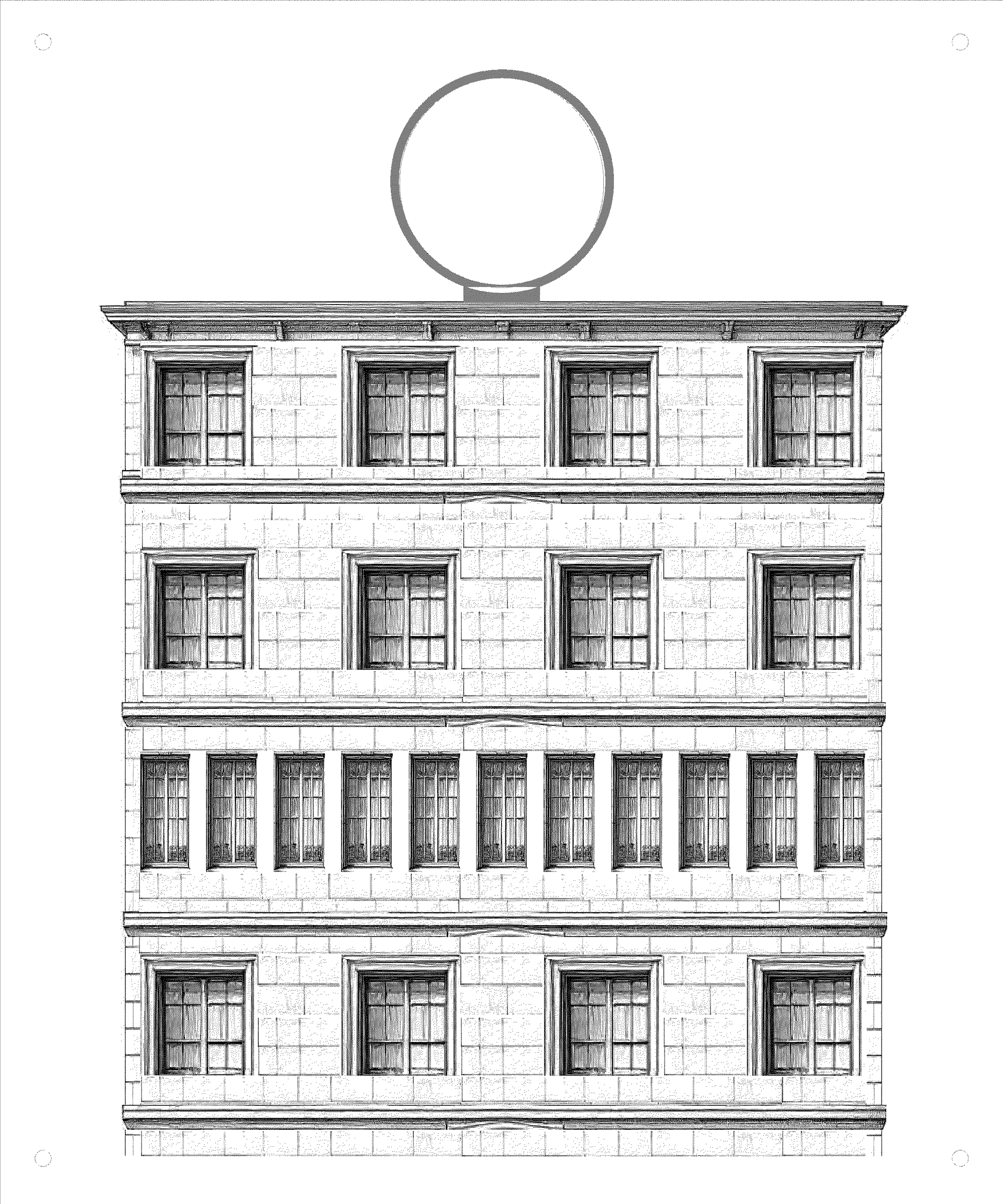
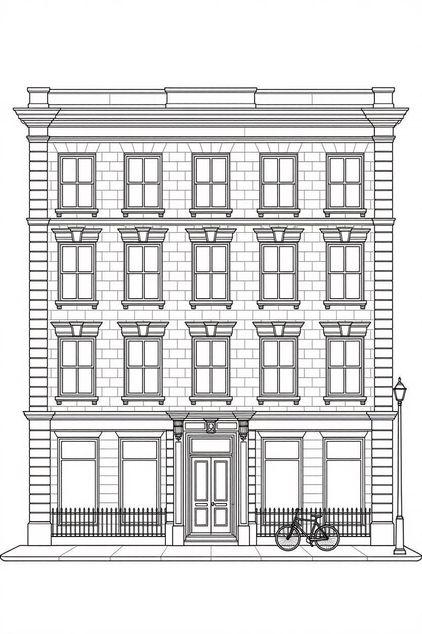
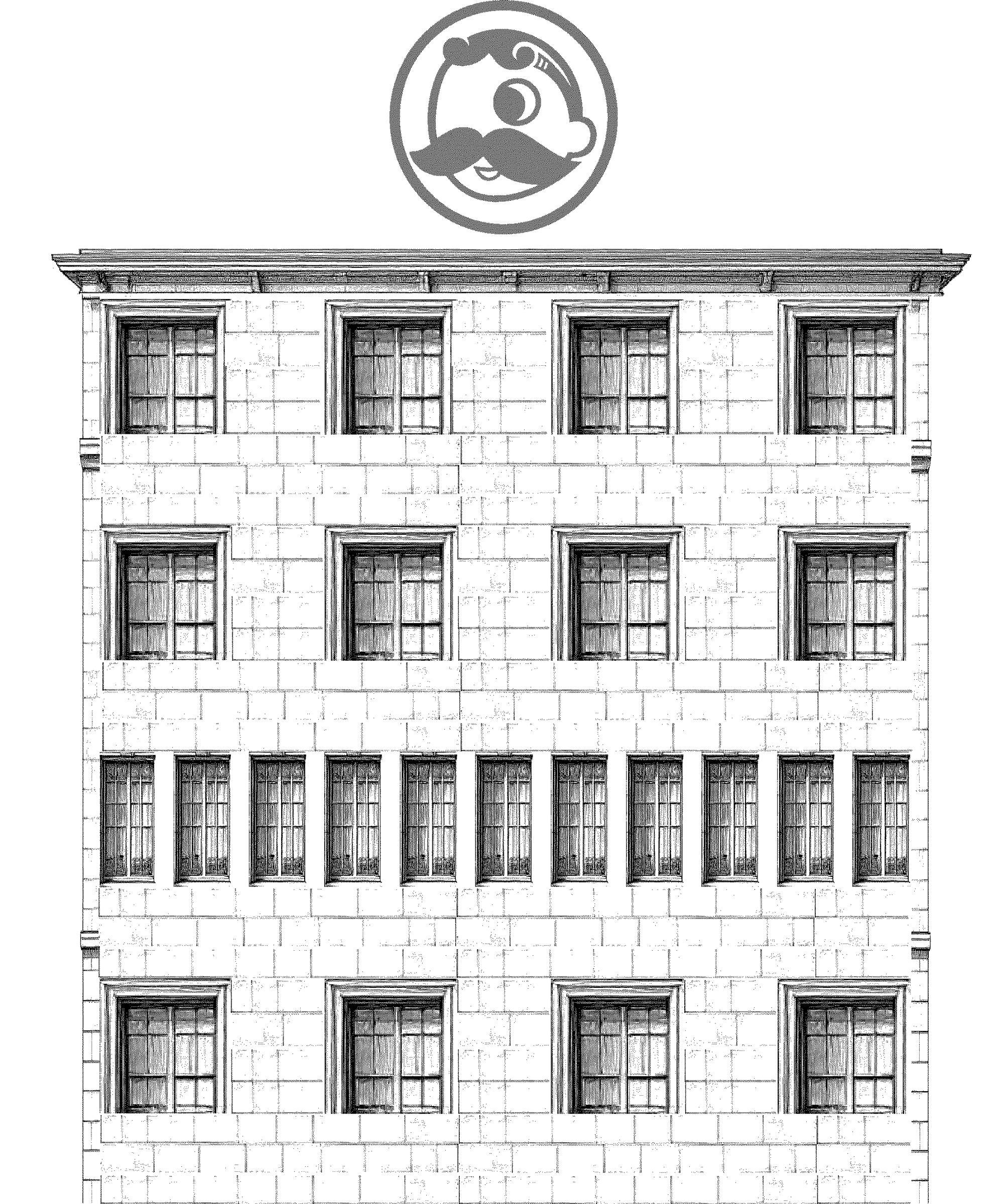
This is where the project becomes personal. The building facade is just a design — it can be any architectural style you want. A classic New York brownstone, a Georgian townhouse, a Victorian row house, a modern apartment block, even a lighthouse or barn. The only requirement is that it has windows, or openings, in the right positions to align with your LED lamp groups. I have attached a photo and 2 svg files of a clean building facade that could serve as your starting point.
*Tip- I asked an ai program to draw me a simple NY style brownstone apartment line drawing. That is what is attached.
Start with a reference image of the architectural style you want. Trace or redraw it so that the window positions line up with your LED lamp groups. The windows do not need to be the same size as the LED groups — in fact making the window openings slightly smaller than the LED group behind them gives a cleaner, more defined light effect.
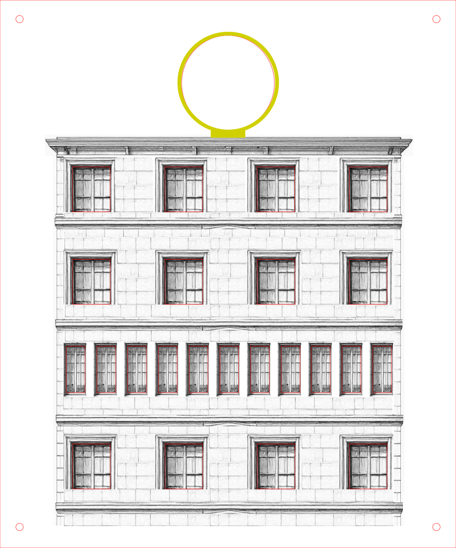
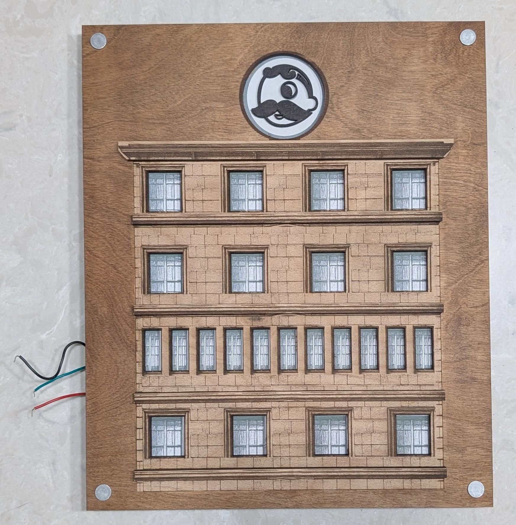
For this build the design was created digitally and sent to a laser cutter. The file included the overall facade shape, the window openings, and decorative details like cornices, brick texture, and window frames. The circular medallion at the top was designed as a separate removable piece.
Your method will be different than mine, unless you are following along with my build. I do not have a paid version of any photo editing software or apps so I improvised. I simply imported an image of a building into lightburn. From there I just traced the outline of a window and applied a mask. what this does is keeps any part of the image within the outline and hides everything outside of the outline. What I ended up with was just an image of a window. Once done I was able to easily change the size and shape of the window. I repeated this process for the bricks, cornice, and building trim. After I had all the "pieces" of the building, it was simply a matter of resizing and laying out all the parts to fit.
For different ideas jump to the where to go from here section.
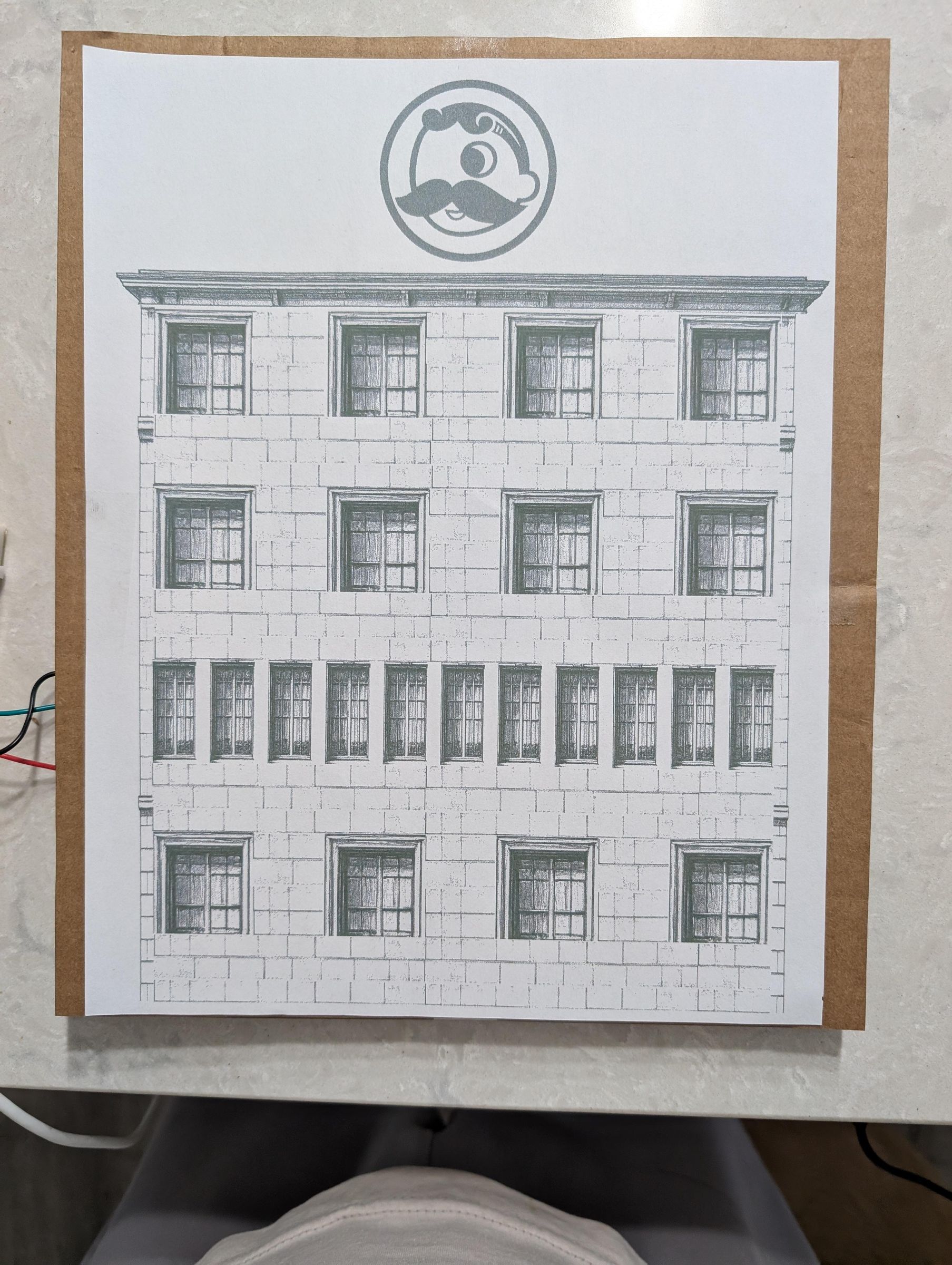
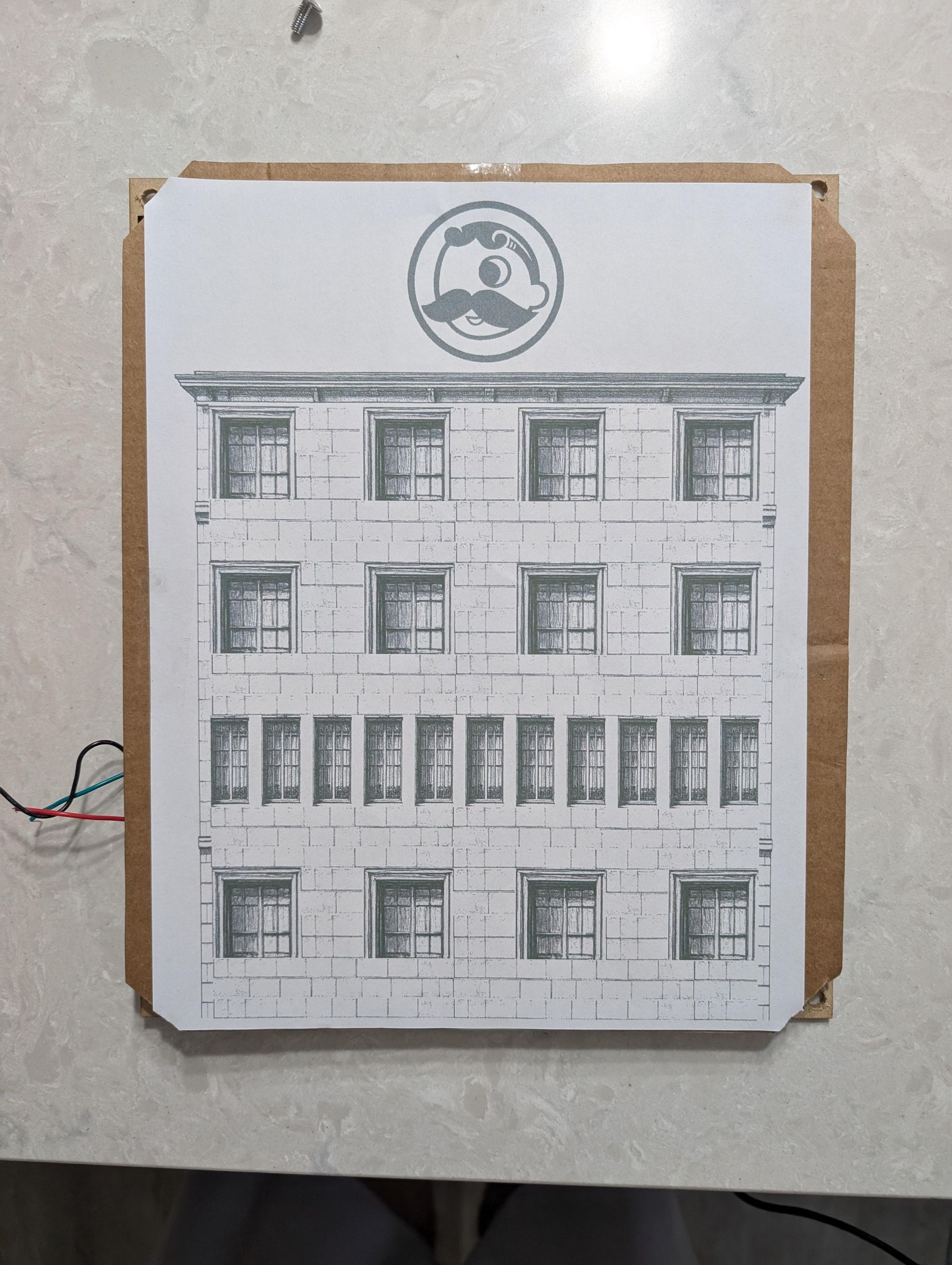
*TIP- Before cutting anything in wood or cardboard, print your facade design on regular white printer paper at full scale. This serves two purposes — it lets you verify the window positions align with your LED grid before you commit to materials, and it can actually serve as your finished face layer if you do not have access to a laser cutter.
Place the printed paper over your LED grid and power it on. Check that each lit LED group shines through the correct window. If anything is misaligned, adjust the design and print again. It costs nothing to iterate at this stage.
If you are going the paper-only route, this printed sheet could be your finished face. The light from the LEDs shines through the paper beautifully, giving a warm diffused glow that looks intentional. Mounting it in a simple picture frame completes the effect.
.svg)
.svg)
Diffusion Layer
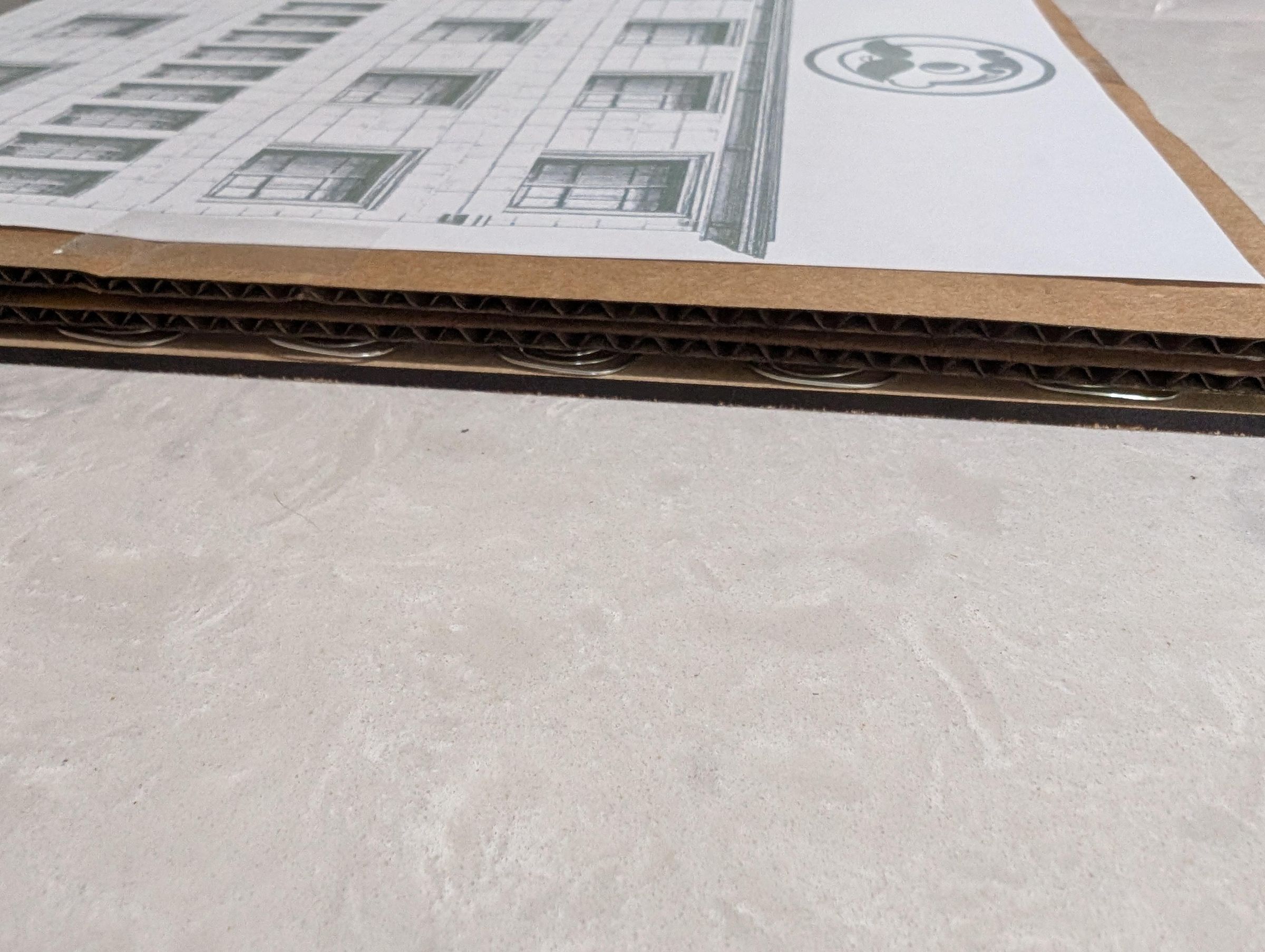
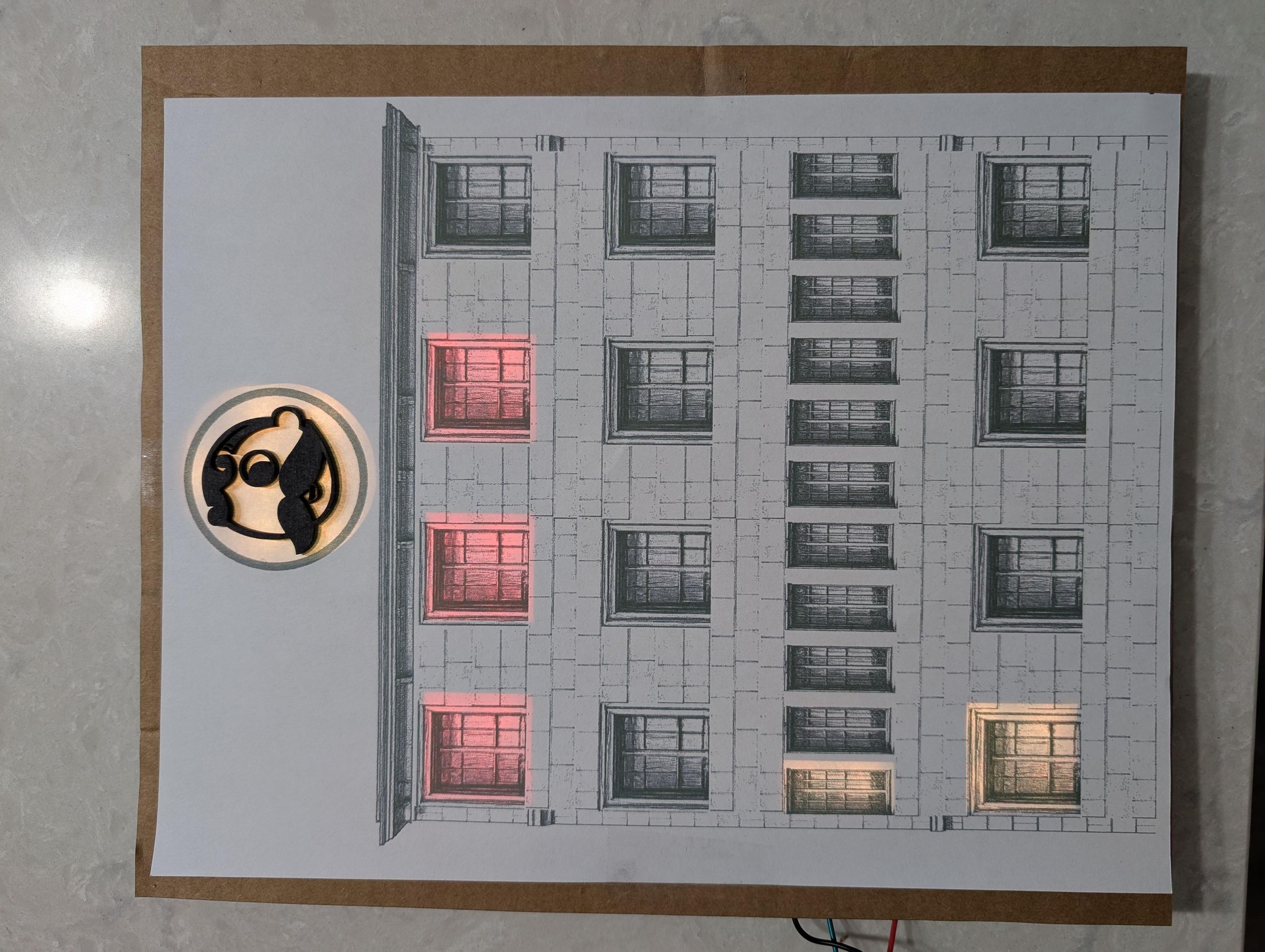
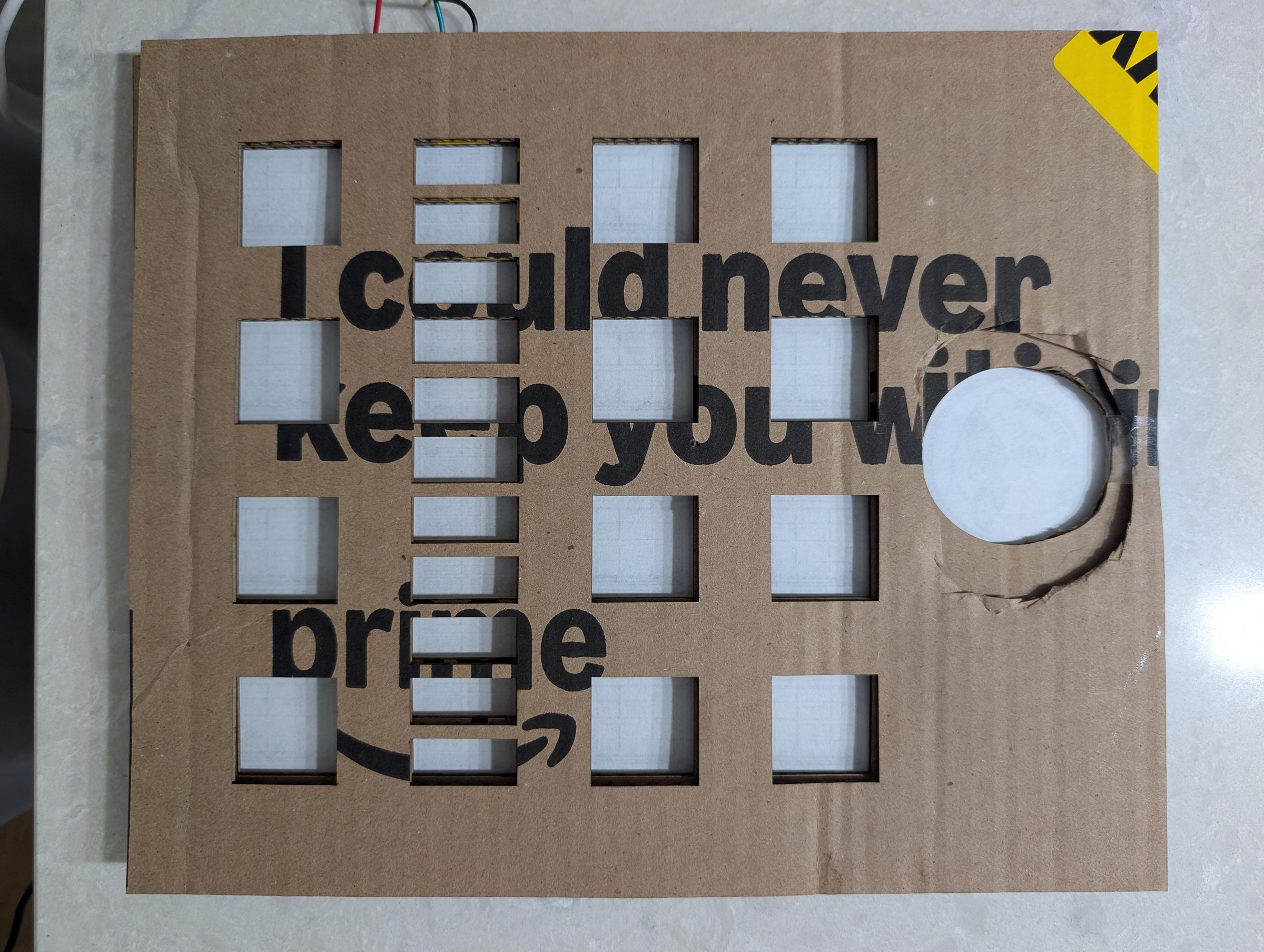
Once the face is finished you now have a template for the diffusion layer.
If you have ever looked at a word clock and the methods used to build a light box around each lamp, it can get a little crazy and bulky. Luckily there is a simpler way.
The single most important trick in this build is the cardboard diffusion layer, and it costs nothing. Without it, each LED shows as a bright individual dot — a hotspot — rather than a soft even glow filling the window. The cardboard layer fixes this by creating physical separation between the LED and the face.
Cut a piece of cardboard the same size as your backer board. Then cut rough openings where each LED lamp group sits. The key word is rough — make these openings larger than the actual window openings in the face layer above, you'll thank yourself later. This oversizing allows the light from multiple LEDs to spread and blend before it reaches the face, eliminating hotspots and under filling. Let the face layer dictate the actual opening size.
Stack two layers of cardboard if you need more depth. The more space between the LED and the face layer, the better the diffusion, but the brighter you need to make the led's. For this build two layers of standard corrugated cardboard gave the right effect. If you look at the original Berlin clock, it has massive hot spots. It's really up to you. With the 2 layers I used, I had no bleed over even in the closest windows, and the diffusion was even, enough.
Once the cardboard spacer is in place, tape your sheet of paper over the entire face of the cardboard. This paper layer is the actual diffuser — it scatters the light from each LED group into a soft, even glow.
Regular copy paper works perfectly. Do not use anything too thick or the light will not come through well enough. Do not use anything translucent like vellum or tracing paper — it transmits too much and you lose the diffusion effect.
Making the Facade or Face
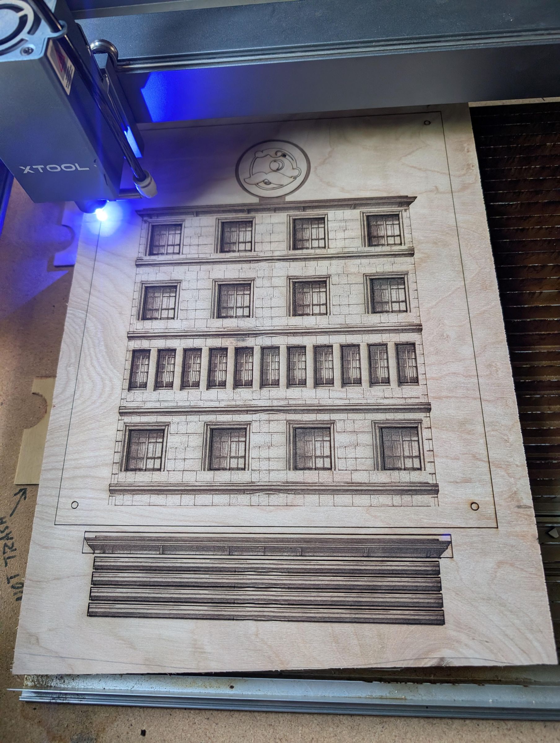
Now choose your face layer path. There are three good options depending on your tools and ambition:
Option A — Paper Print (no tools required)
Your paper printout from Step 4-5 is your face. Mount the LED backer with its cardboard and paper diffusion layers in a picture frame, then place your printed facade design in front. Done. This looks surprisingly good and is a legitimate finished result. You could use markers, paint, or colored pencils if your artistic.
Option B — Cardboard Sculpture
Cut a facade shape from sturdy cardboard — double-wall corrugated works best. Cut precise window openings where the LED groups sit. Build up architectural details using additional cardboard strips and shapes: cornices, window frames, door surrounds, brick courses. Paint and texture to taste. This path rewards craft skills and produces a uniquely handmade result.
Option C — Laser Cut Wood
Design your facade in vector software and cut it from whatever you want or have on a laser cutter. The laser can engrave surface details like brick texture, window frames, and decorative moldings in the same pass as the cutting. Sand lightly, apply wood stain, and finish with a clear coat. This path produces the most refined result.
Option D — 3D Print
Go ahead and try printing your own facade. I cannot help you here as I have no experience with 3D printing.
Building Sign?
You need something to fill in that big circle. Again, the design is totally up to you. I decided to give a nod to B-more and use the Natty logo. I encourage you to use your favorite sports team logo, character, symbol, monogram, the sky is the limit here. All I did was laser cut my logo, color it with a black marker, and used a THIN and SMALL amount of glue and glued it directly to the paper diffuser.
Assemble the Layers
At this point it should be fairly obvious how to assemble, but here are the steps anyway.
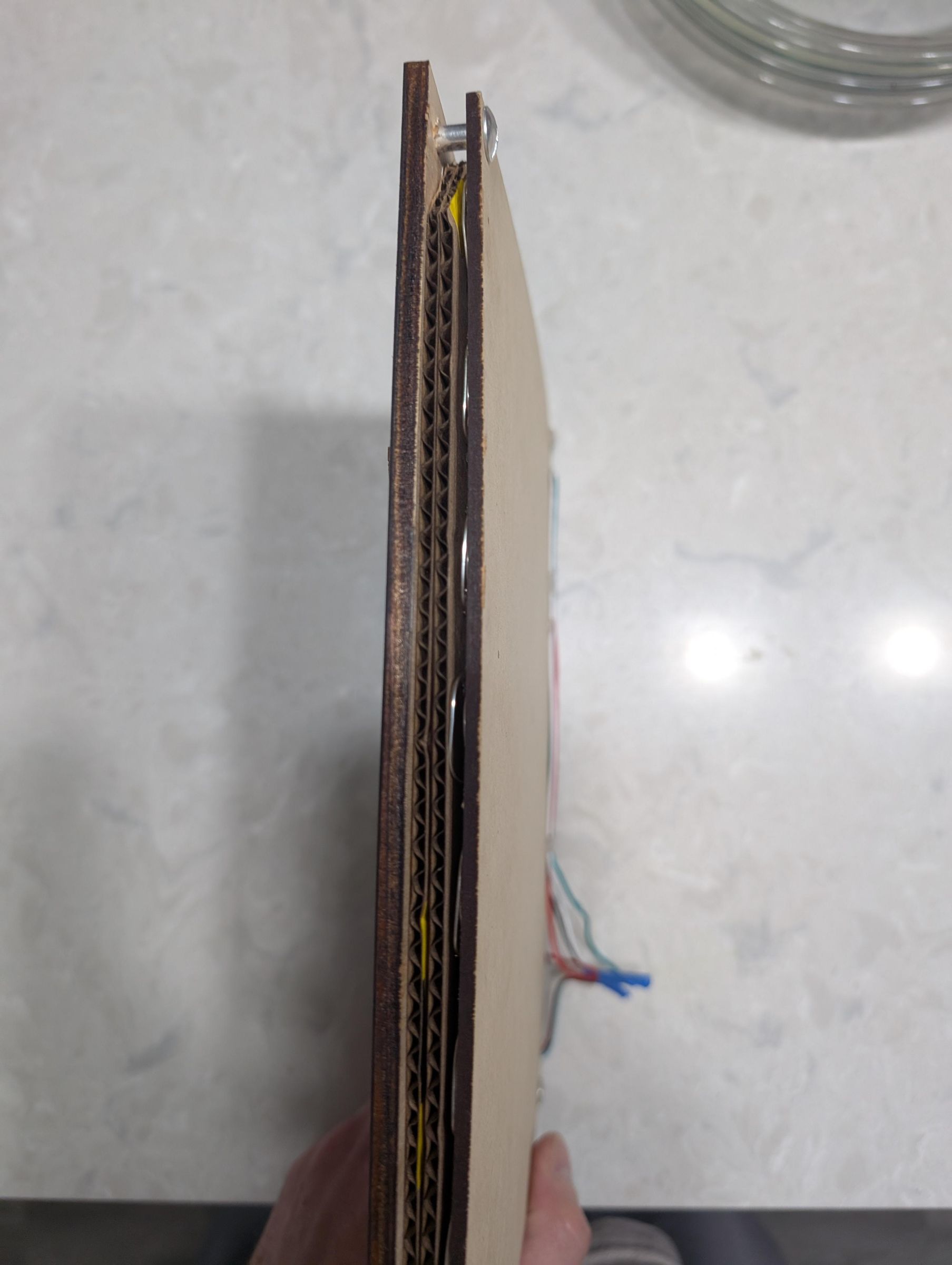
Working from back to front the stack is:
- 1. MDF backer board with LED strip attached
- 2. Cardboard spacer with oversized rough cutouts
- 3. White printer paper diffusion sheet
- 4. Face layer (paper, cardboard sculpture, or laser cut wood)
- 5. Medallion in the seconds position
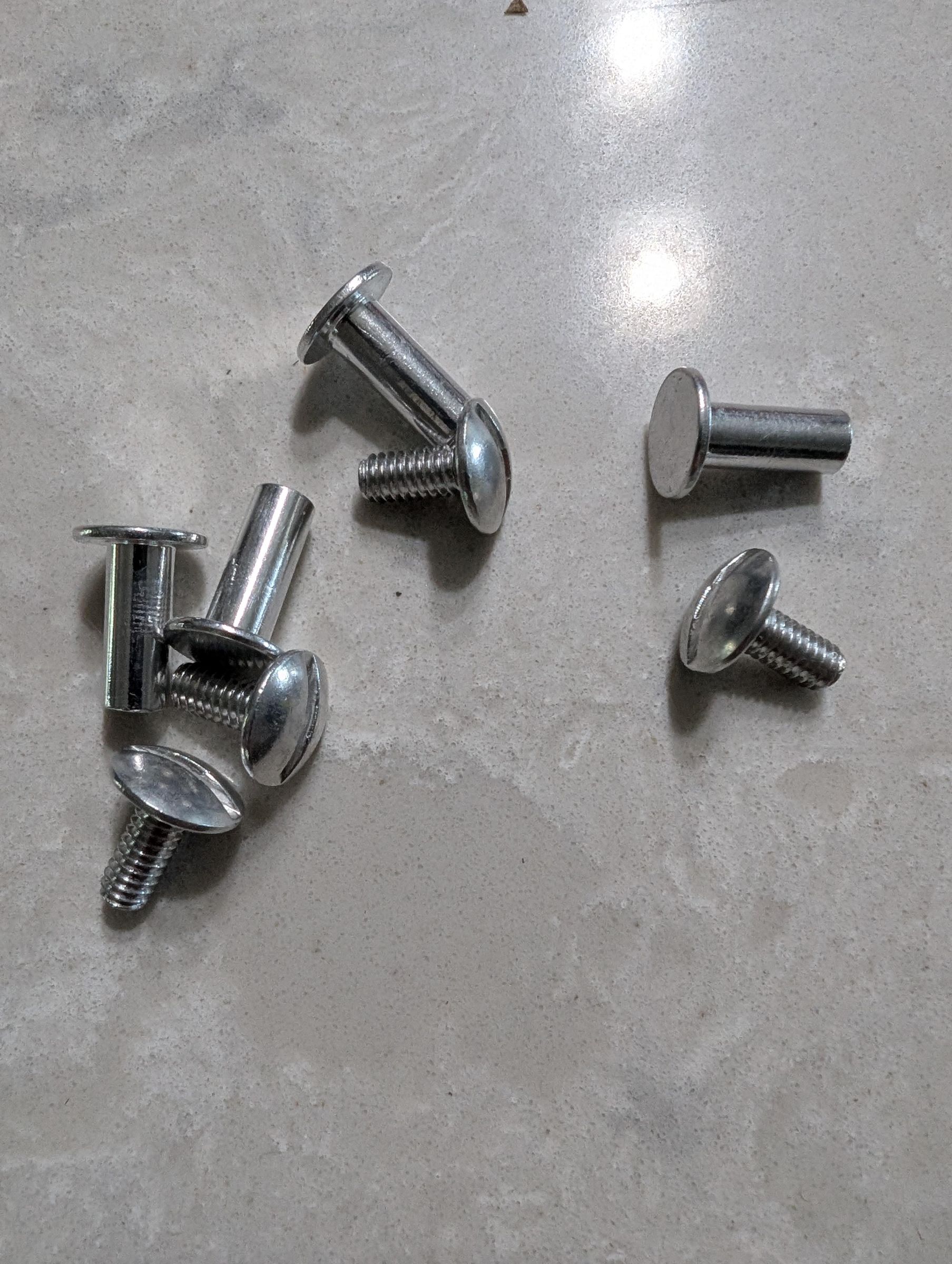
Align each layer carefully before fastening. The face layer window openings need to center over the LED lamp groups behind them. Once aligned, secure the layers together. Small screws through the corners work well for wood layers. Tape works fine for paper and cardboard. Hot glue works for both.
*Tip- I have holes in my led backer board and on the facade. trying to line up holes in the cardboard was difficult and it ripped the cardboard. The easiest way I found to assemble was to cut the corners of the cardboard away and just use the holes in the front and back panels. the screws will sandwich the cardboard tight between the layers and it will not move.
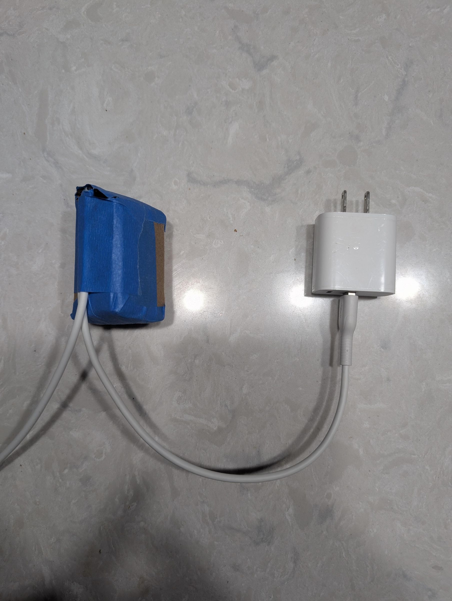
Route the power supply cable and the ESP32 USB programming cable out the back or bottom of the assembly. Leave enough slack to remove the ESP32 for reprogramming if needed.
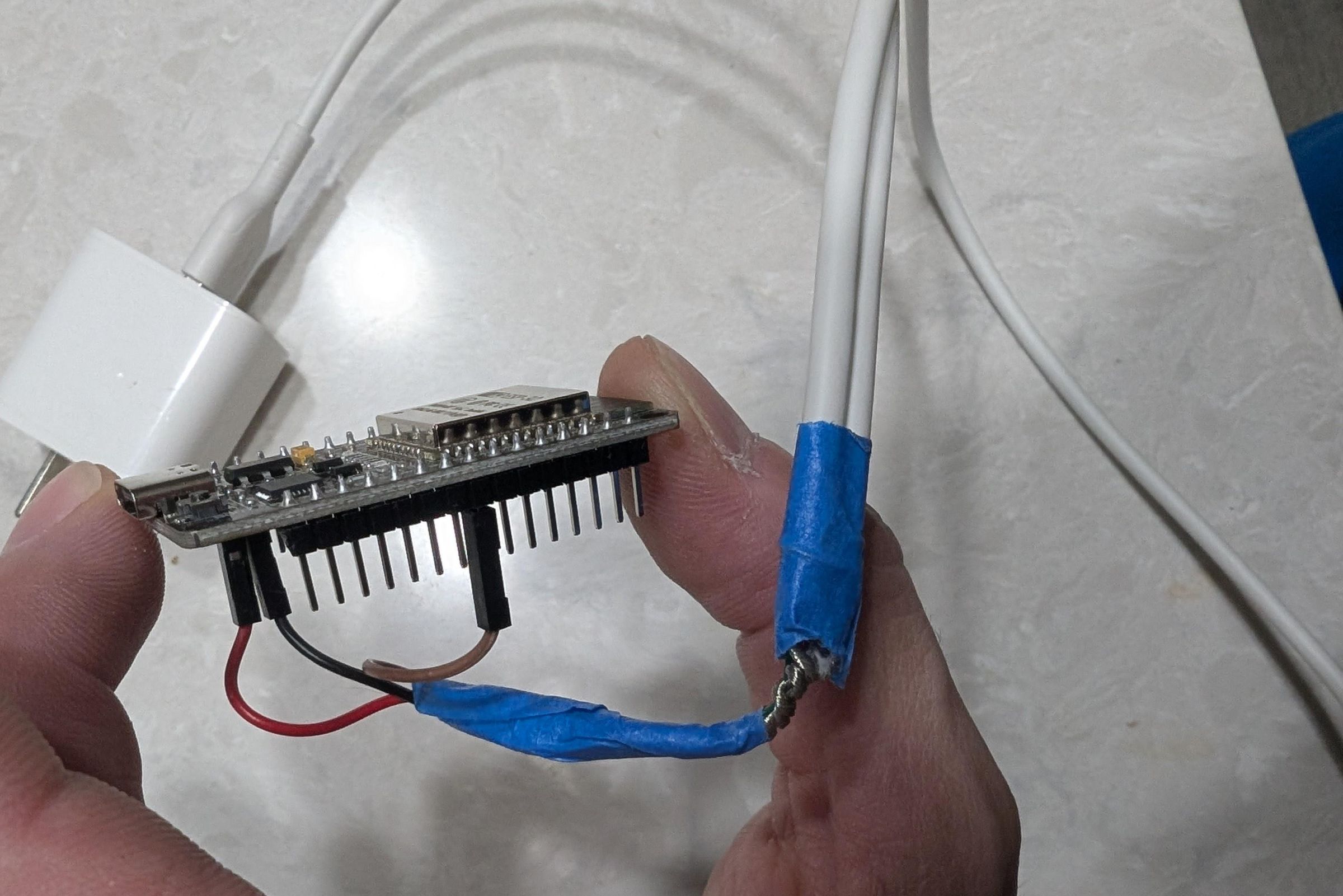
*Another Tip- I have found that since there are only 3 wires needed there is no reason to mount the electronics within the clock at all. This helps keeps the enclosure minimal. What I do is cut a 6' USB cable at 1 end and splice the power, ground, and data wire to the LED strip. At the other end I cut the USB end off and strip power, ground, data. on both ends of the cut. I will add another short length of wire to each of these and splice power, ground, and data wires each back together. now you should have 3 additional wires that will connect to the ESP32. Of course you could also use a small breadboard and glue it to the back of the clock. If you have any other tips or tricks please leave them in the comments.
Programming
The clock runs on an ESP32 microcontroller programmed through the Arduino IDE. If you have not used Arduino before, here is what you need:
- Download and install the Arduino IDE from arduino.cc
- In Arduino IDE go to File → Preferences and add this URL to the Additional Boards Manager URLs: https://raw.githubusercontent.com/espressif/arduino-esp32/gh-pages/package_esp32_index.json
- Go to Tools → Board → Boards Manager, search for ESP32 and install the Espressif Systems ESP32 package
- Install the FastLED library: Sketch → Include Library → Manage Libraries, search FastLED and install
- Connect your ESP32 via USB, select the correct board and port under Tools
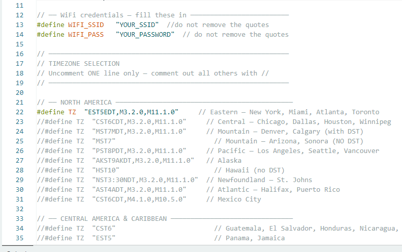
The provided code connects to your WiFi network, syncs the time automatically from an NTP time server, and displays the time on the LED grid in the classic Mengenlehreuhr format. It handles daylight saving time automatically and defaults to U.S. Eastern time and will resync once every day at 3am.
Open the sketch in Arduino IDE. At the top of the file find the configuration section and enter your WiFi network name and password. You also need to change the time zone to your location. I have tried to include all known time zones in the sketch so you just have to find your time zone and uncomment it. Be sure to only have 1 time zone uncommented. Upload to the ESP32. Open the Serial Monitor at 115200 baud to see the connection status.
On first boot you should see:
- WiFi connected
- NTP synced with the current time
- The clock display activating with the correct time
The startup animation sweeps through all the lamp positions so you can verify every LED group is working before the clock takes over.
Downloads
Reading the Clock Recap
Now that it is running, here is a quick reference for reading the time:
- Count the lit lamps in the top row and multiply by 5 — this gives the hours in multiples of five
- Count the lit lamps in the second row — add this number directly to the first row total
- Count the lit lamps in the third row and multiply by 5 — this gives the minutes in multiples of five
- Count the lit lamps in the bottom row — add this number directly to the third row total
- The medallion blinks every two seconds
Example: 2 lamps top row (10) + 3 lamps second row (3) = 13 hours. 6 lamps third row (30) + 4 lamps bottom row (4) = 34 minutes. The time is 1:34 PM.
It takes about a week of glancing at it before reading the clock becomes instinctive. After that you will find yourself a little smug about it.
Hang and Enjoy
Mount the clock on the wall using the corner holes, picture frame hardware, set it on a shelf, etc. The power supply can be hidden behind the clock or routed down the wall to an outlet. The ESP32 only needs power once programmed — no computer connection required for normal operation.
Once hung, the clock takes care of itself. It syncs time automatically and adjusts for daylight savings.
Where to Take It From Here
The building facade is just a skin. The LED grid behind it is a blank canvas. Here are some directions the community could take this:
Change What the Windows Display
- Color the windows based on outside temperature — blue for cold, yellow for mild, red for hot
- Show tide levels for coastal makers — windows fill like rising water
- Track air quality index with color gradients across the rows
- Display a sports score — each floor a quarter or period
- Build a family dashboard — each row tracks something different for each family member
- Out of the 208 LED's there are several that are unused. One could simply drill small random holes above the top of the building and turn on some LED's with twinkling and you just created a stary night.
- There is a row of unused LED's at the top, bottom, and sides. These could be used for auxiliary information so you do not mess with the clocks LED's.
Change the Facade
- A Victorian row house with ornate carved details
- A barn with hayloft windows
- A lighthouse — circular windows stacked vertically
- A cathedral with arched stained glass windows — colored acrylic inserts
- A modern glass tower — no diffusion, pure geometric light
- It doesn't even have to be flat. make it curved.
- Make it a 4 sided building with 4 clock faces
- Rows of car headlights on a parking lot
- The side of a cruise ship with all the windows would work
- Planes in the sky
- Think lights not windows or openings
Change the Materials
- No laser? Build the facade from layered foam board, paper mache, cardboard, clay
- Heck you could even hand draw something if you really wanted and have the ability
- Scale it up — a 3 foot version on a living room wall
- Scale it down — a desk clock version in a shadow box frame
- Resin cast the facade with embedded window frames
- Metal etching for an industrial look
Change the Medallion
- Your favorite sports team logo
- Family monogram or crest
- Business branding
- Seasonal swaps — pumpkin for Halloween, snowflake for winter
- Characters or symbols
- Any design you want
- You could even remove it entirely if you would like to save size or LED's
The code, the grid, and the diffusion trick are the foundation. Everything else is yours to invent.
A Note on the Code
The code provided with this Instructable is intentionally basic. It connects to WiFi, syncs the time, and displays that time in the traditional red and yellow. It is a starting point for you, not a finished product.
Changing LED colors, adding Bluetooth control, randomizing the fill order of the windows, adding weather data, adjusting the night mode hours — all of these are straightforward modifications for anyone who wants to dig into and modify the code. The FastLED library documentation is excellent and the ESP32 has more than enough power to do considerably more than this clock asks of it.
My first addition to the code was to add Bluetooth connection and commands. That way I could program the time, LED colors and brightness right from my phone without touching anything or plugging anything in.
If you build something interesting with this foundation, post it. The whole point of sharing this project is to see where the community takes it.