The Easy Way to Make a Coffee Table
by ICARUS in Workshop > Furniture
159 Views, 1 Favorites, 0 Comments
The Easy Way to Make a Coffee Table
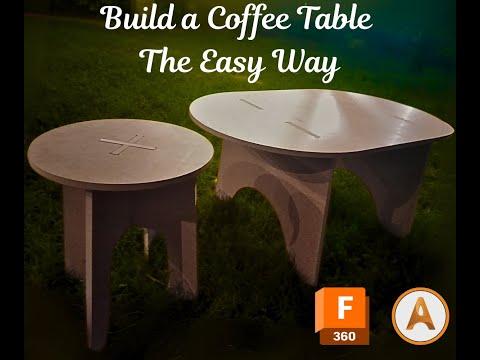

Have you ever wanted to create a unique piece of custom furniture for your living room? This project will guide you through making your very first coffee table—from designing a precise CAD model in Fusion 360 to generating tool paths in ArtCAM and, finally, machining and assembling your masterpiece. Whether you’re a beginner or a seasoned maker, this Instructable covers every step in detail while emphasizing design creativity, proper tool usage, and assembly tips. Get ready to combine modern digital fabrication with hands-on craftsmanship!
Here is a video that goes through all the processes in rapid way.
All thanks to Abo elnaga my friend because we made the coffee table and the stool, here is a link for his build HERE
Supplies

Software
- Fusion 360: This is used to create the CAD model and define all design parameters.
- ArtCAM: To import your design (saved as DXF) and generate accurate tool paths.
Materials
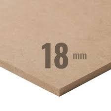
- MDF Sheet (18mm thick): The table top and legs.
- Wood (Optional): If you wish to add accent pieces or reinforcements.
- Adhesives: Wood glue (for assembly, if needed).
Tools & Machines
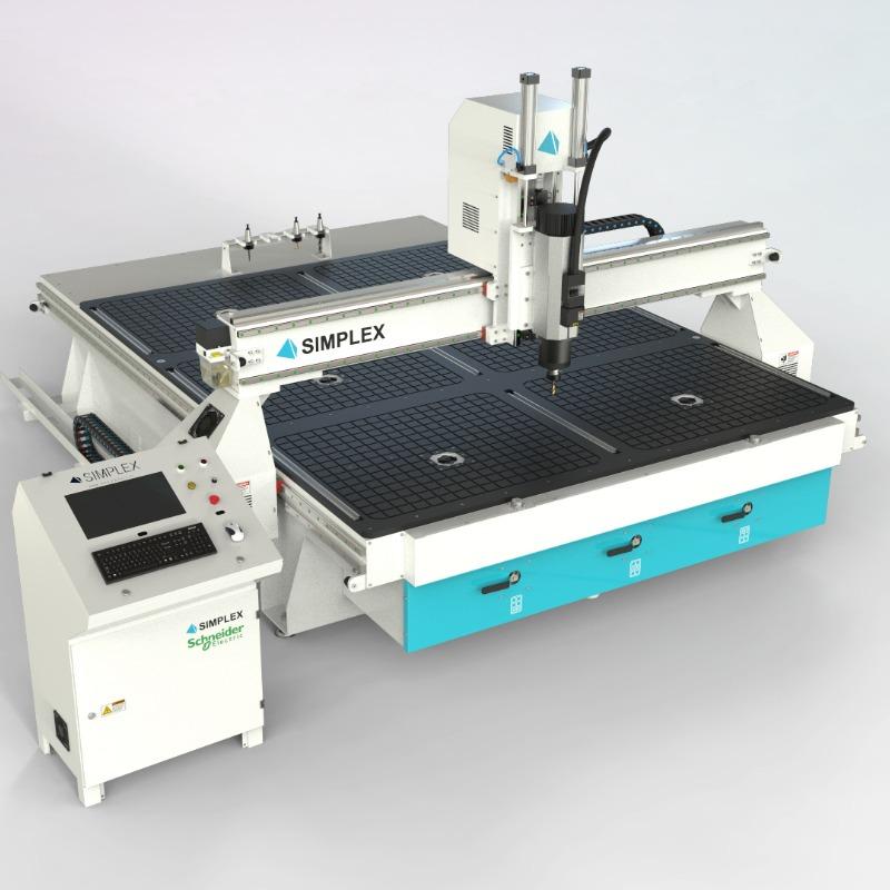
- CNC Router/Milling Machine: To cut your design with precision.
- Router Machine: For machining details or if doing manual work.
- Clamps: These are used for holding pieces in place during assembly.
- Sandpaper & Finishing Supplies: To smooth edges and finish the table.
Downloads
Designing Your Coffee Table in Fusion 360
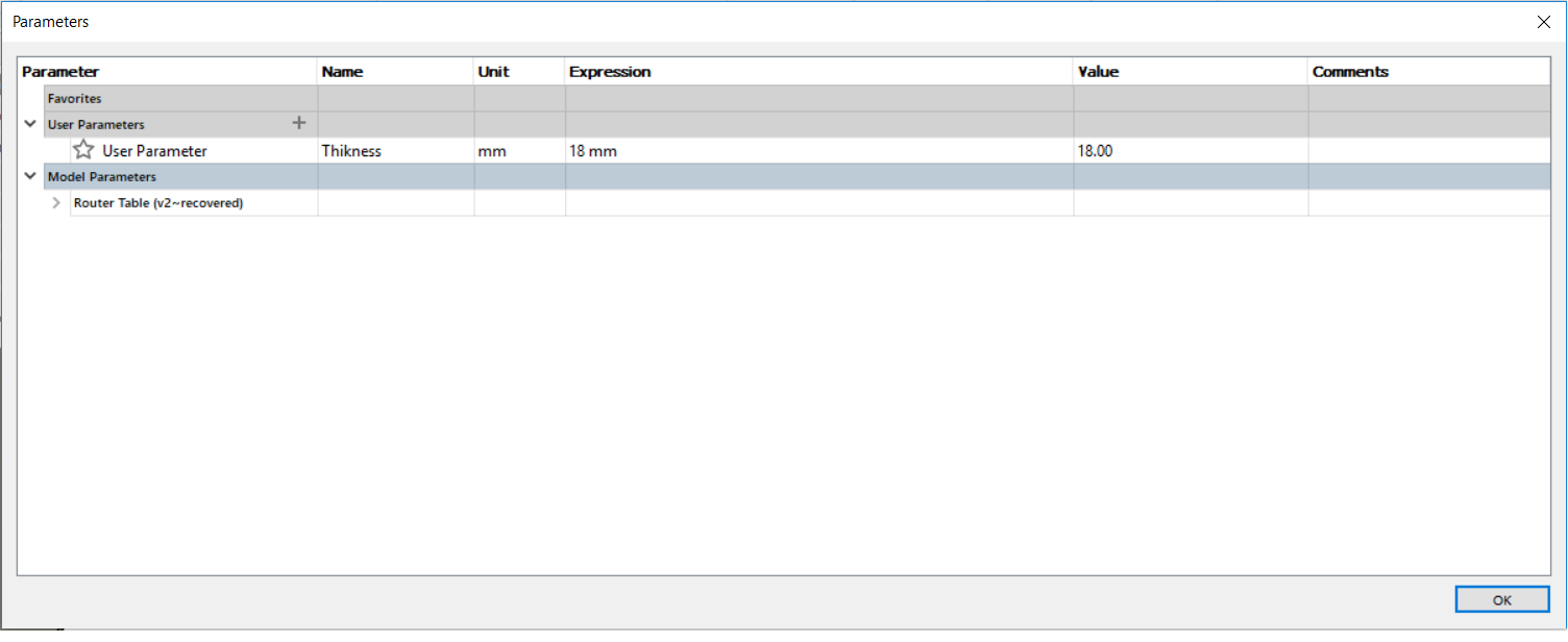
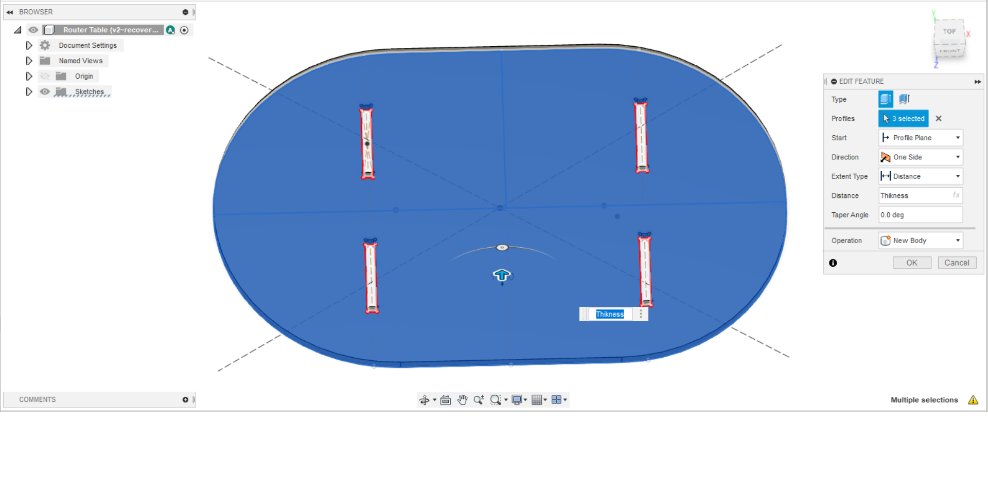


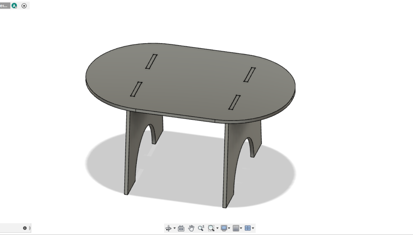
1.1 Concept & Sketching
- Brainstorm Your Design: Decide on the table’s shape and style. Consider incorporating modern curves or classic straight lines.
- Initial Sketches: Draft rough sketches on paper or digitally to finalize your design idea.
1.2 Creating the CAD Model
- Open Fusion 360: Start a new project and set up your workspace.
- Sketch the Table Top:
- Draw the outline of your table top. Use parametric dimensions so you can adjust the design easily later.
- Create features like rounded corners or unique cutouts as desired.
- Extrude & Add Details:
- Extrude the sketch to the thickness of your MDF sheet (18mm).
- Sketch and extrude the legs, either as integrated parts or separate components.
- Use the “Join” command to combine shapes if your design calls for it.
- Save & Export:
- Verify all dimensions and features.
- Export your design as a DXF file for further processing in ArtCAM.
Tip: Keep your design parametric so adjustments (such as overall dimensions or leg positions) can be easily made using Fusion 360’s “Change Parameters” feature.
Note: The table dimensions were 90*70*70 C
I will link the files down
Preparing the Design in ArtCAM
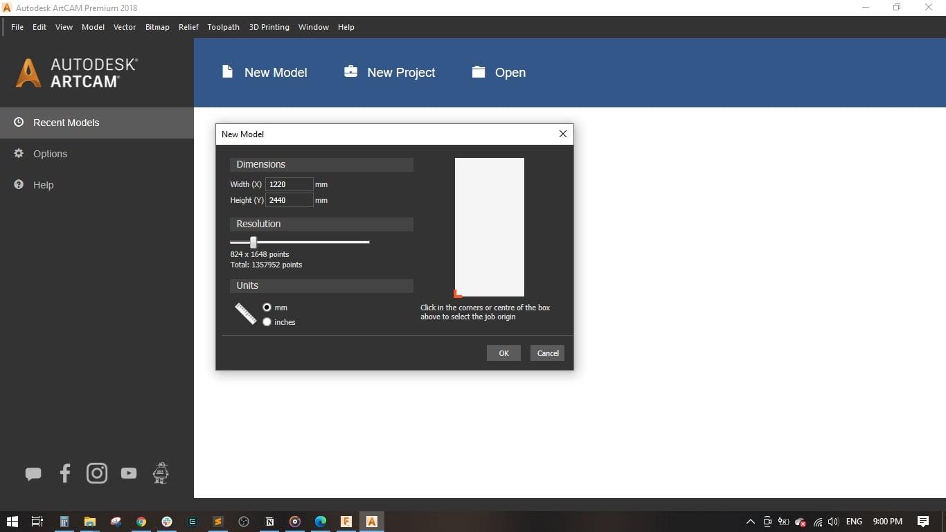
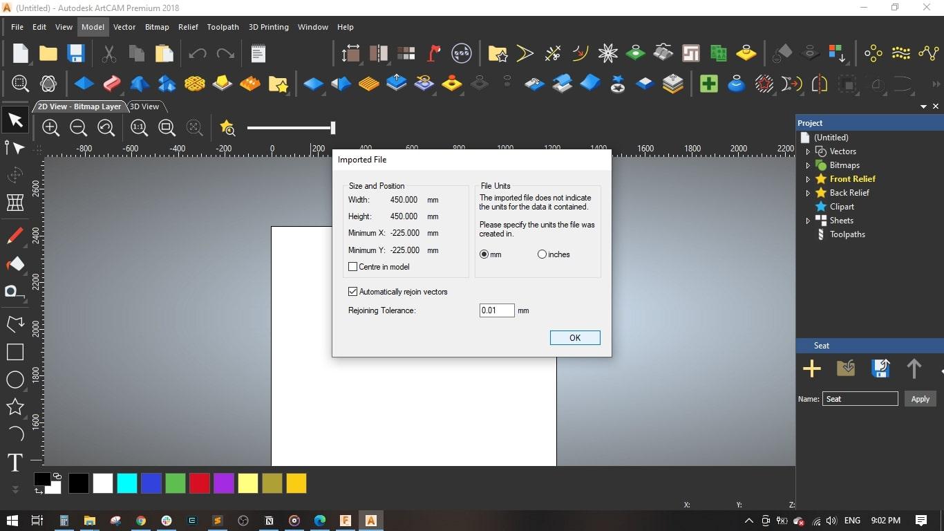
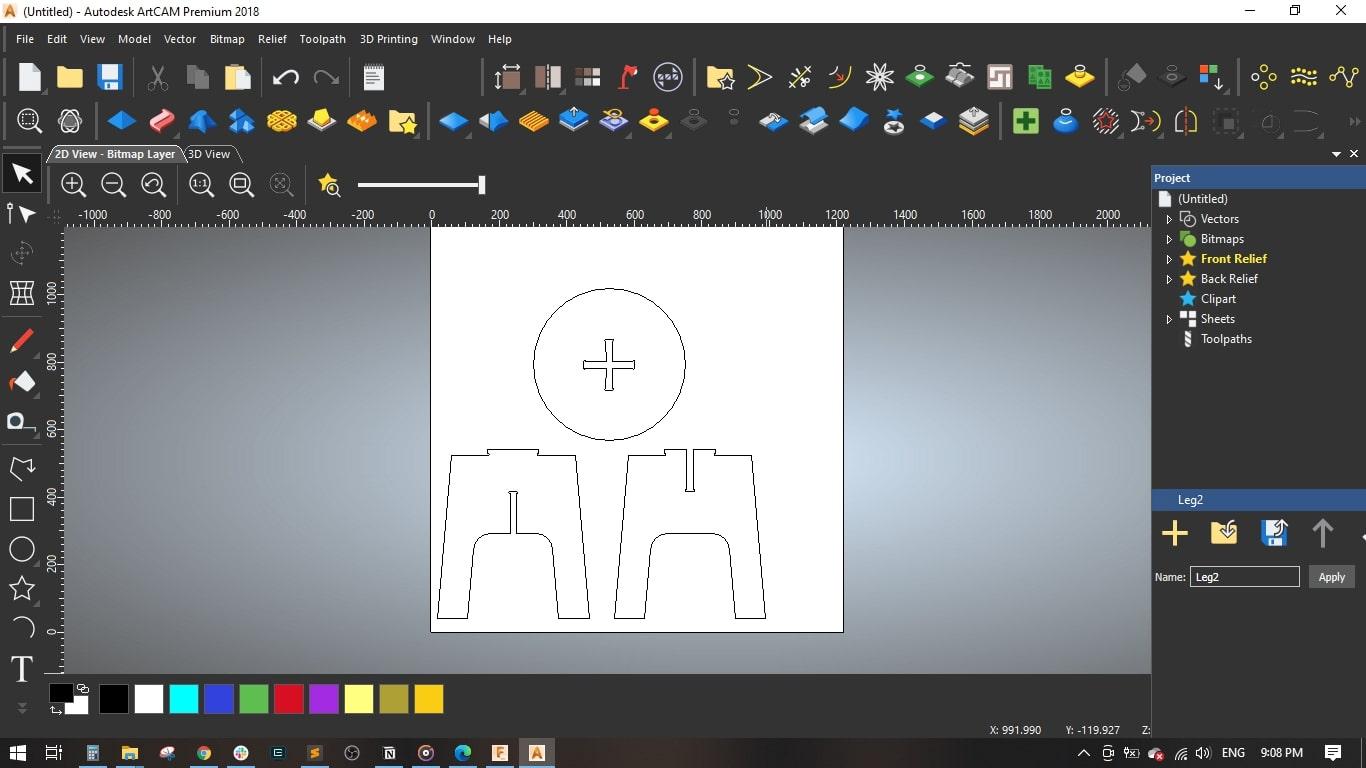
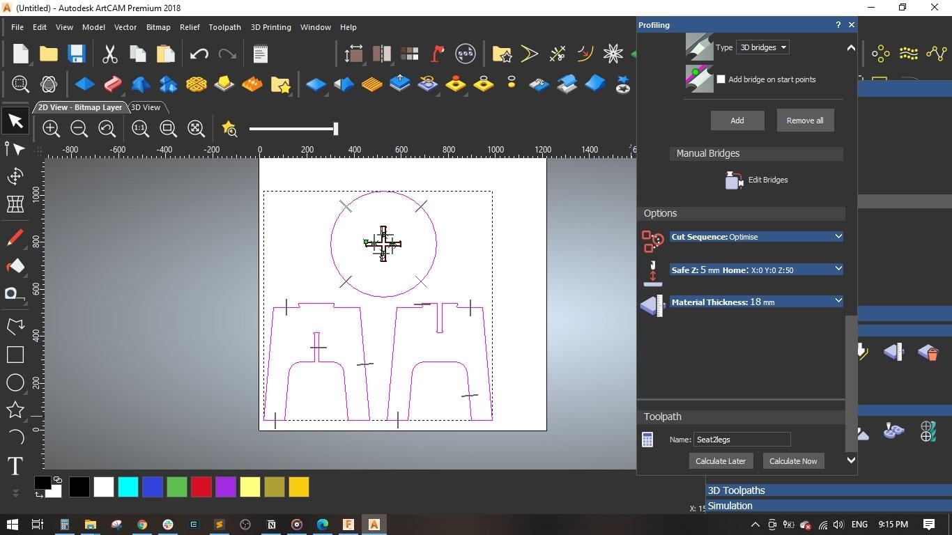

2.1 Importing Your DXF File
- Open ArtCAM: I opened ARTCAM and created a new model.
- I will be using an 18 mm MDF sheet with its standard dimensions of 122 cm * 244 cm
- Set the units to mm and the job origin to the left bottom corner.
- Then, I started importing the DXF files by dragging and dropping them into the work area.
- Setting Up the File:
- Verify the scale and alignment.
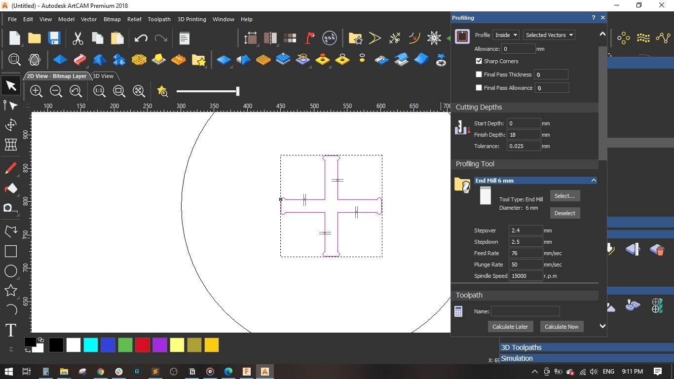
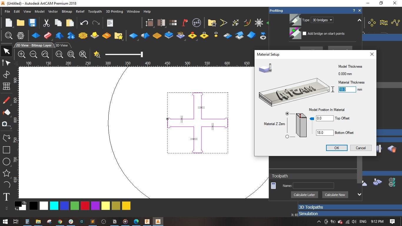
- I selected the cross-shape in the seat, selected Inside Profile, and set the finish depth to 18 mm.
2.2 Generating the Tool Paths
- Define Cutting Parameters:
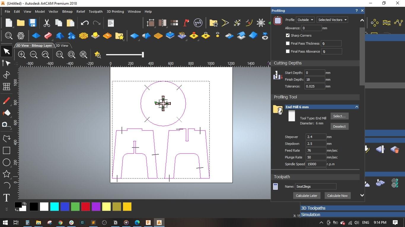
- I selected a 6 mm End Mill and set the cutting parameters as follows,
- Stepover = 2.4 mm
- Stepdown = 2.5 mm
- Feed Rate = 76 mm/sec
- Plunge Rate = 50 mm/sec
- Spindle Speed = 15000 rpm
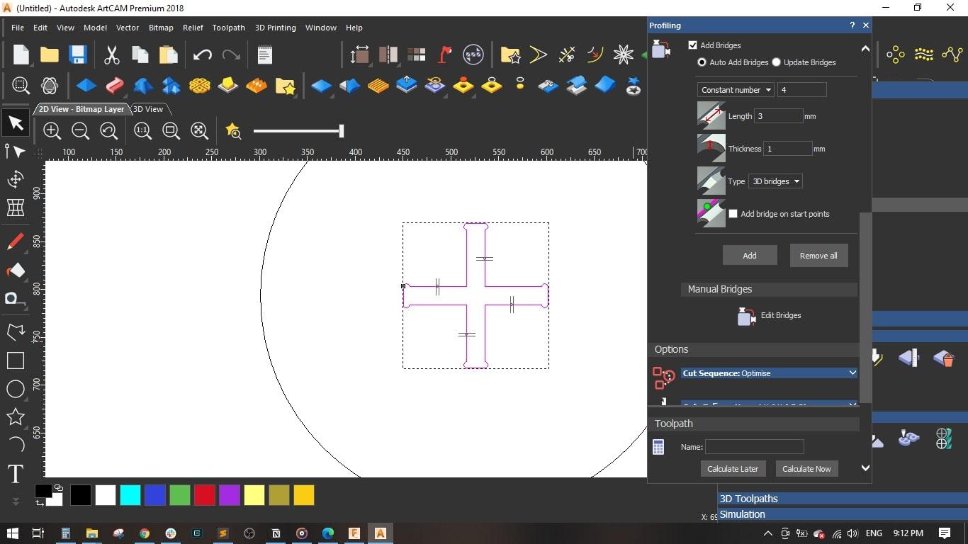
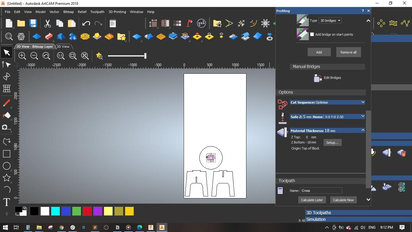
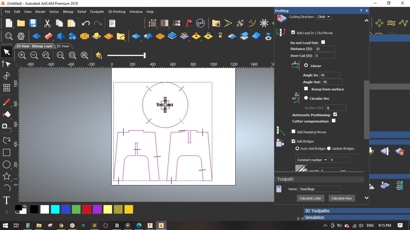
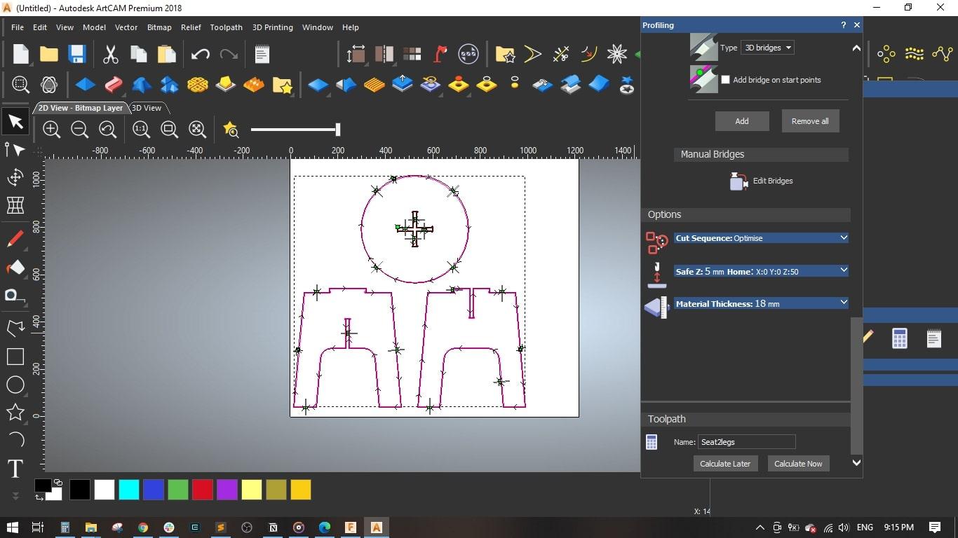
- I added bridges so as to fix the cut part with the board with tinny tabs.
- Material setup: Thickness = 18 mm and the material Z zero to the top.
- Named the toolpath with Cross and pressed Calculate Now
- Simulation & Verification:
- I selected the legs and seat without the cross-shape and selected Outside Profile
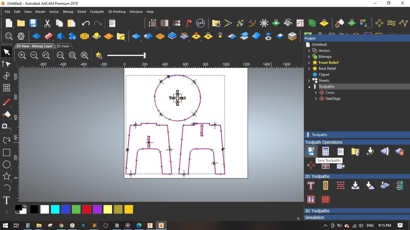
- Set the same parameters as the previous toolpath, named it Seat2legs, and pressed Calculate Now
- Finally, I saved the toolpaths. I selected Mach2 mm(*.cnc) as the machine file format.
- Export G-Code:
- Once the simulation is satisfactory, export the G-code for your CNC router.
Tip: Label your tool paths clearly (e.g., “Table Top Outer Cut,” “Leg Engrave”) to simplify setup on the machine.
Machining Your Coffee Table

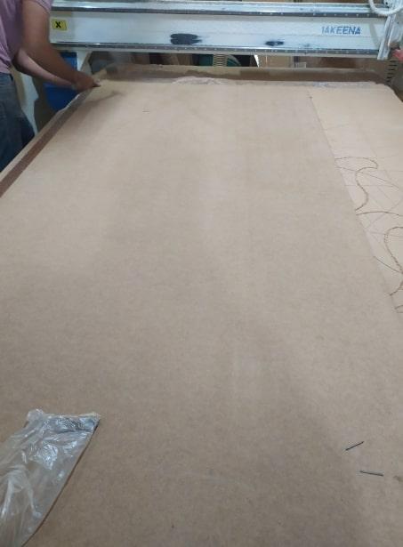
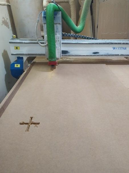
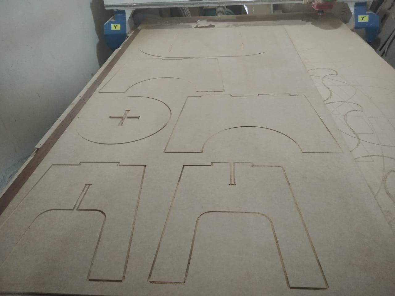

3.1 Setting Up Your CNC Machine
- Material Preparation:
- Secure your 18mm MDF sheet on the CNC bed with clamps or a vacuum table.
- Set the machine’s origin point (zero) according to your design reference.
- Load the G-Code:
- Transfer the G-code from ArtCAM to your CNC router’s controller.
- Test Run:
- Run a test on a scrap piece of MDF to confirm proper settings and tool paths.
3.2 Cutting Process
- Execute the Cuts:
- Start with the outer profile, then proceed to the detailed engravings or inner cuts.
- Monitor the machine for any adjustments or issues.
- Quality Check:
- Once the machine has finished, inspect all cut parts.
- Trim any rough edges and perform any necessary sanding.
Tip: Always follow safety guidelines while operating CNC machines. Wear appropriate personal protective equipment (PPE) and ensure the work area is clear of obstructions.
Assembly & Finishing

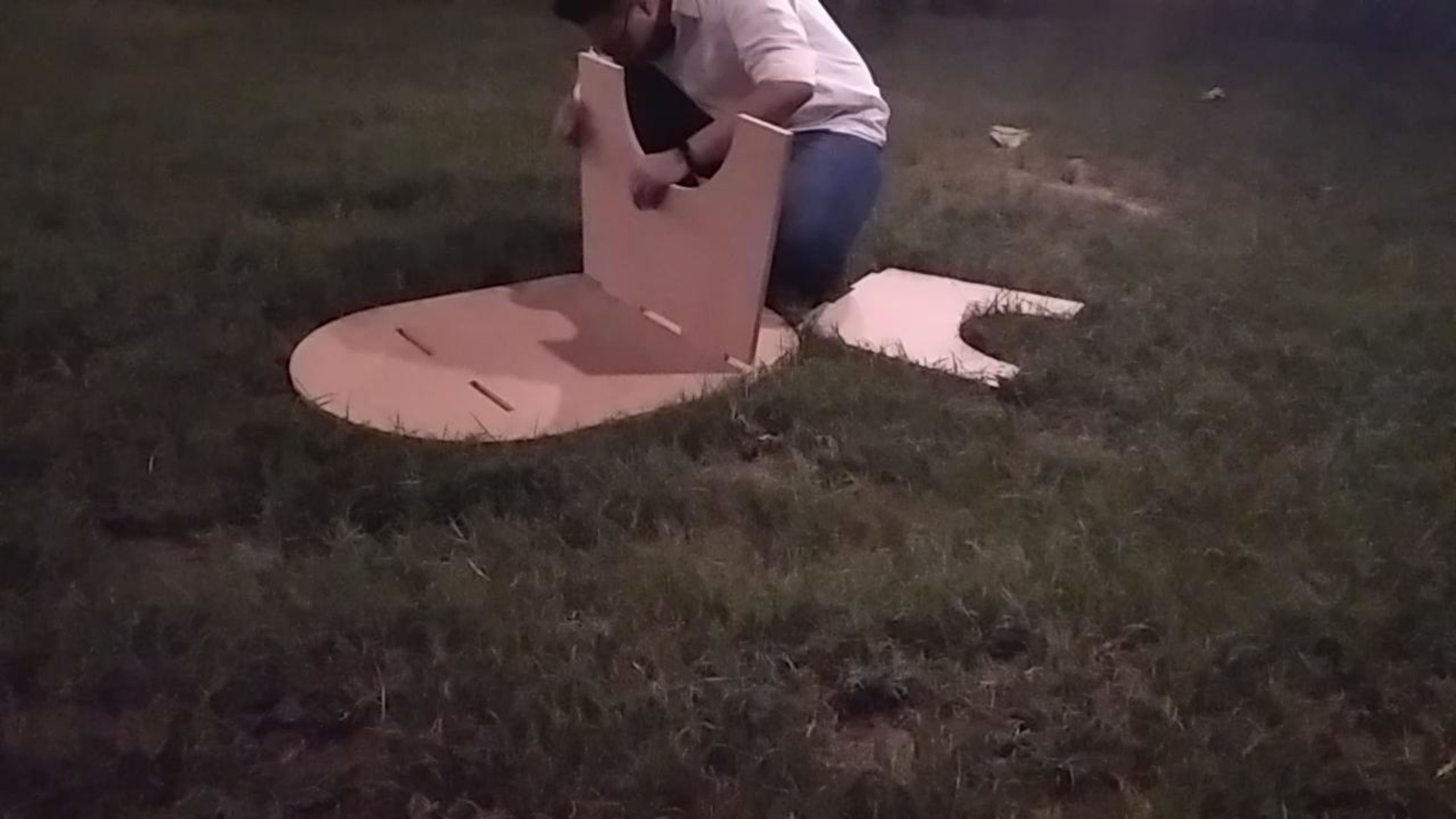


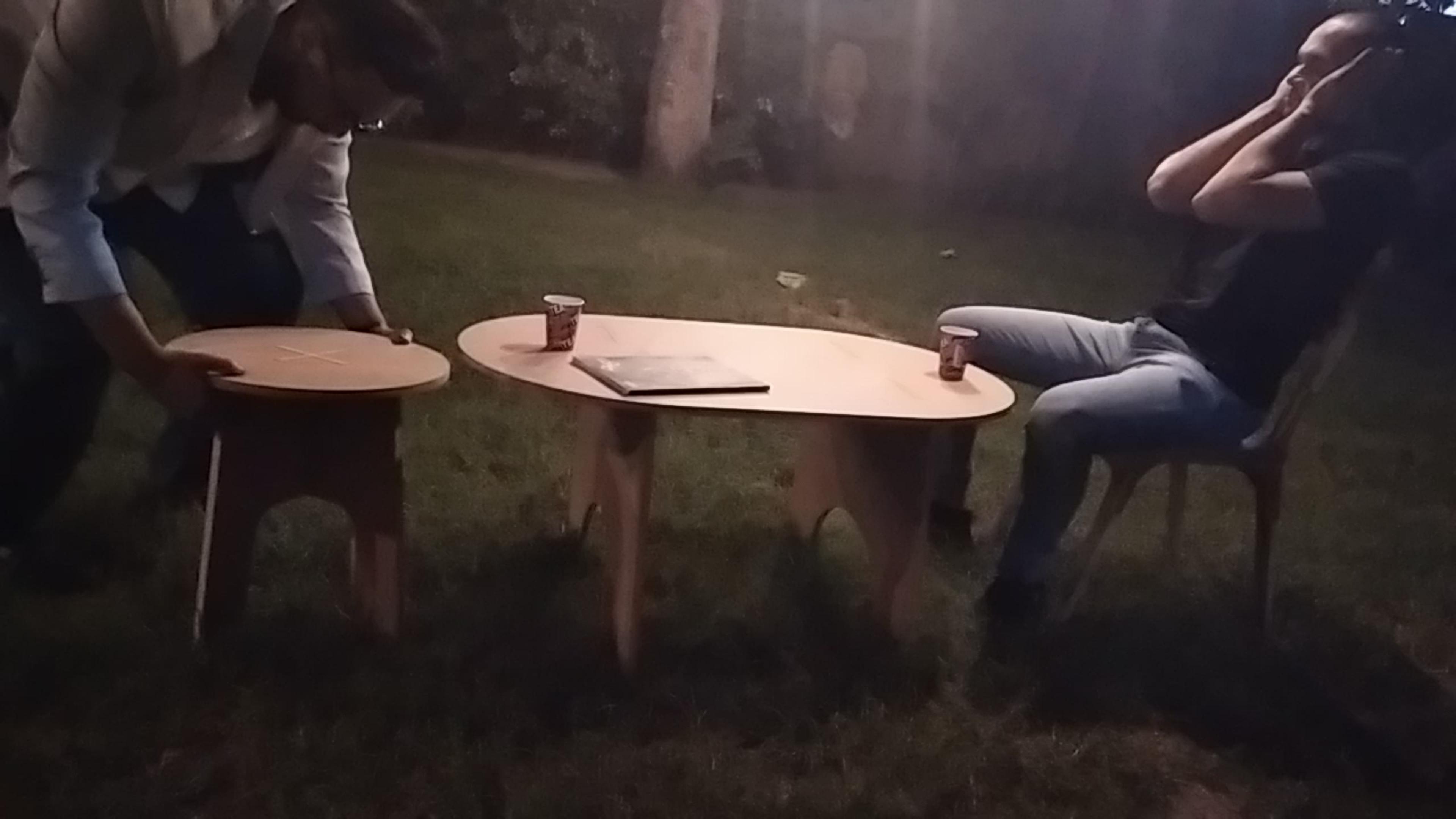
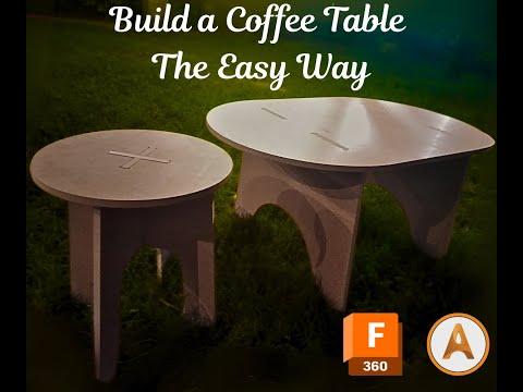
4.1 Assembly
- Dry Fit:
- Lay out all cut parts and dry fit them together. Check for alignment and fit.
- Final Assembly:
- If your design uses adhesives, apply wood glue at joints and clamp the pieces until dry.
- Alternatively, if you’ve designed interlocking parts, assemble them by hand for a clean, fast-fit solution.
4.2 Finishing Touches
- Sanding & Smoothing:
- Use sandpaper (start with 80 grit, then 120 and 220 for fine sanding) to smooth all surfaces and edges.
- Optional Finishes:
- Apply a wood sealant or paint for both aesthetics and durability.
- Consider adding additional design elements (like inlays or engraved patterns) using Fusion 360 and ArtCAM if desired.