The Electric Pentachrome: a 5-tone Touchless Musical Interface
by learningninja496i in Circuits > Microcontrollers
70 Views, 0 Favorites, 0 Comments
The Electric Pentachrome: a 5-tone Touchless Musical Interface
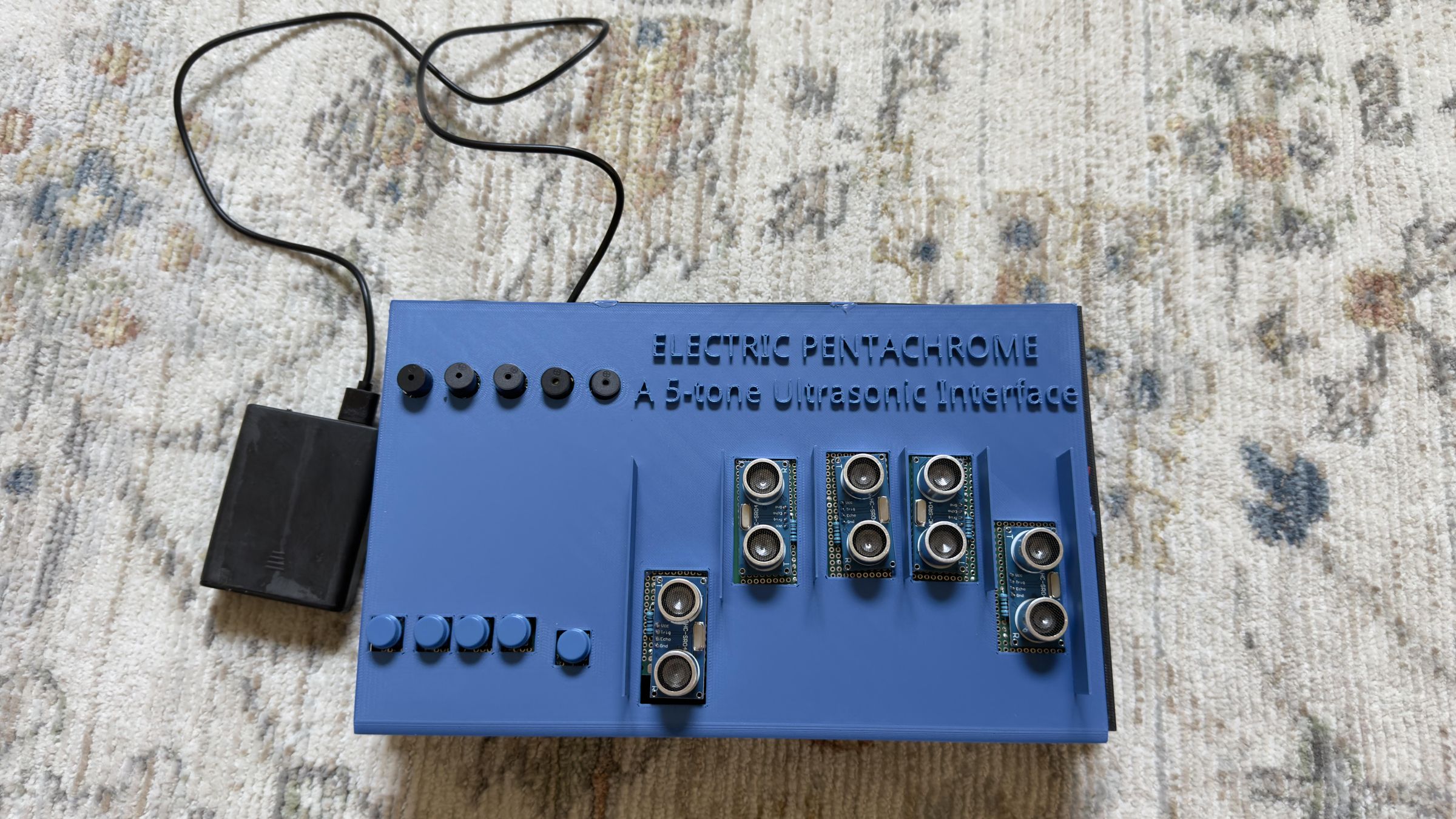
Since I was five, I have loved playing my favorite songs on the piano. However, one aspect of it I didn't like while playing was how widespread the instrument was, extending 5 feet wide. This made it difficult for me to play, as I could not stretch across it to play the different notes, and I was inspired to create an instrument that had a shorter range of notes, yet more notes to play.
The Electric Pentachrome, my custom-designed instrument, runs on a 5-volt power supply and utilizes 5 ultrasonic distance sensors, 5 buttons, 5 passive buzzers, and a Raspberry Pi Pico. The ultrasonic sensors determine the pitch of the note played, from 27 hertz (A0) to 7902 hertz (B8), encompassing 99 notes. The buttons determine whether the note is played or not. Each note on the distance sensors' "invisible fretboard" has approximately 1 centimeter of space, and the total height of it is 1 meter.
Supplies
Tools:
- Soldering Rod
- Device (needs to have Thonny IDE installed)
- Solder
- Multimeter
- 6 Small Breadboards (for prototyping)
- Electrical Tape
- Hot Glue Gun
Materials:
- 1x Raspberry Pi Pico - System Brain
- 1x Large Breadboard - Mounting for System Brain
- 5x 7cm x 3cm PCB - Component Mounting for Ultrasonic Sensors
- 2x 7cm x 9cm PCB - Component Mounting for Buttons and Buzzers
- 2x 8cm x 2cm PCB - Component Mounting for Buttons and Buzzers
- 5x Tactile Push Button - Trigger for Note Generation
- 5x Passive Buzzer - Variable Note Generation
- 5x S8050 Transistor - Current Regulation for 5V Rail
- 10x 1K Resistor - Current Limiter
- 5x 2K Resistor - Voltage Divider for Echo Pins
- 5x 10K Resistor - Button Voltage Regulation
- 5x HC-SR04 Distance Sensor - Distance Detection for Pitch Mapping
- 1x Power Bank - Power Supply
- Jumper Wires - Electrical Connection
Wiring
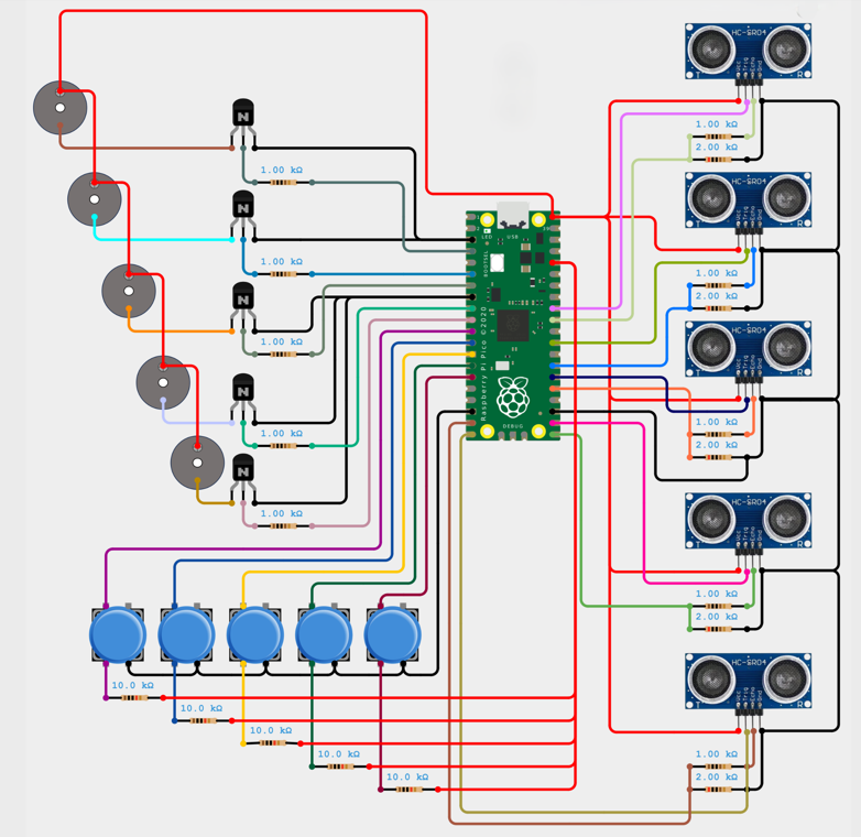
Wire the circuit shown above on breadboards. Note your GPIO pins can vary; these are just what I used in my circuit.
Coding
Write the following code in Thonny IDE. Note that you will have to adjust the pin numbers in the code if you change your GPIO pins.
How the Code Works
First, the compiler imports the necessary modules and defines the note frequencies and the GPIO pins:
Next, it defines the functions for playing notes, stopping notes, and gathering distance values:
Then, it ends with the main loop of gathering distance, checking if the button is pressed or not, and playing (or not playing) the corresponding notes:
CAD Design
From this instructable, download the files titled "Electric Pentachrome Lid" and "Electric Pentachrome Box" which are the lid and box for the instrument, respectively. Then 3D print them.
The Electric Pentachrome lid looks like this:
Soldering
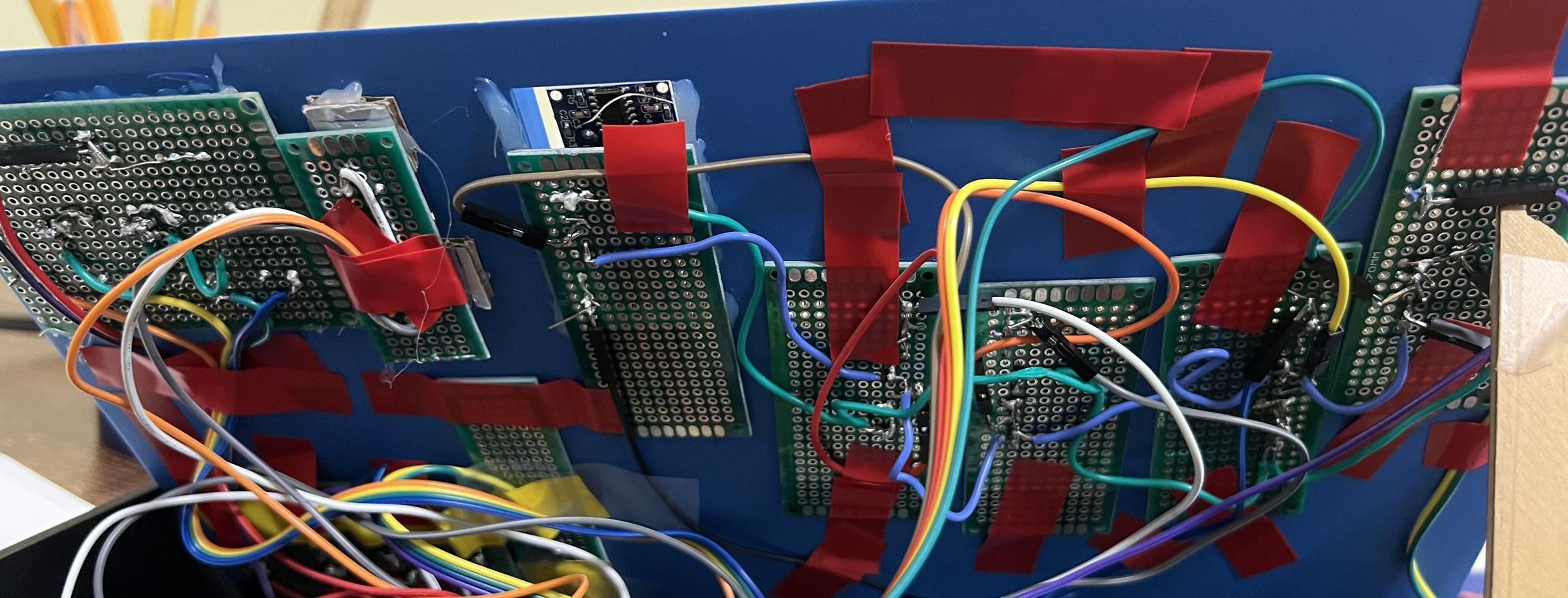
Solder the components in the following format:
- 7cm x 9cm PCB: 4 buttons
- 7cm x 9cm PCB: 4 buzzers
- 8cm x 2cm PCB: 1 button
- 8cm x 2cm PCB: 1 buzzer
- 5 7cm x 3cm PCBs: Ultrasonic sensors
With the exception of the passive buzzers and the buttons (more information in the next step), solder the entire circuit for each component on the PCB itself. For the passive buzzers and the buttons, just solder them onto the PCB.
Breadboard Circuit
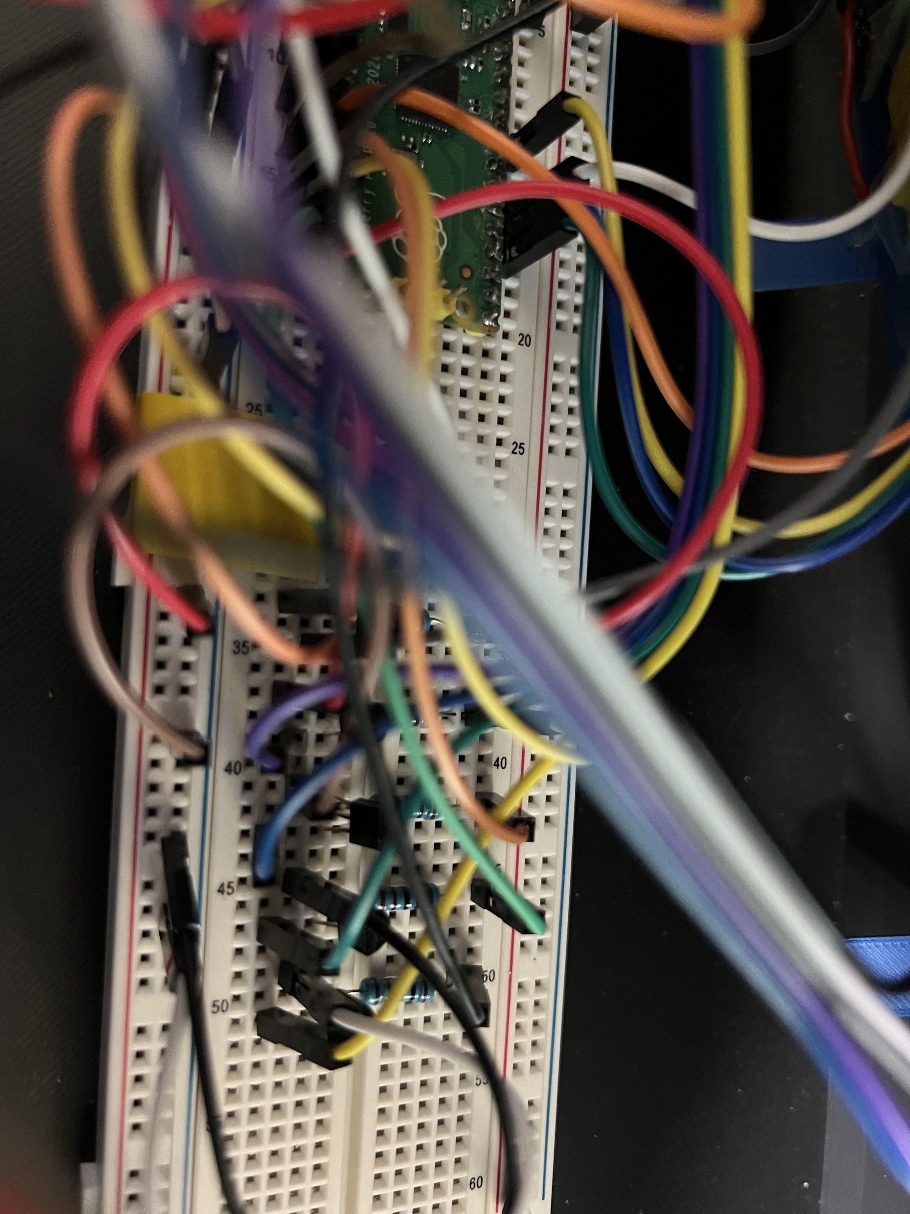
Next, mount the Pico on the breadboard, and connect the corresponding pins in the circuit to the Pico. The only other things on the breadboard are the transistor-resistor setup for the passive buzzers, and the resistors leading to GND for the buttons.
Box Assembly
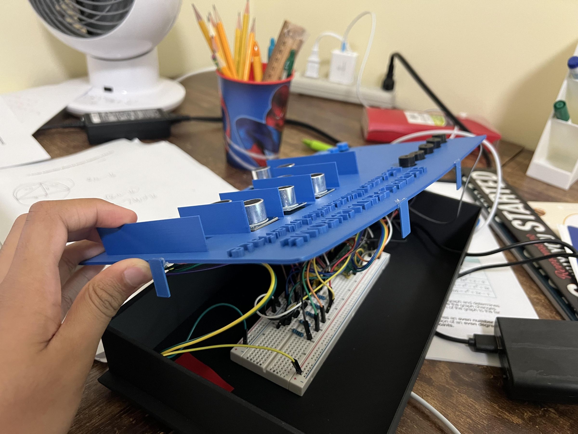
In the 3D-printed design, there are 4 rectangular pieces. Glue them to the sides of the box, as shown. These make sure the box lid does not slide off of the box.
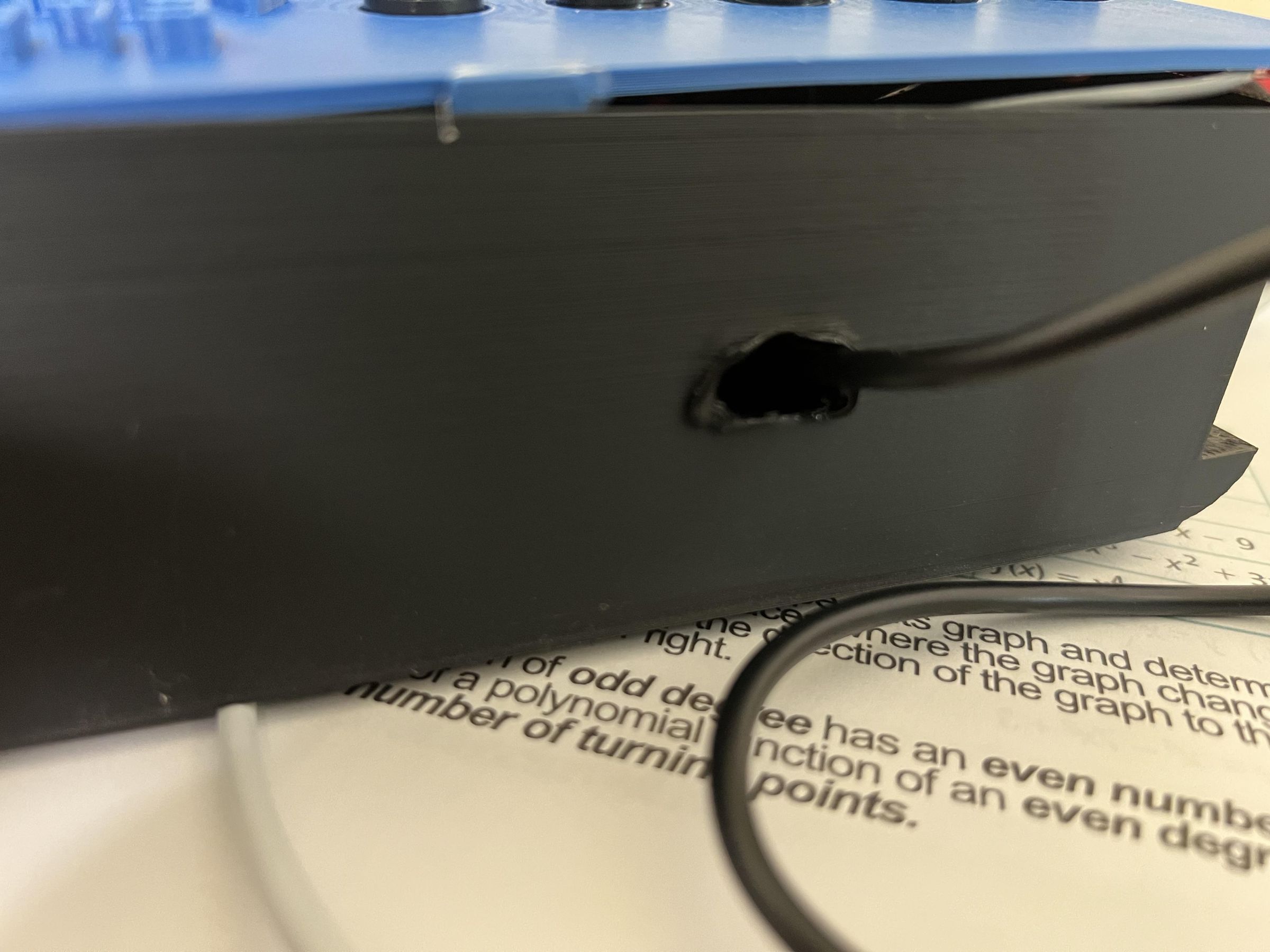
Next, use your soldering rod to burn a small hole in the box. 3D printing plastics like PLA melt around 60 degrees Celsius, and the soldering rod is at a temperature of 350-400 degrees Celsius. The hole is so the USB that runs from the Pico can connect to a power bank.
Final Circuit Integration
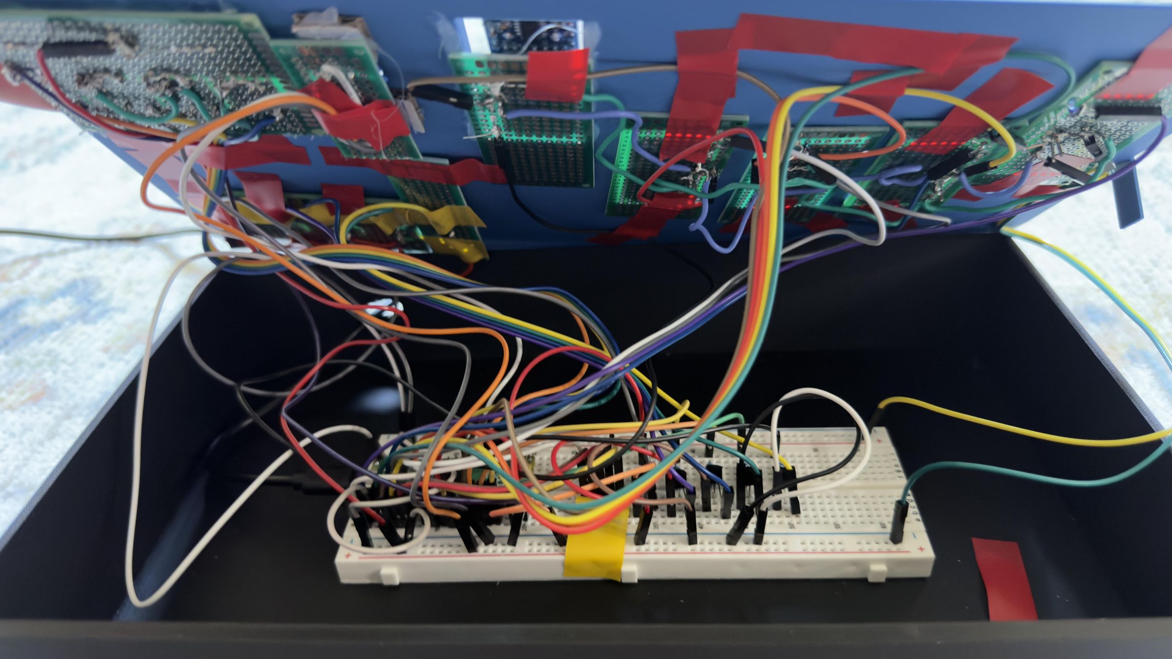
Finally, use electrical tape to stick the PCBs to the lid of the holes in the lid and to stick the breadboard to the bottom of the box to ensure it does not move.
Slide the USB wire through the hole, and connect it to the Pico and the power bank.