The Optimal Window for Optimal Window Optimisation — an ESP32 That Tells You When to Open the Windows
by mattmk1 in Circuits > Electronics
967 Views, 11 Favorites, 0 Comments
The Optimal Window for Optimal Window Optimisation — an ESP32 That Tells You When to Open the Windows
.jpg)
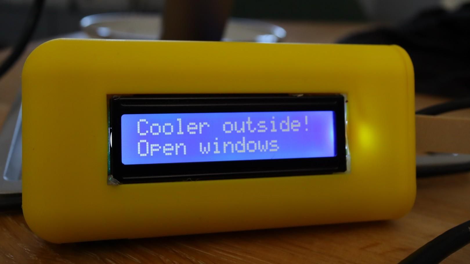
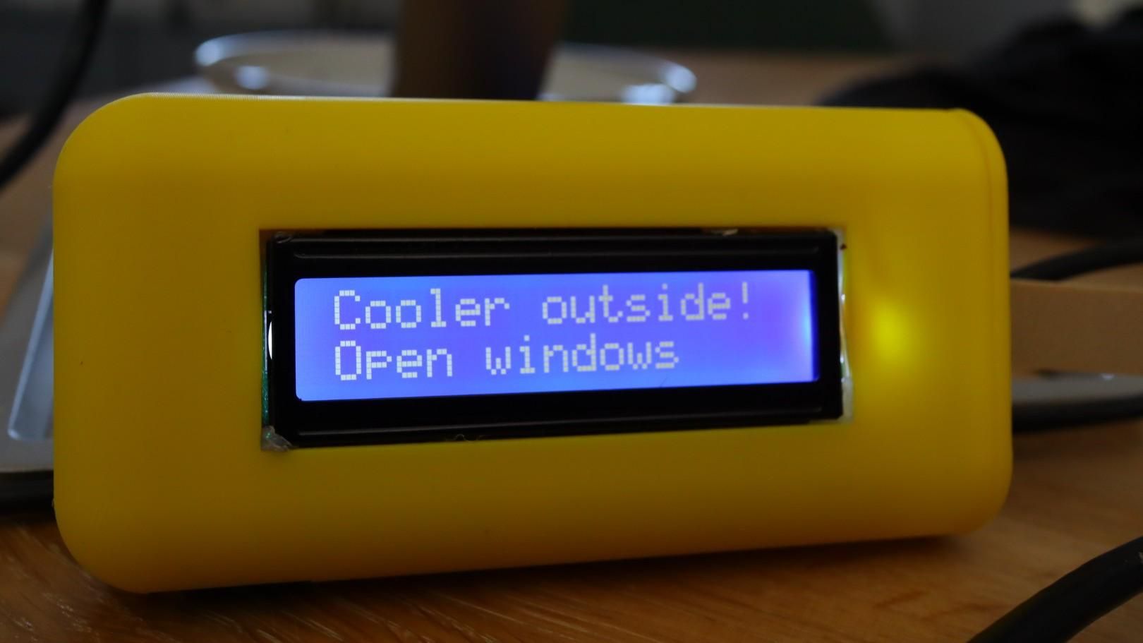
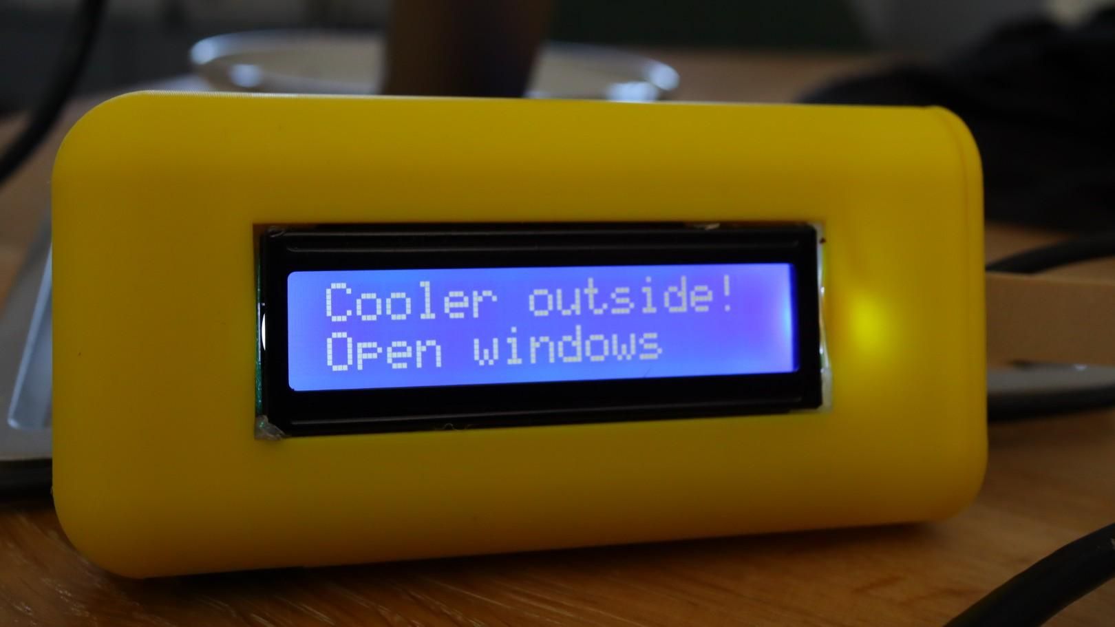
It is peak heatwave. You find yourself outside, arms out like a meerkat, trying to sense the weather with your bare skin like some sort of Bronze Age farmer. It doesn't work, obviously. Realistically, you're standing there checking your phone, or asking an AI, whether now is the moment to pry open every window in the house — and that works fine, right up until you forget to do it.
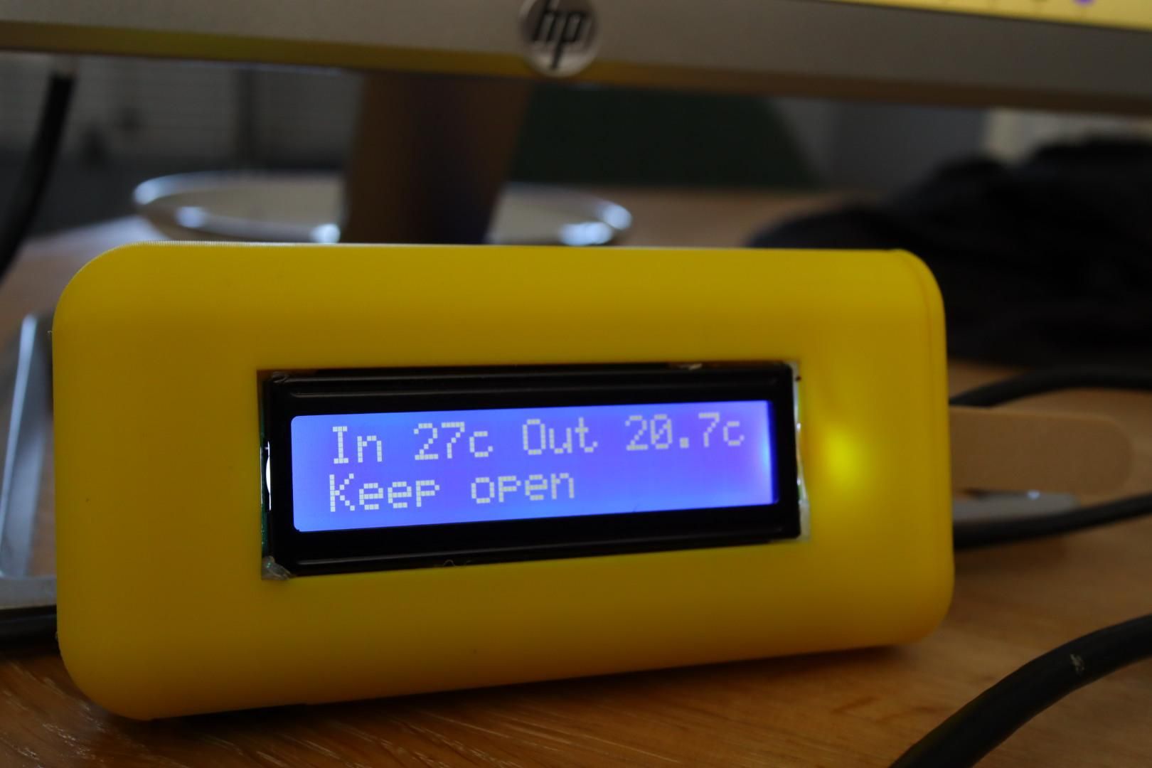
Because that's the actual problem. Not knowing when — an app can tell you that. The problem is remembering to ask. So why not let the house tell you instead? A small ESP32, a temperature sensor, and — because this is a device that deserves proper ceremony — a 90s-modem bleep-bloop of a notification the exact moment the outside air turns properly, meaningfully cooler than the air in your living room.
Then it shuts up until the reverse happens — when the temperature outside creeps back past the temperature inside, it plays a different tone, letting you know it's time to shut the house up before you trap tomorrow's heat in overnight. And because nobody wants to hear a dial-up handshake tone at 3am, it stays silent from 9pm to 7am regardless of what the thermometer's doing.
Build Notes
- Enclosure was initially very square, but a quick fix by expanding the radius within Fusion without needing to redesign the entire enclosure
- Don't glue the base on until the USB is threaded through, the gap allows the USB cable to be added, the stick keep it in place (and hides the wire!)
- Definitely solder instead of jumper wires if you can, it will fit in much better
Changes If I Built Again
Soldered wires - I would recommend a headerless ESP32 and solder the wires, you will find it much easier to fit together... I just rushed it because I wanted to see my first designed 3d print together, the enclosure is close to ice lolly size, but that meant the electronics were a bit tight
Temperature sensor - I didn't spot this initially but the sensor not the most accurate, shop for another compatible sensor or use what you have
Future enhancement - Consider an outdoor sensor instead of the API based approach
Supplies
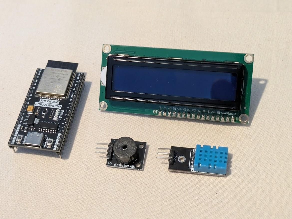
ESP32 Dev Board - I used a Freenove ESP32 I had lying around, but any will do
DHT11 Sensor - Heat and humidity sensor, you could swap this for something more accurate
HW-508 Passive Buzzer Module - For the bleep bloop noises, you could skip this if you don't have it
1602 LCD module - I went for the 12C serial model (because I had one from another abandoned project
Jumper Cables - I would recommend soldering here instead if you can as space is limited and it was difficult to fit
USB Cable - USB C for me, but match to your ESP32 (smallest USB C end you can find to fit through 3d printed end cap)
3D printer (Optional) - You could skip an enclosure or build your own
Glue gun
Fire Up the 3d Printer
No magic here, just grab the files and add them to your preferred 3D printer
This was my first attempt at using Fusion, I had always printed files I found online...
If you haven't used Fusion before don't panic the AI powered help side bar is really helpful, my first version was very boxy, but after a first print and review the second was much better, with a few tweaks to make things fit better
Electronics
Whilst the 3D printer is running grab your electronics and a laptop/pc
First step is to wire everything together
DHT11 VCC → ESP32 3V3
DHT11 GND → ESP32 GND
DHT11 DATA → ESP32 GPIO 4
LCD VCC → ESP32 5V
LCD GND → ESP32 GND
LCD SDA → ESP32 GPIO 21
LCD SCL → ESP32 GPIO 22
Buzzer + → ESP32 GPIO 18
Buzzer − → ESP32 GND
Add Code to Your Esp32
I have added code so you can just copy it over, but you will want to make a few changes to ensure the location is correct and your wifi connects
Installation instructions
You don't need the Arduino IDE or any command-line wrangling for this — Thonny does everything: flashing MicroPython onto the board, and copying your files across afterwards.
1. Install Thonny
Download it free from thonny.org — Windows, Mac, and Linux all supported. Install it and open it up.
2. Plug in the ESP32
Connect it to your computer with a USB cable that actually carries data (not a charge-only cable — if the board doesn't show up in the next step, this is the first thing to check).
3. Install MicroPython onto the board
- In Thonny, go to Tools → Options → Interpreter
- Set the interpreter dropdown to MicroPython (ESP32)
- Click Install or update MicroPython (esptool) at the bottom of that dialog
- Choose your board's port (it'll usually show up as something like COM3 on Windows, or /dev/cu.usbserial-XXXX on Mac)
- Pick the latest stable ESP32 firmware from the list and hit Install
- Wait for it to finish — you'll see progress in the log, and Thonny will tell you when it's done
4. Confirm the connection
Back in the main Thonny window, the Shell panel at the bottom should now show a MicroPython prompt (>>>). If it doesn't, use the Stop/Restart button (the red circle) in the toolbar to reset the board and reconnect.
5. Get the LCD driver onto the board
This project needs an I2C LCD driver library (lcd.py) sitting alongside your main script. Save it to your computer, then:
- File → Open, select lcd.py from your computer
- With it open in Thonny, go to File → Save As
- Choose MicroPython device (not "This computer") when prompted
- Save it as lcd.py — the filename matters, since that's what the script imports
6. Upload the main script
- Open window_advisor.py in Thonny the same way (File → Open, from your computer)
- Before saving, update the SSID and PASSWORD values at the top to match your own WiFi
- File → Save As → MicroPython device
- Save it as boot.py — this exact name matters, since it's what the ESP32 automatically runs on boot, without Thonny needing to be open at all
7. Test it
With main.py on the board, click the Stop/Restart button to reboot it. You should hear the two-note startup chime, then see "Connecting WiFi" appear on the LCD. Watch the Shell panel too — the script prints its readings there every minute, which is the easiest way to check it's behaving before you seal it into an enclosure.
8. Disconnect and power independently
Once it's working, you can unplug it from your computer and power it from any USB adapter — it'll run standalone from main.py every time it boots.
Troubleshooting
If you find that the device is not connecting try another USB cable, they can be quite sensitive to lower quality cables
Downloads
Test and Assemble
This is the part where I recommend taking your time, ideally a soldered version would work much better! I skipped this and forced the ESP32 into the case... I don't recommend the approach I used.
- Add the buzzer - I used hot glue to attach this at the top before the screen goes it, it is quite simple just glue and place
- Add the sensor - You may need to adjust the opening if you have used a different sensor
- Add the screen - Line up the screen and hot glue into place, this was a little fiddly since the sensor is in place, but the glue gives a bit of time for adjustment
- Add the ESP32 - Ensuring the screen glue has set push the esp32 in as far as you can, you'll need enough space for the end of the USB cable so that the end cap goes on
- Test - Before you commit completely test everything again
- Glue the stick - Ensuring the USB cable is through and then glue the stick in place from the inside
- Glue the end cap in place
Time for a celebratory ice cream!