The Pure Analog RGB Lamp: a Freeform Dead-Bug Masterpiece
by Kunnu_07 in Circuits > Electronics
106 Views, 1 Favorites, 0 Comments
The Pure Analog RGB Lamp: a Freeform Dead-Bug Masterpiece
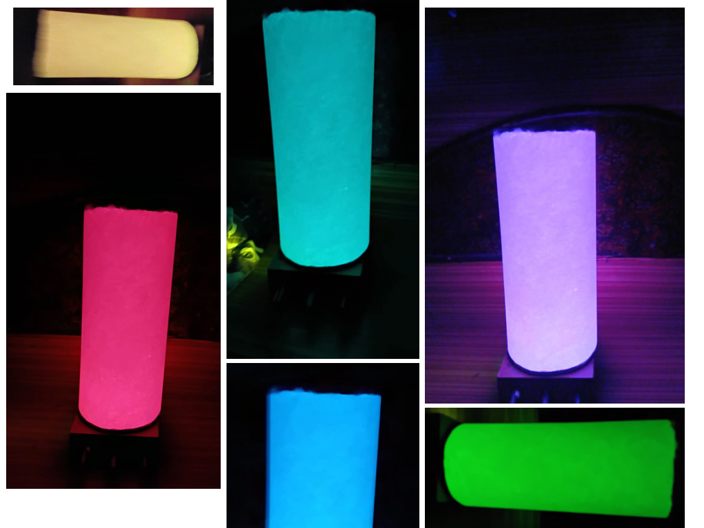
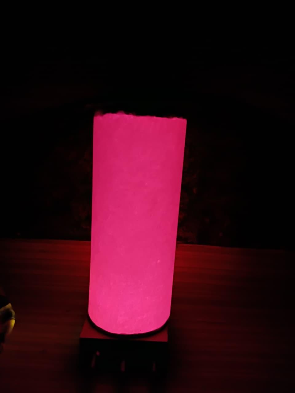
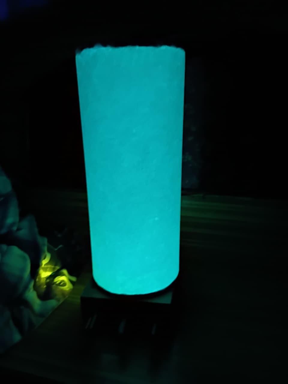
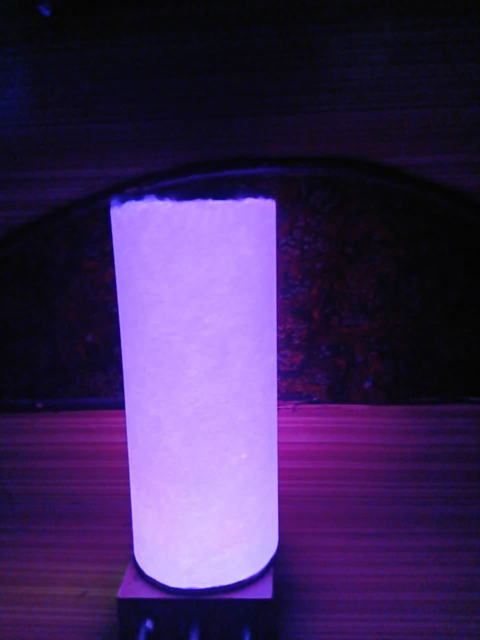
Most modern color-changing lamps rely on digital shortcuts—microcontrollers, code, and printed circuit boards (PCBs). This project rejects those conventions to celebrate the raw art of discrete electronics.
Built strictly without any circuit boards, this portable lamp utilizes a freeform "dead-bug" layout inside an upcycled cardboard chassis base. The component legs and insulated jumper wire paths connect directly in mid-air.
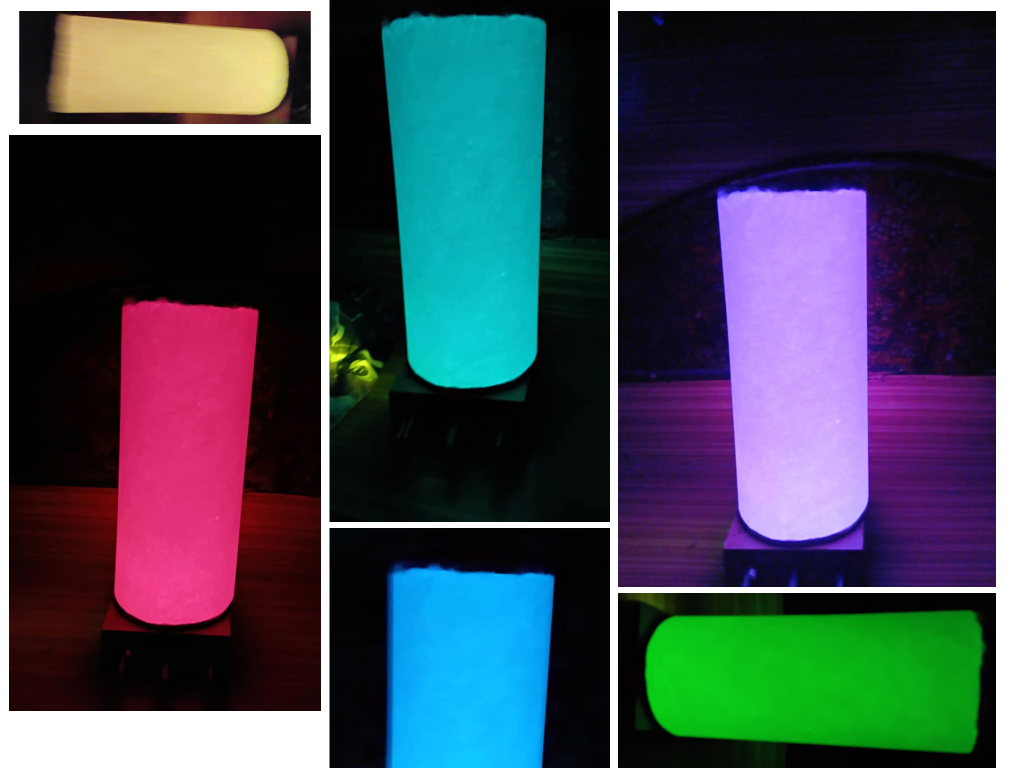
The exterior diffuser uses a single sheet of A4 printer paper rolled into a sleek cylinder. The subtle, organic wood-pulp fiber texture of the paper acts like artisan parchment when lit, creating a beautiful manual palette mixer.
Supplies
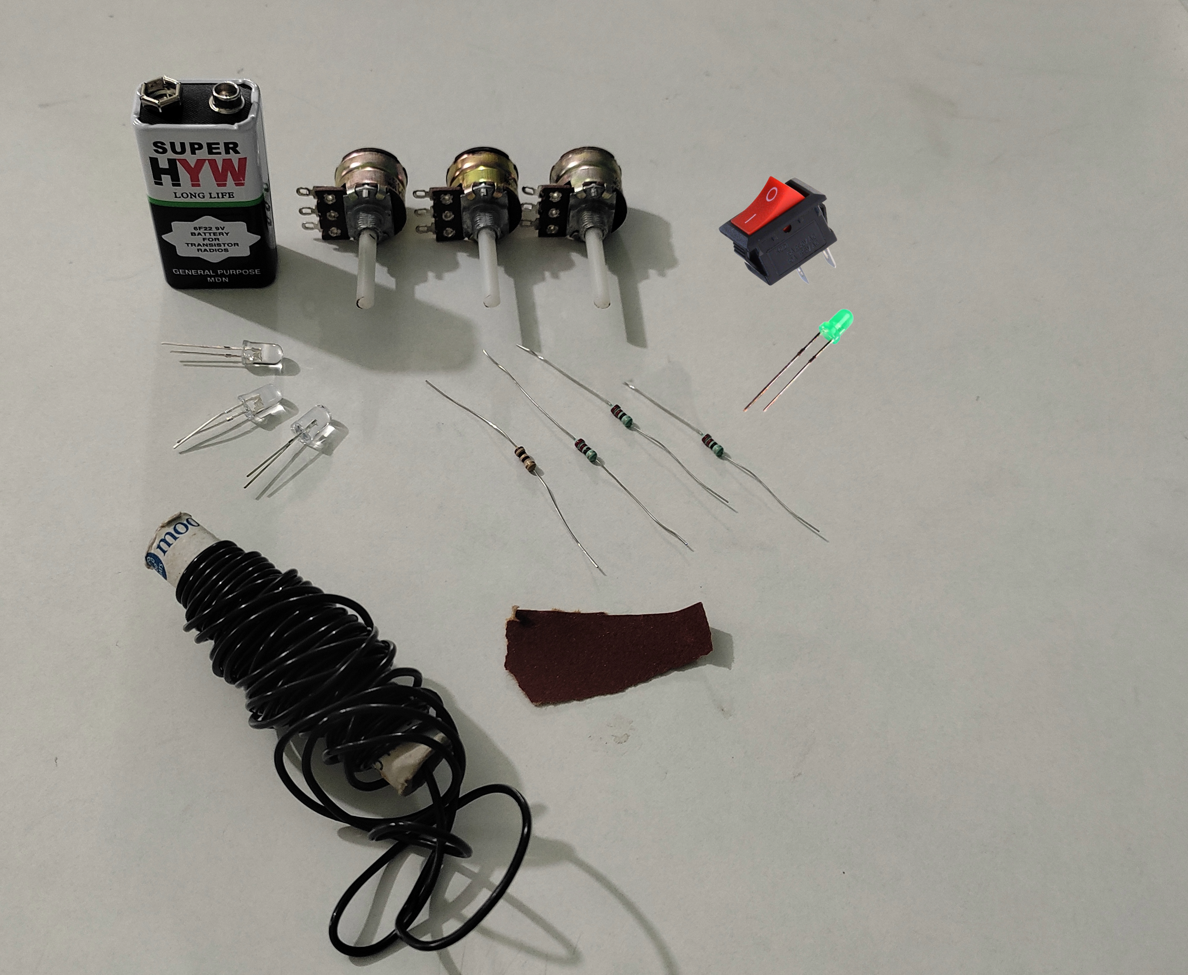
Controls: 3 × 10 kΩ Switched Potentiometers
LEDs: 1 × 5mm Red, 1 × 5mm Green, 1 × 5mm Blue, 1 × 5mm Green (Indicator)
Resistors: 1 × 100 Ω (Red line), 3 × 220 Ω (Green and Blue lines and indicator light)
Chassis & Shell: 2mm thick MDF board or ordinary cardboard (the thicker, the better), 1 × A4 White Printer Paper sheet (75 GSM).
Power & Switching: 1 × 9V Battery, 1 × Battery Clip, 1 × Red Rocker Toggle Switch
Tools: Soldering iron, wire cutters, scissors, craft knife, and fine sandpaper.
Building Materials: Insulation tape, clear cello tape, superglue or white glue, aluminium foil.
Dimensioning & Fabricating the Cardboard Chassis
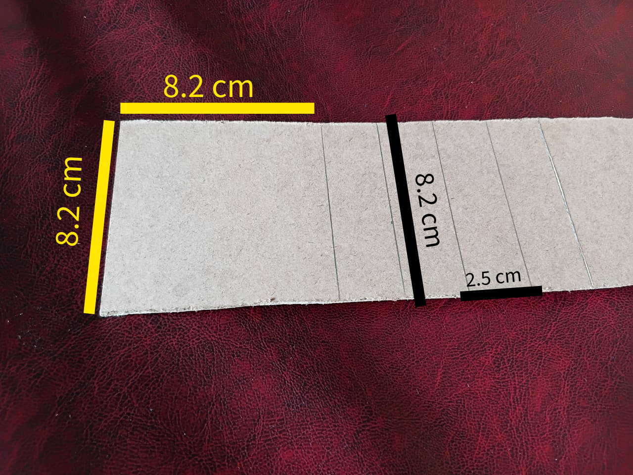
- Take a piece of MDF Board or ordinary Cardboard.
- Mark the length given in the image (or feel free to use your own custom dimensions).
- Cut the MDF Board or Cardboard in those lengths using a craft knife.
Placing the Pots
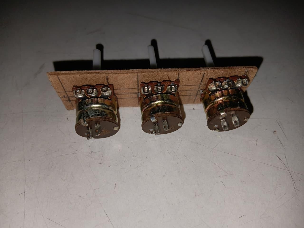
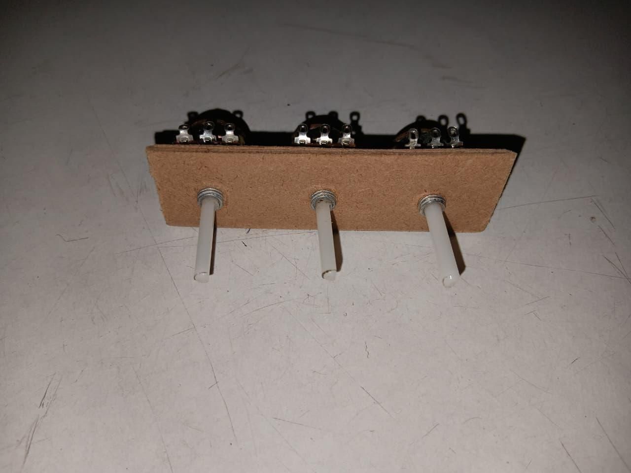
- Now take one of the side rectangles.
- Mark the points where you want the pots (potentiometers) to be placed.
- Punch a hole through the points, use a pair of scissors, or a drill bit to make the hole bigger.
- Place the pots in the holes.
- the pots have screw in themselves below the rotating knob, you can use them to automatically make the screw rings in the board or can use the hex nut that come with them to hold them tightly in the board, just as shown in the images.
Making the RGB Led
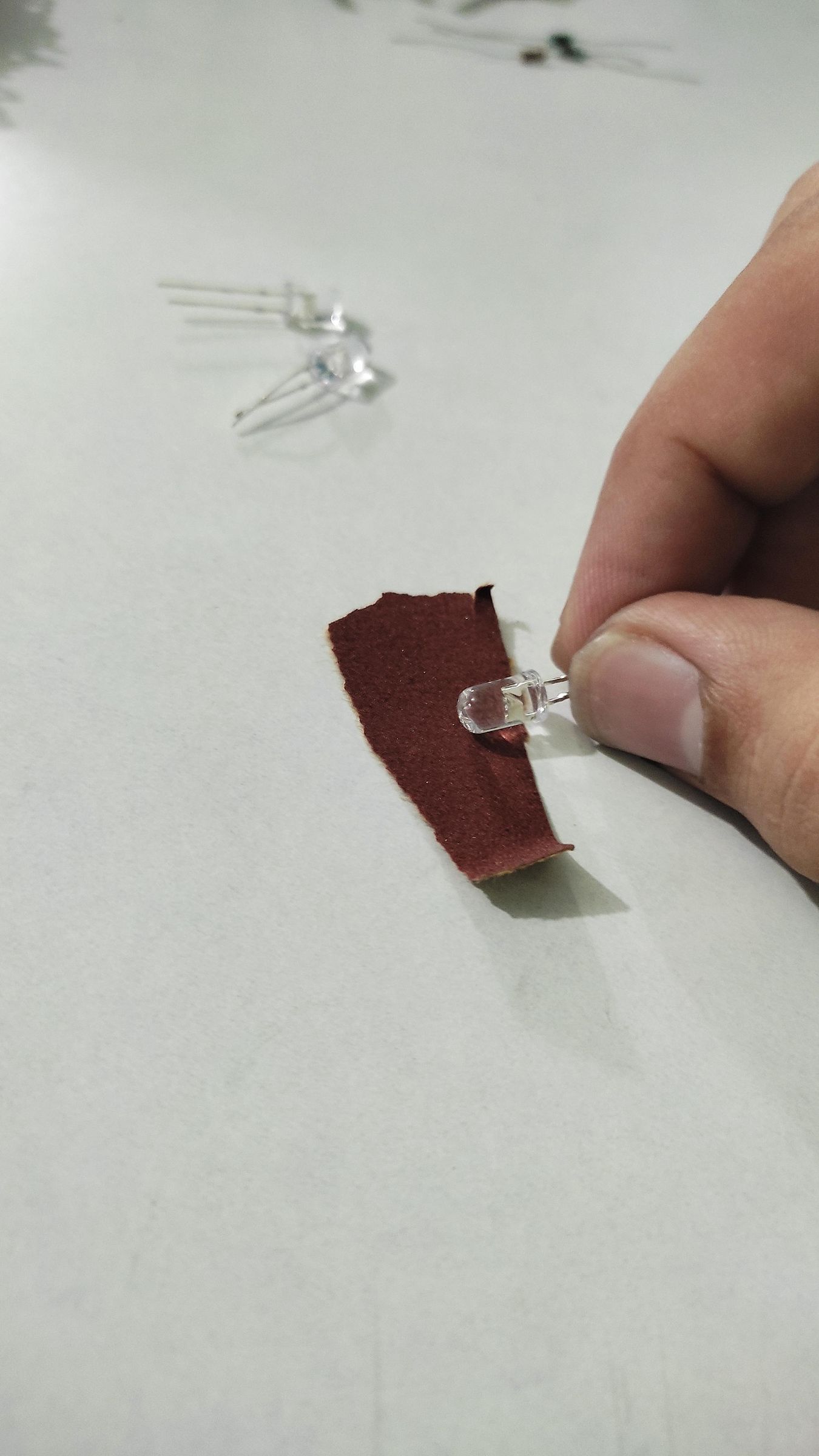
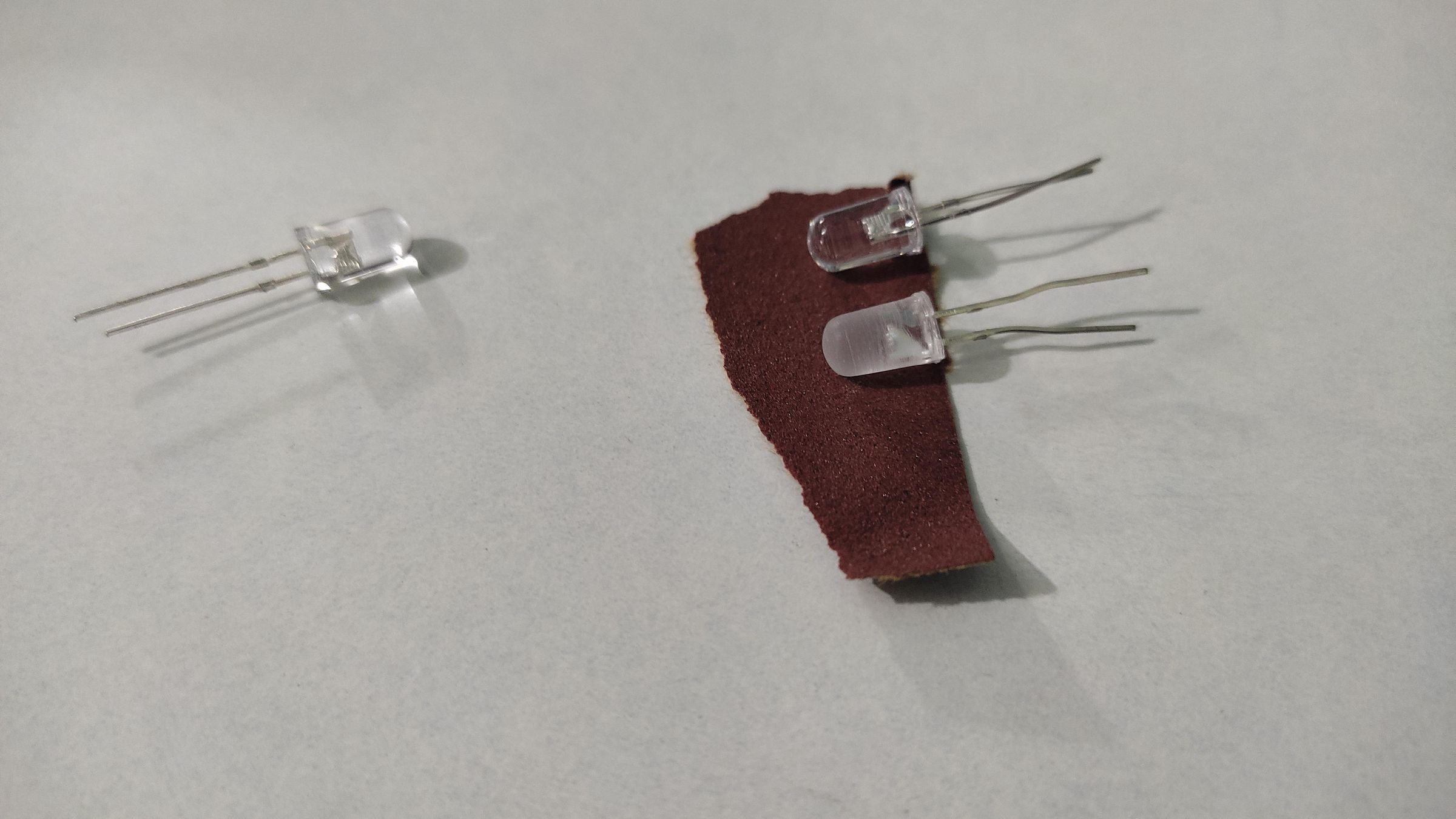
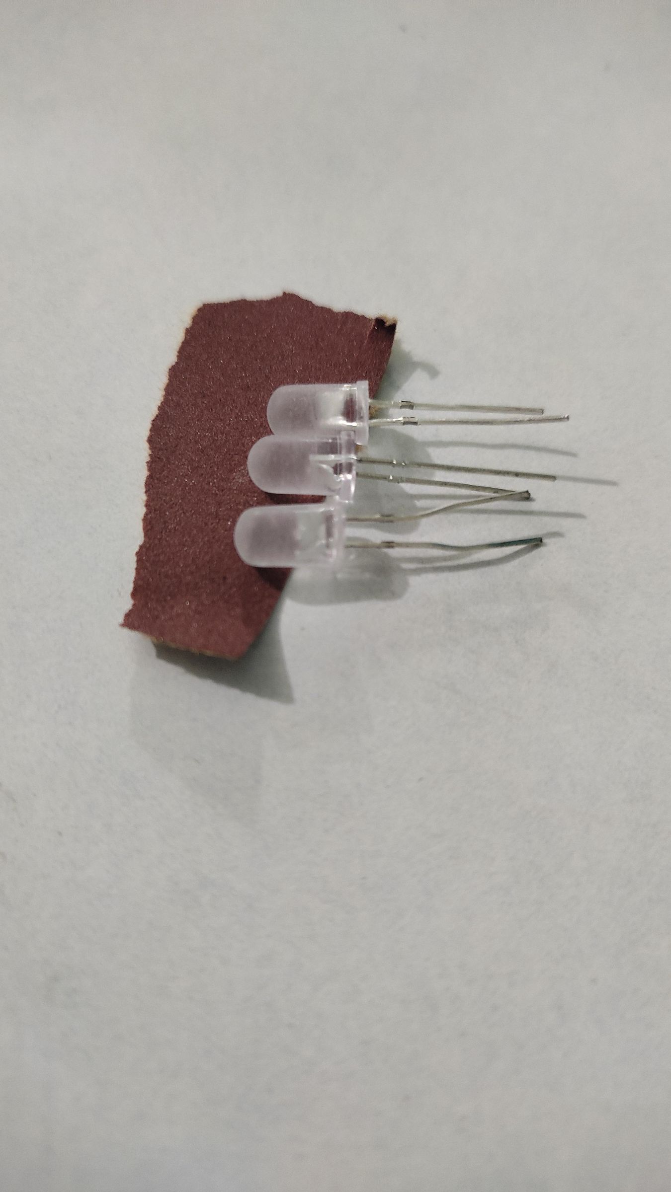
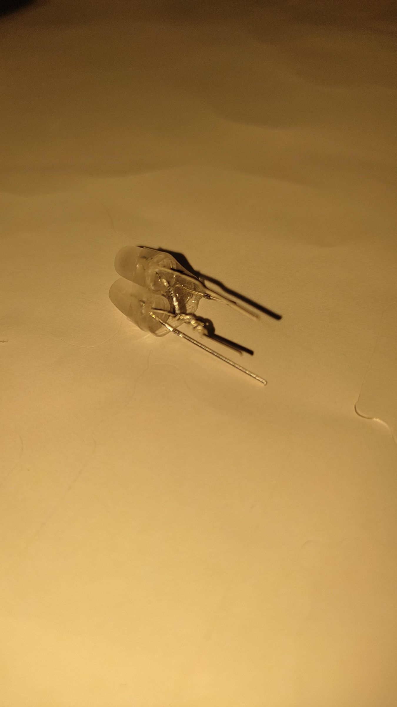
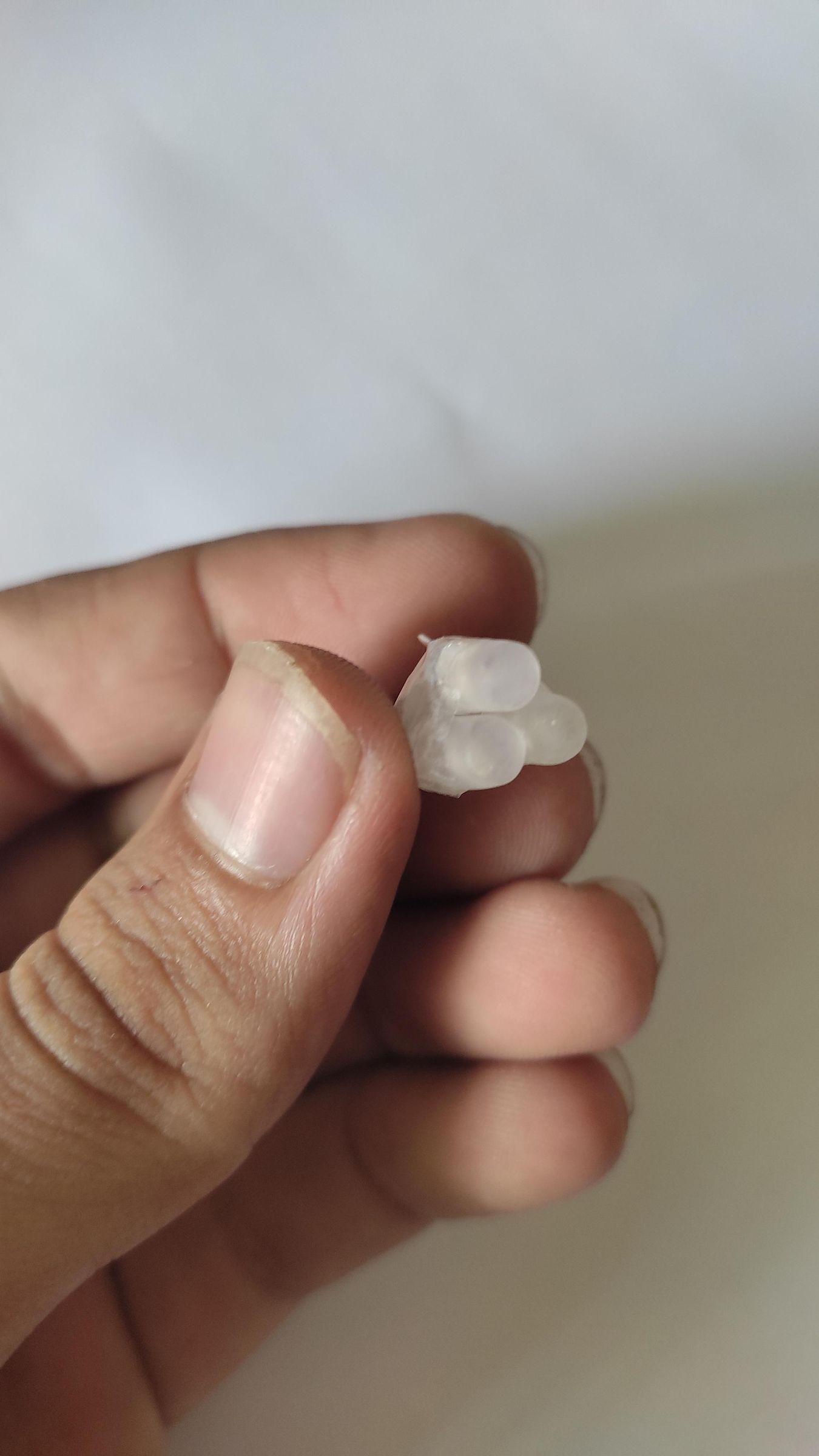
- Now take the three 5mm red, green and blue LEDs and the fine sandpaper (100-400 grit).
- Sand the LED bead as shown in the image.
- Do it with all the 3 LEDs.
- Now take a small piece of clear cello tape and join the three LEDs together.
- Take the cathodes of all the three LEDs and join them by twisting, so that we have a common cathode for the RGB LED.
- The final RGB LED should look like as shown in the last image.
Making the Diffuser
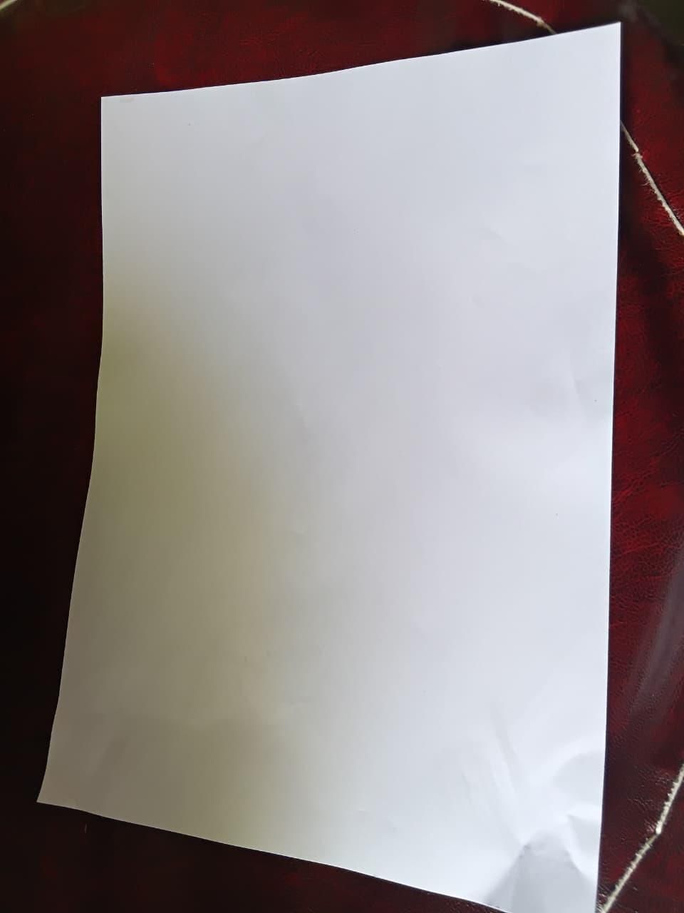
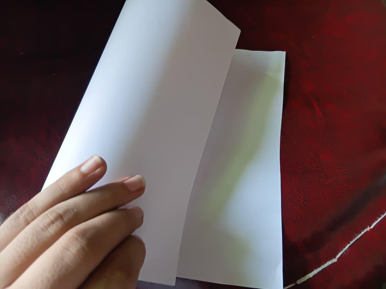
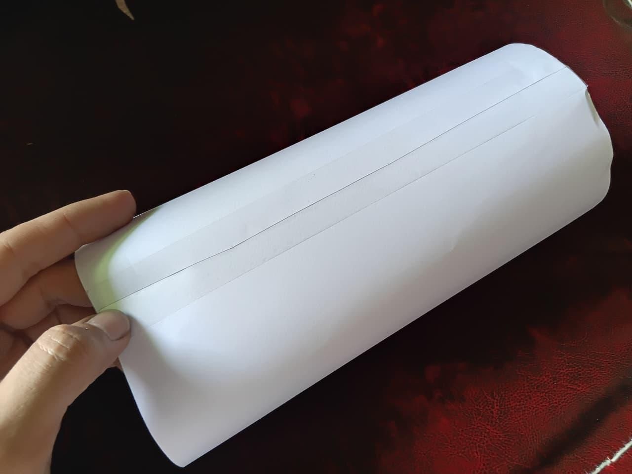
- Now take the A4 Printer Paper.
- Measure its length to about 27 cm.
- Cut the extra length.
- Roll it like as shown in the image.
- Make sure to join them with approximately 5mm width, so as to minimize the light distraction of the diffuser.
Making the Diffuser Circles
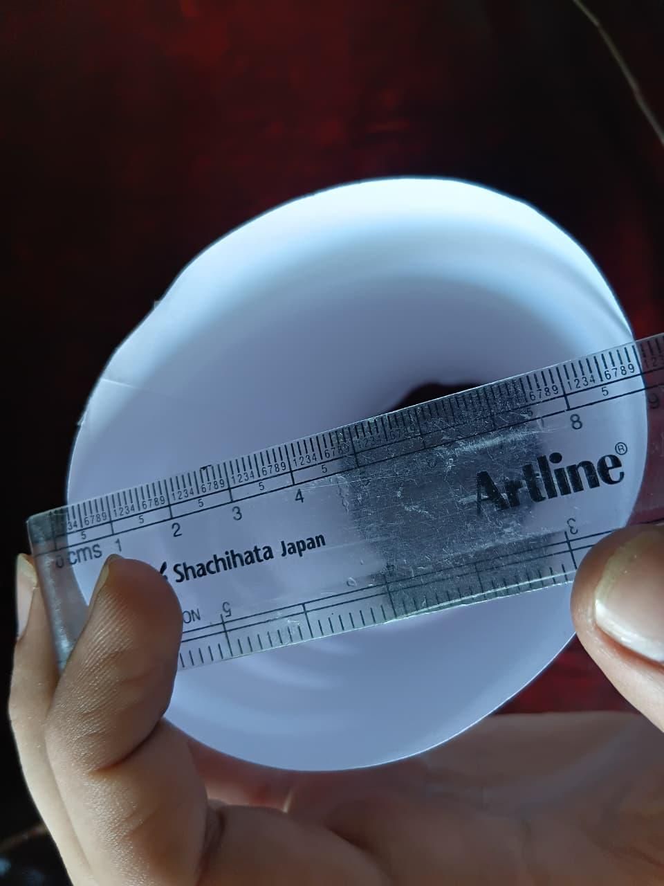
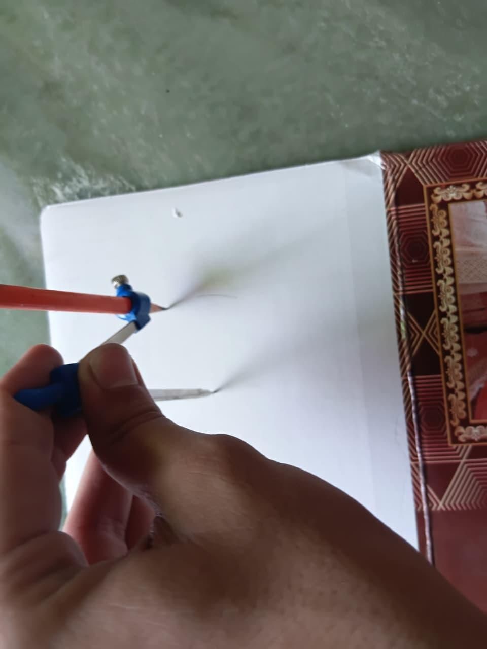
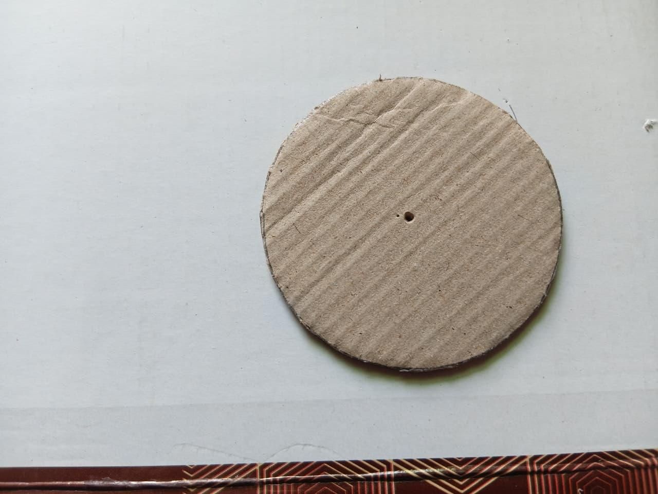
- Now take the diffuser roll, and measure its diameter carefully, in our lengths it came out to be approximately 8.2 cm, radius is 4.1 cm.
- Now take a compass to draw the circle on Cardboard.
- Cut the circle, we need two circles for our diffuser.
Making the Internal Reflectors
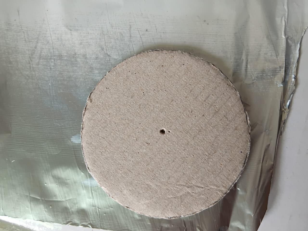
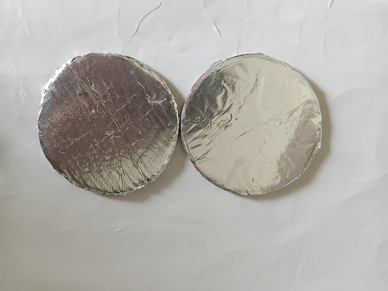
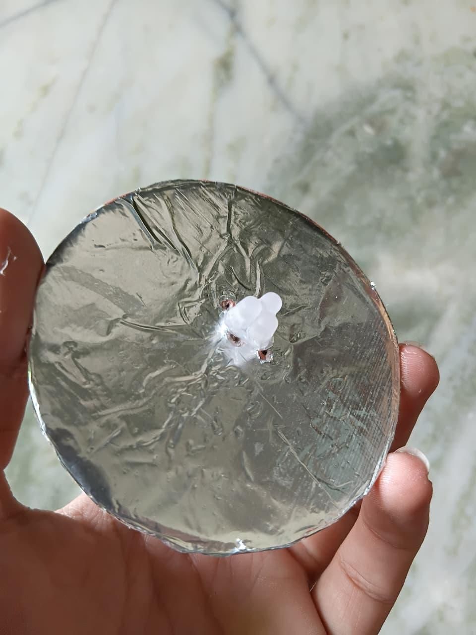
- Now apply glue on one side of both the circles
- Paste aluminium foil on that side.
- This side will face inside of the diffuser cylinder, as to maximize reflections inside the diffuser to get a more dispersed light.
- Now mark the holes for our RGB LED.
- After that, put the led in the circle, and apply glue on its base, so as to secure it.
- Let it dry completely.
Closing the Diffuser
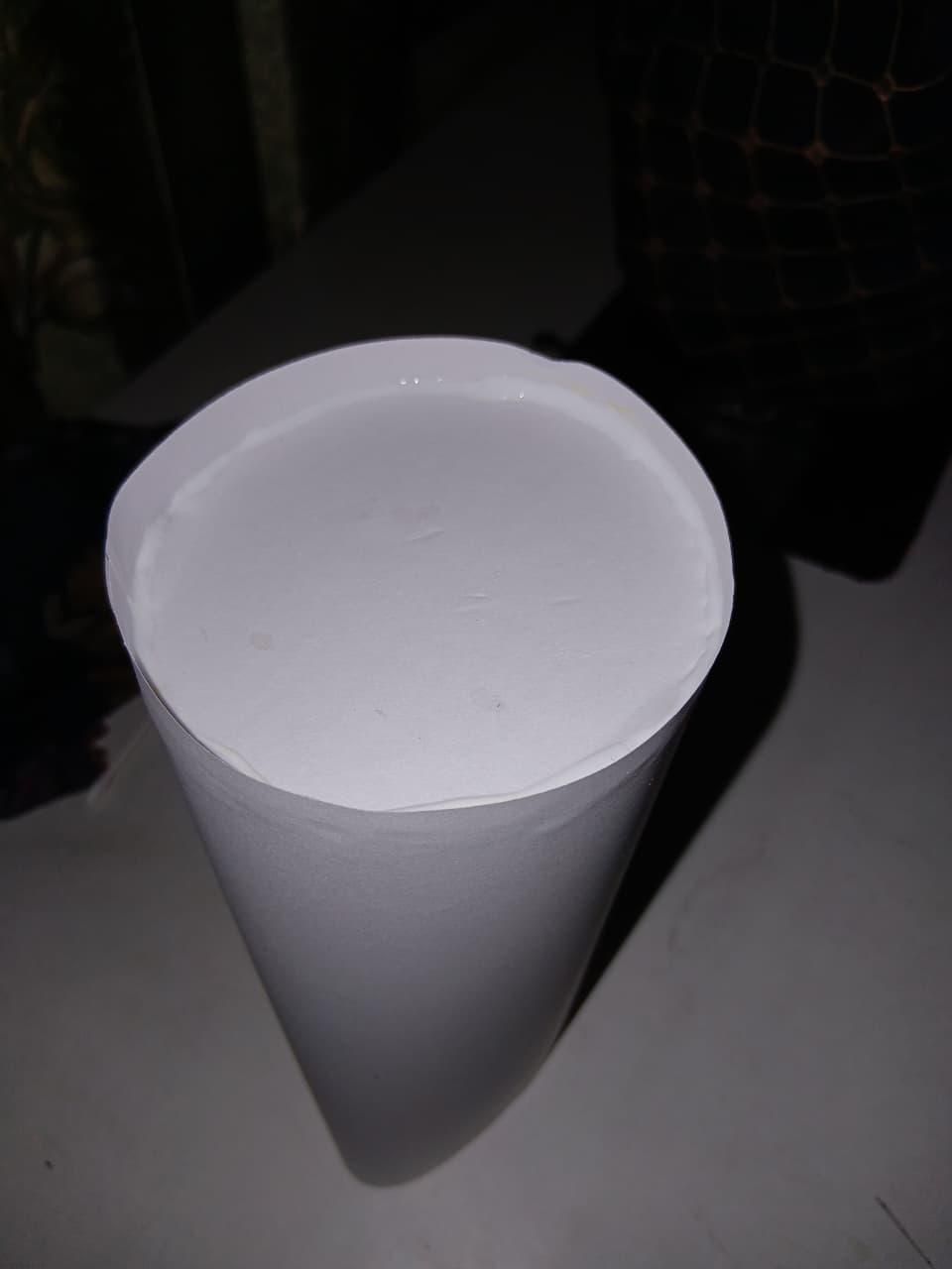
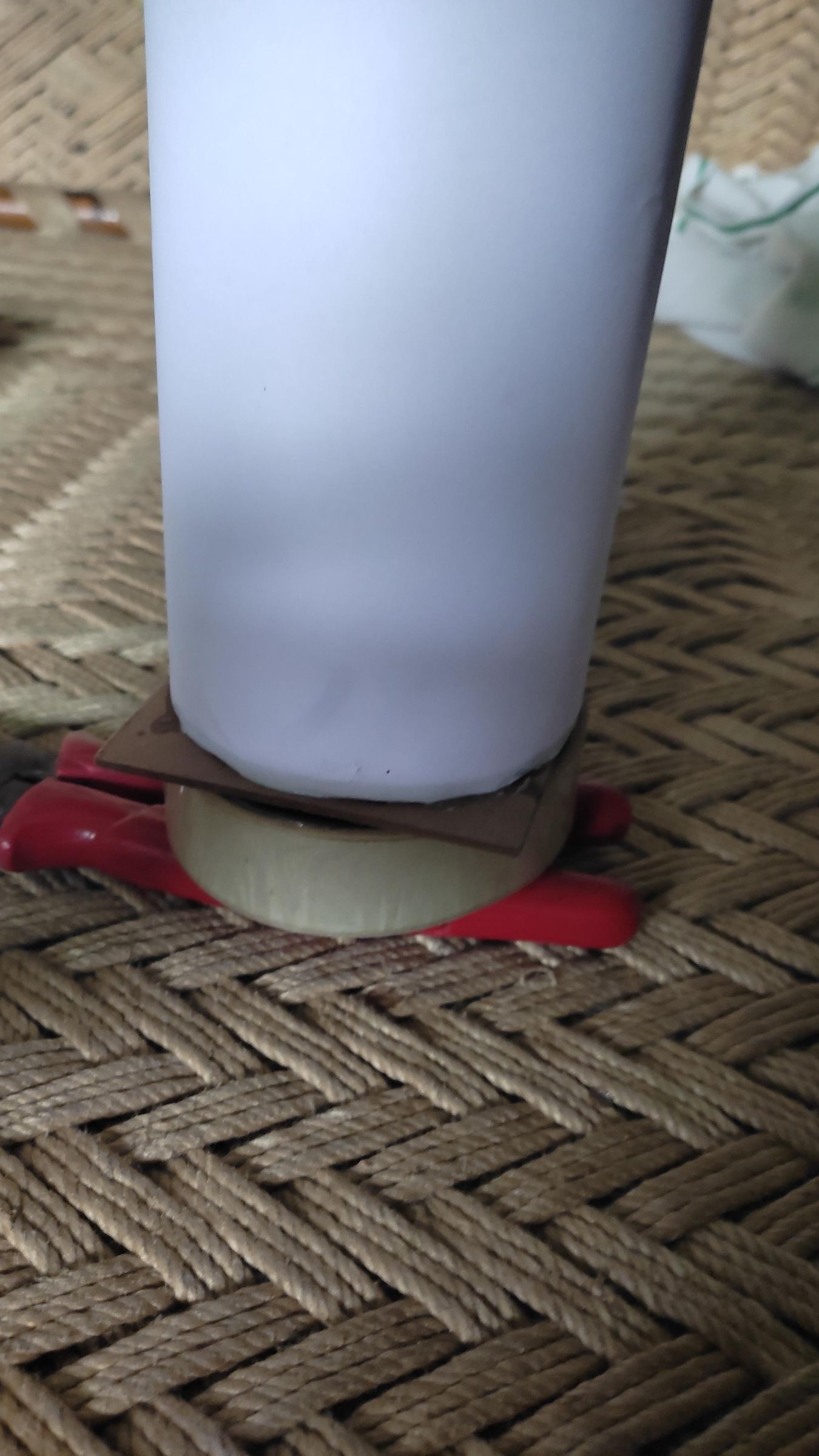
- Now take the diffuser roll, and the two circles.
- Carefully insert one circle on the one end of the diffuser roll.
- Let it dry completely.
- After it dries completely, take the RGB LED circle, and carefully insert it to the leftover end of the diffuser roll.
- Apply white glue on both the circles from outside so as to secure them in place (we are not using superglue here because it makes the paper hard and leave a permanent mark on it, which affect the look of the diffuser).
- Let both of the ends dry completely.
Wiring the Pots
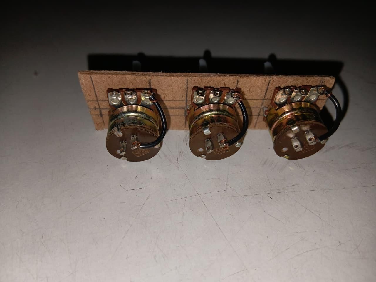
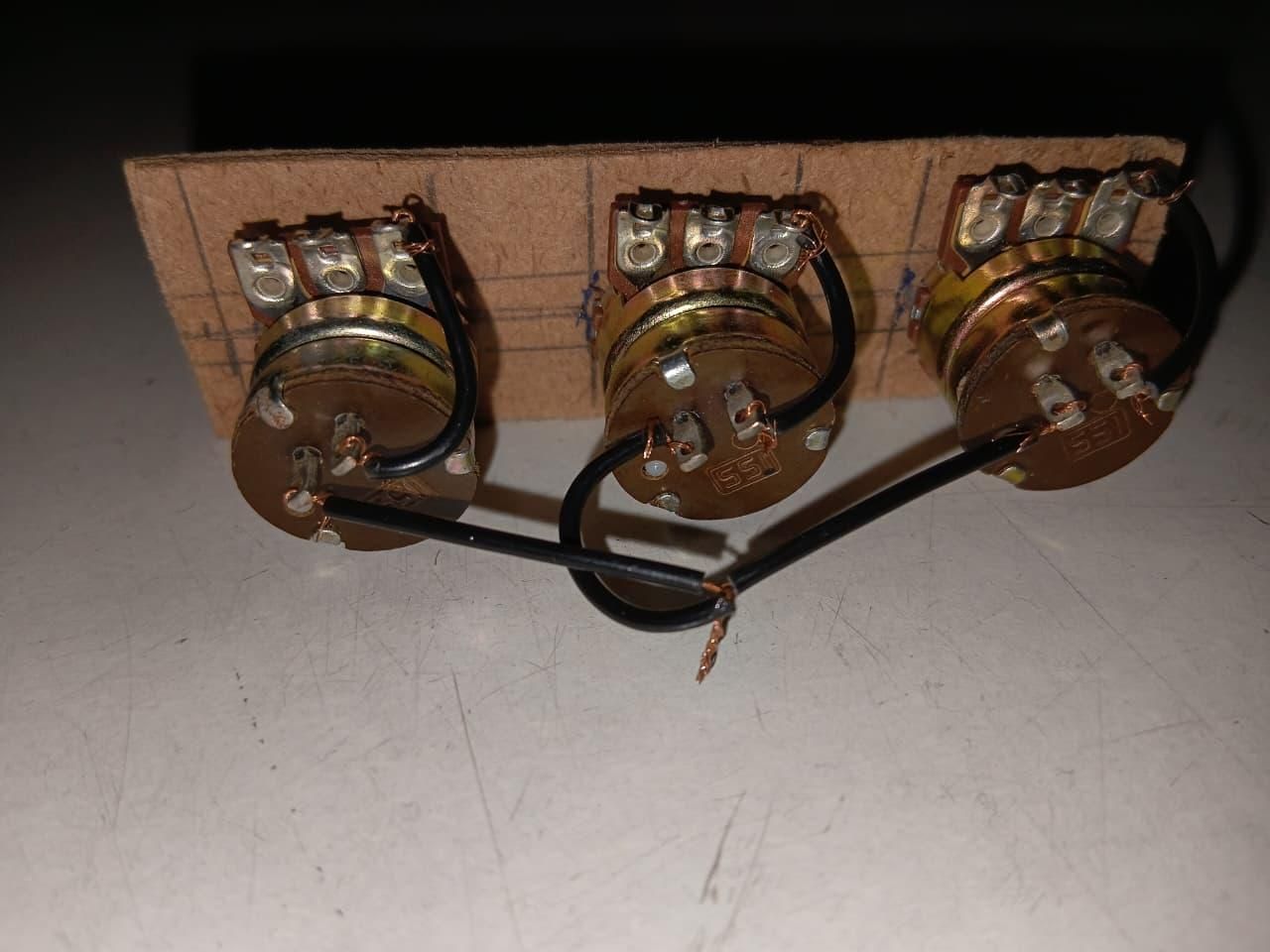
- Now take the pots we structured earlier.
- You will see three pins on the side of the pot, and two pins underneath the pot, the two lower pins are for the inbuilt switch.
- Now take a wire of the required length.
- Scrape off the insulation from the two ends.
- Connect one end to one of the lower two pins.
- Connect the other end to the third pin to the right (when the three pins are facing downwards).
- Do it with all the pots.
- Now take other three wires of the required length.
- Scrape off the ends.
- Connect one end to the leftover downward switch pins and leave the other end free.
- Do it with all the pots.
- Now take the three free ends, and join them together, this will be the VCC, or Positive input.
Note: To eliminate fluctuations in the output it's recommended to solder the joints and insulate them.
Connecting Resistors and Power System
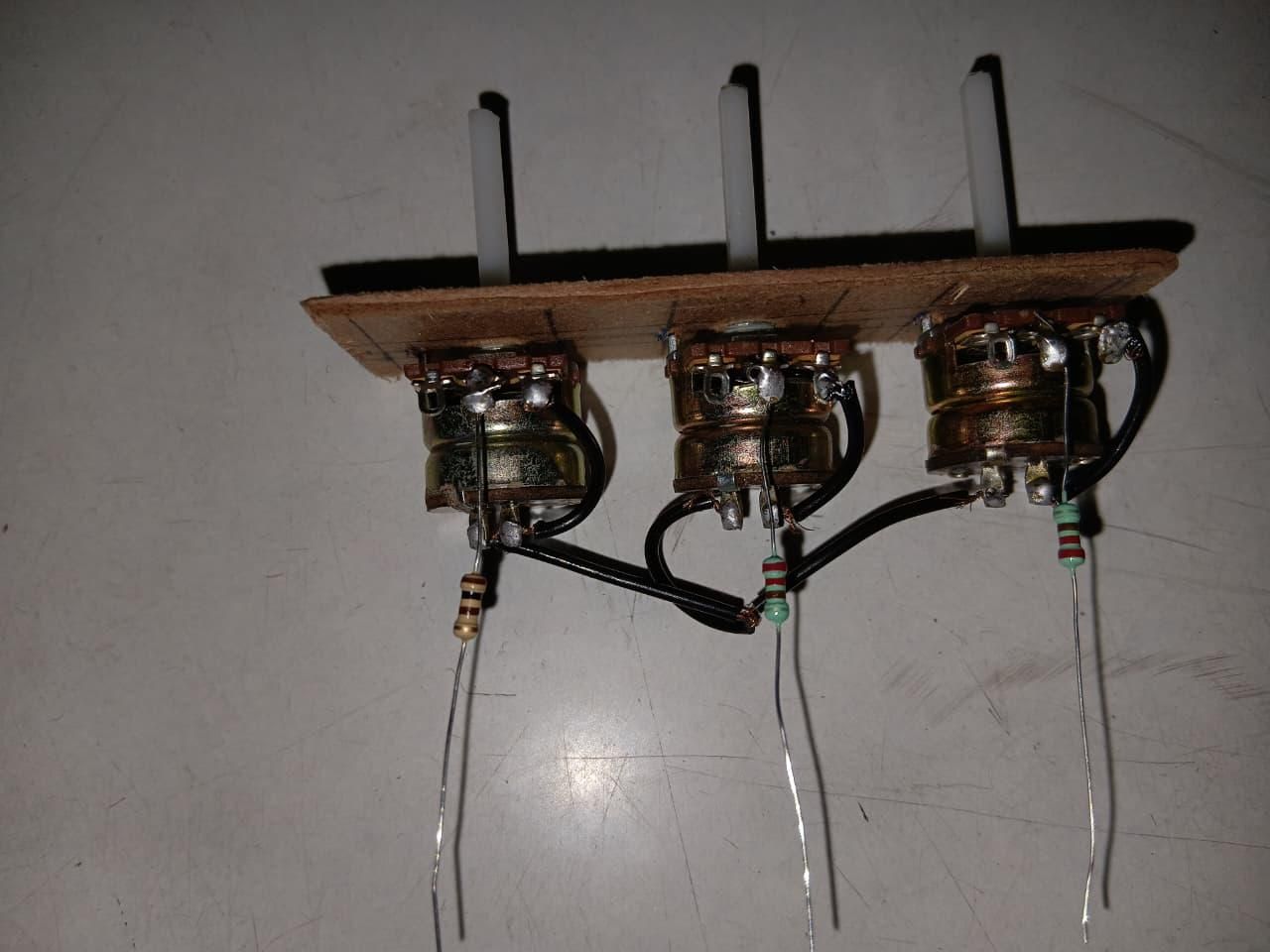
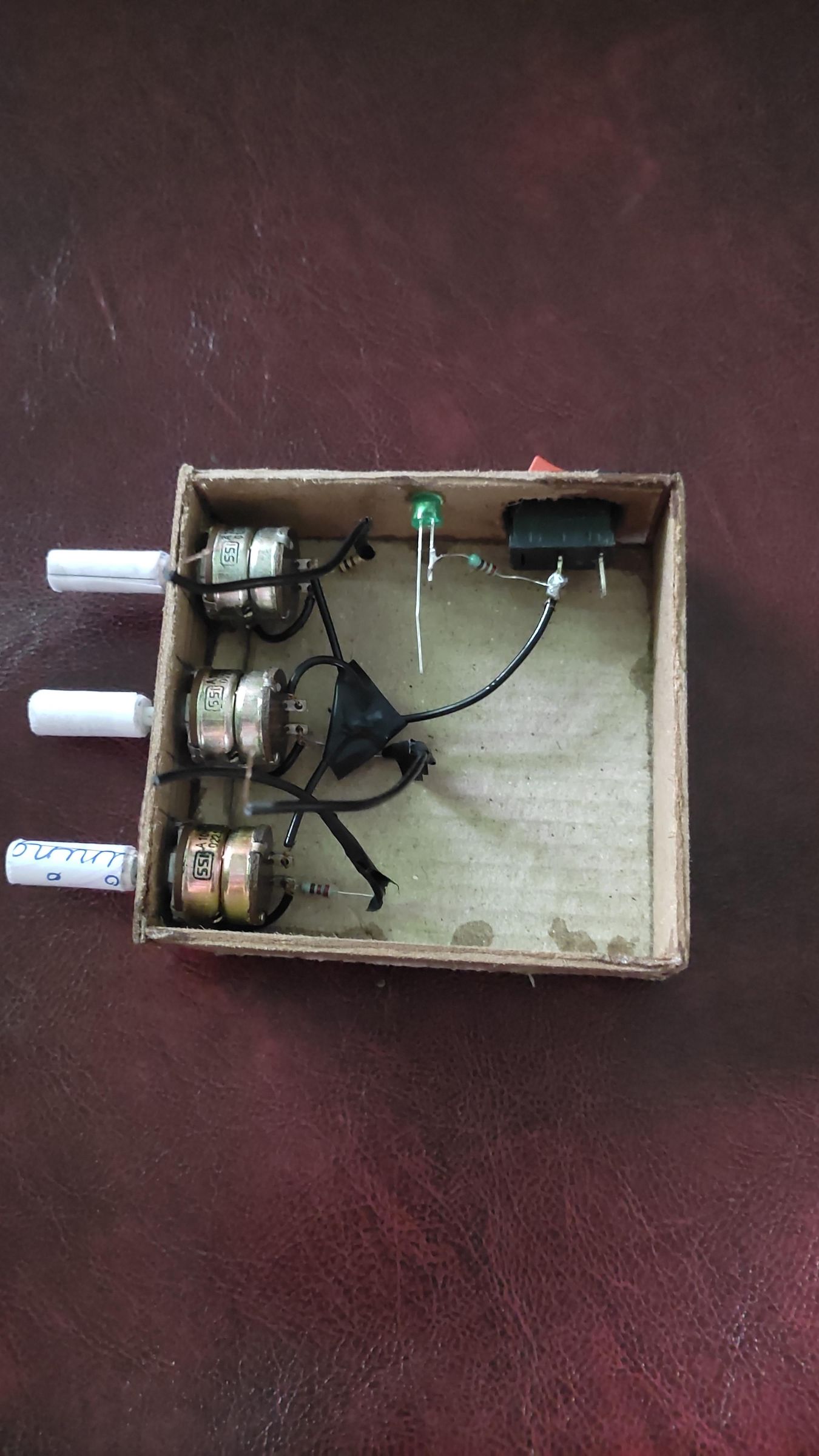
- Now take your 100 Ohm, 3 * 220 Ohm resistors, indicator LED and Rocker Switch.
- In order to make the pots in RGB order follow:
- Connect the 100 Ohm resistor to the left most pot as seen by placing the knob side towards us, this will protect the Red LED.
- Connect the two 220 Ohm resistors to the rest of the two pots, they will protect the Green and Blue LEDs.
- To make the Power System:
- Take one of the side panels of the base, draw markings for the Rocker switch and the indicator LED.
- Carefully cut out the markings.
- Put the switch and the LED in their respective positions and secure them.
- Solder the last 220 Ohm resistor to the anode of the indicator LED and its other end to one of the switch pins.
- Take the red wire of the battery clip and solder it to the other empty pin of the switch.
- take the black wire of the battery clip and solder it to the cathode to the indicator LED.
Note: To eliminate fluctuations in the output it's recommended to solder the joints and insulate them.
Making Knobs for Pots
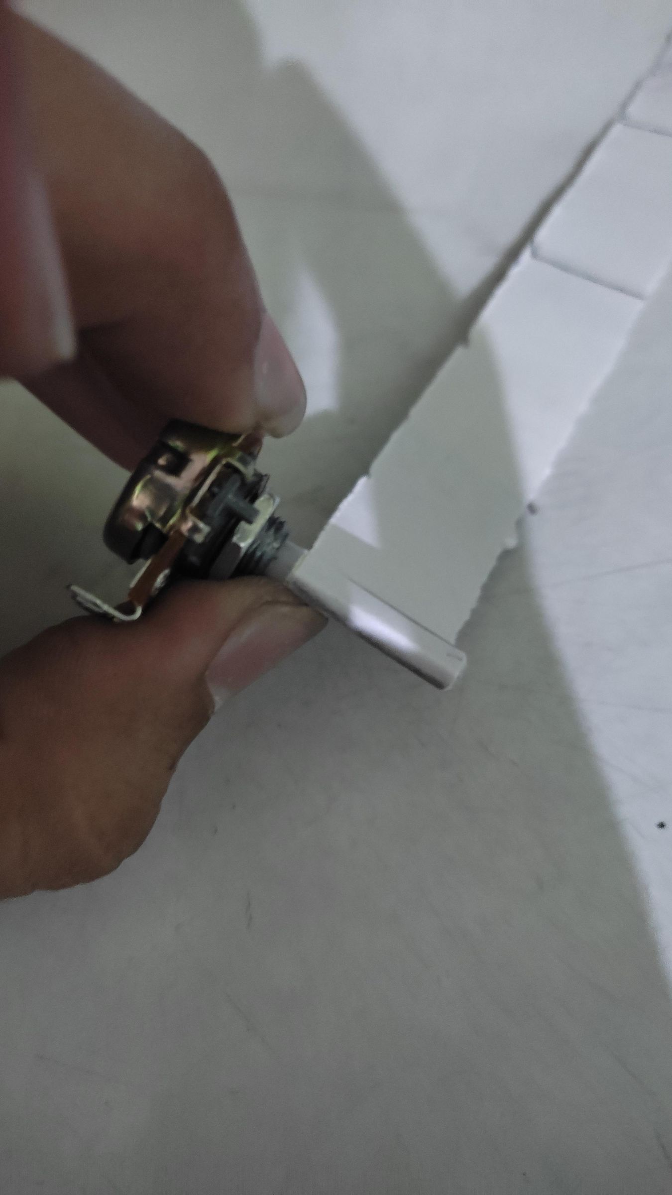
If you already have knobs for the pots, then its ok. But in case if you don't have, then you can make them use this process:
- Take a 2cm broad strip of A4 Paper and roll it tightly around a pot's white narrow knob.
- Finish up the rolling, then seal it using tape or glue.
- Then take some superglue and carefully put it on the ends of the knobs while maintaining the shape of the knobs to secure the shape of the knobs.
- Sand the ends of the knobs to make them better.
- Color the knobs as you like or just apply black or any color insulation tape, to make it sleek.
- Then Attach the Knobs.
Connecting the Diffuser to the Base
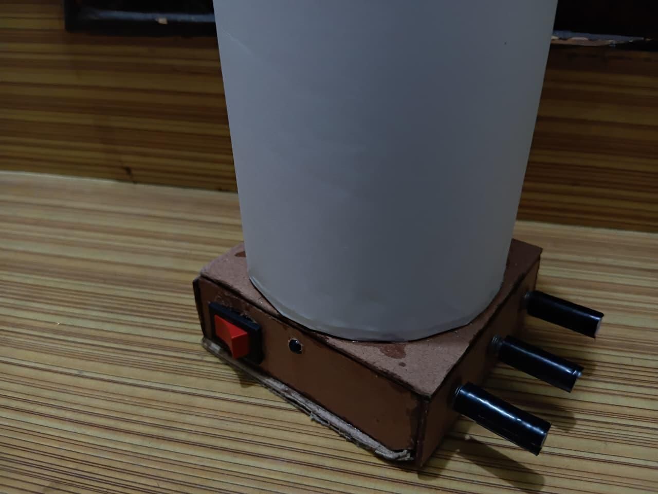
Connecting the diffuser to the base is very easy!
You can also elongate the legs of the LEDs if you feel they are too short, by soldering some insulated wire.
The connection is simple:
- Firstly, identify the anodes of red, green and blue LEDs.
- Then solder them to their respective resistors and secure the connection.
- Now take the common cathode of the three LEDs and solder it directly to the indicator led cathode where the battery clip's black wire is soldered too.
- Now connect the battery, the circuit is complete!
Note: To eliminate fluctuations in the output it's recommended to solder the joints and insulate them.
Testing
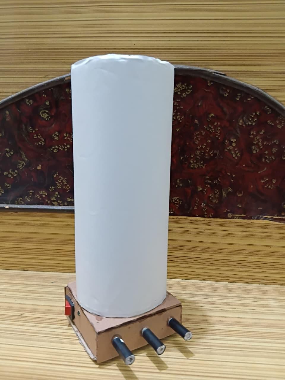
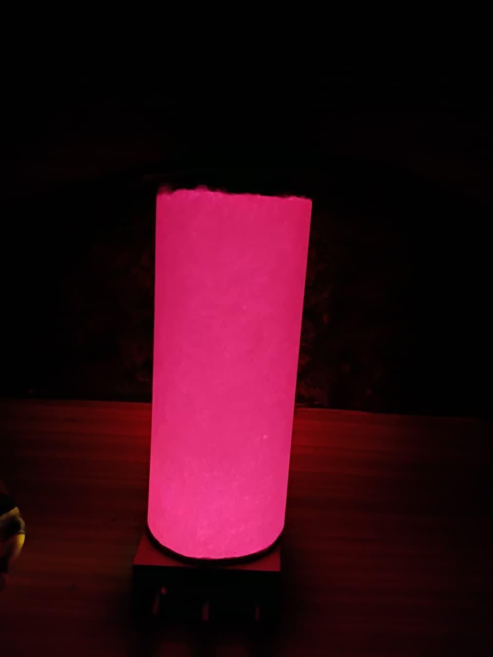
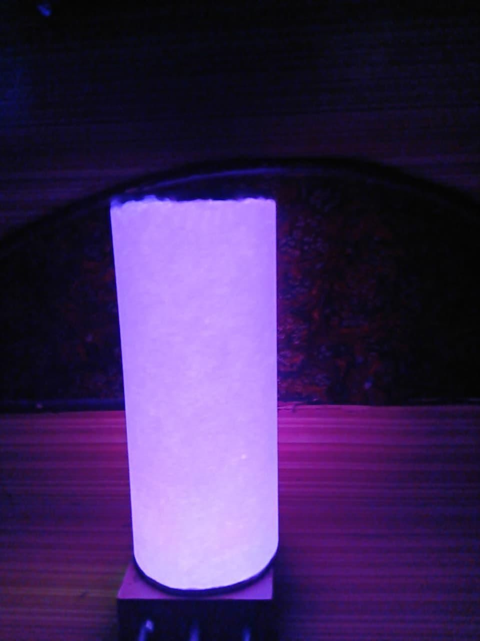
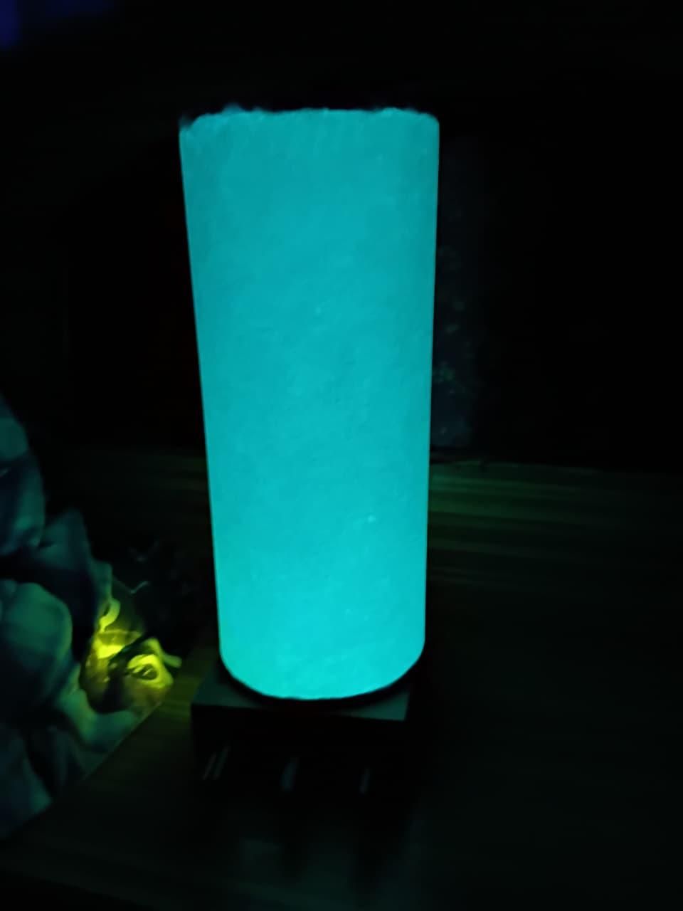
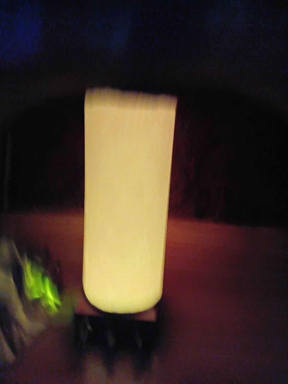
Before you secure anything in place, it's always better to test it.
Check that all the knobs are working perfectly, and all the LEDs are also working perfectly.
Check for any loose connections, if found secure them, as loose connections may lead to fluctuations in the light.
After testing that all the things are working perfectly fine, then secure the base as you like i.e. to secure the base with superglue or with white glue (white glue will take longer time to dry, whereas superglue will dry very fast, but it is easy to remove the panel from the base pasted with white glue, as superglue may damage the base).
Conclusion and Thank You!
- Thank you so much for taking the time to read through my pure analog column lamp build!
- Fabricating a fully functional lighting project using freeform, dead-bug circuitry with zero circuit boards was an incredible engineering challenge.
- I am absolutely thrilled with how the sleek, minimalist A4 paper cylinder diffuses the balanced light wavelengths into a smooth, seamless gradient.
- If you enjoyed this hardware-driven layout and found these steps helpful, please consider leaving a comment and sharing your own version.