The Smart Lighting of the Maréchal Bridge
by 23kn162si in Circuits > Microcontrollers
127 Views, 0 Favorites, 0 Comments
The Smart Lighting of the Maréchal Bridge
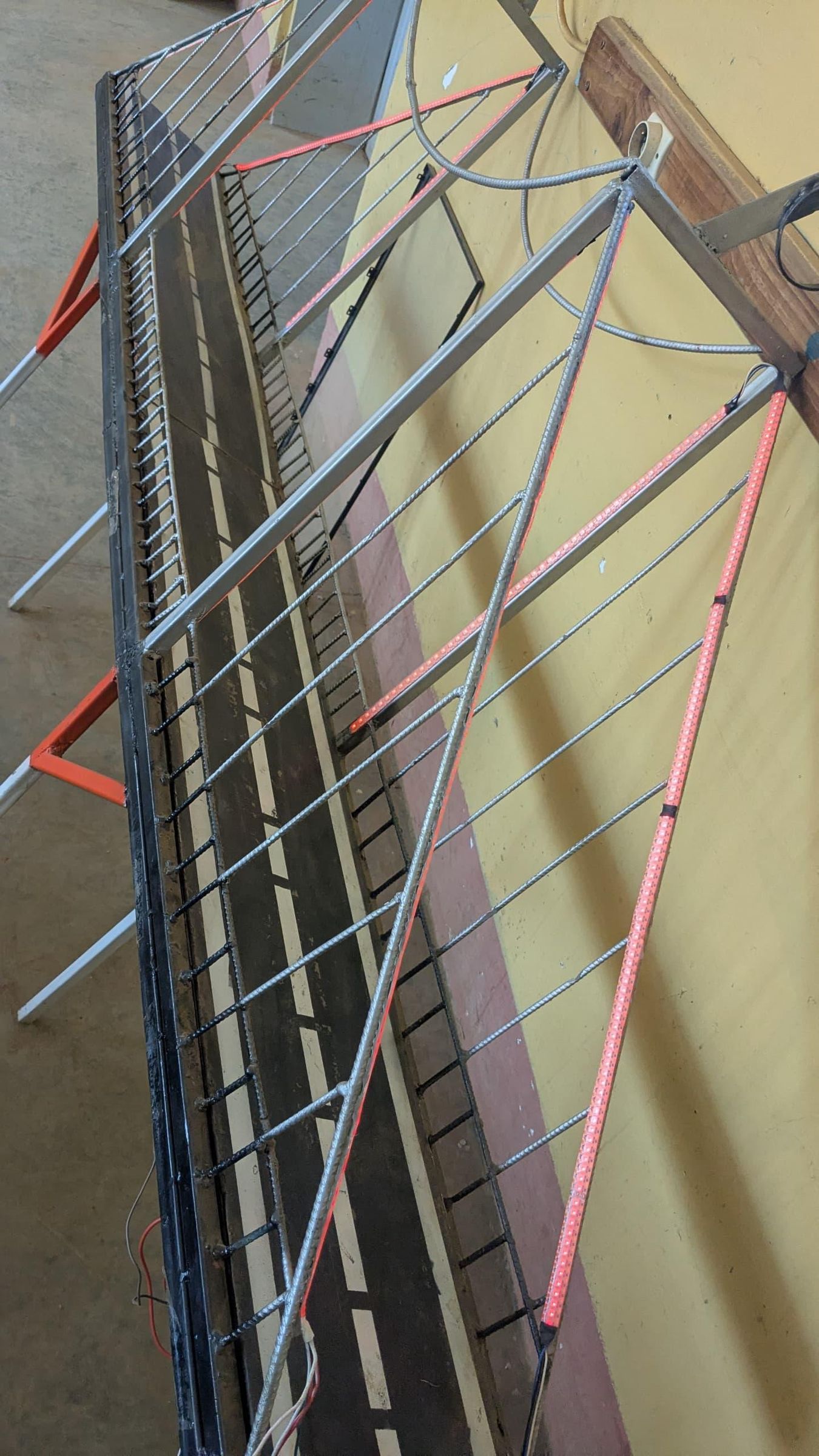
This project presents the design of the smart architectural lighting for the Maréchal bridge, a fully automated system built around an ESP32 microcontroller. By leveraging the ESP32's Wi-Fi connectivity, the system provides real-time control and the ability to instantly switch between different lighting scenarios from a visual interface accessible via a computer or a smartphone.
By combining IoT for remote supervision, programmable electronics, and the structural mechanical engineering skills behind the model, this prototype offers a modern, energy-efficient, and interactive solution for modernizing civil infrastructure
The Maréchal bridge (officially renamed the Matadi bridge) is a strategically suspension bridge of 722 meters long located in the Democratic Republic of the Congo. Built 43 years ago (in 1983), it spans the Congo River at the city of Matadi. In our country, it is considered a vital economic lifeline due to the massive flow of commercial transactions that cross it daily. This bridge is unique: it stands as the only fixed link connecting the capital Kinshasa and the interior to the main seaports of the Atlantic Ocean. This model serves as a tribute to this African steel giant
Supplies
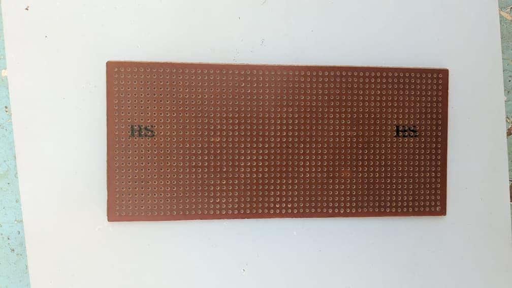
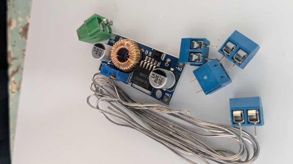
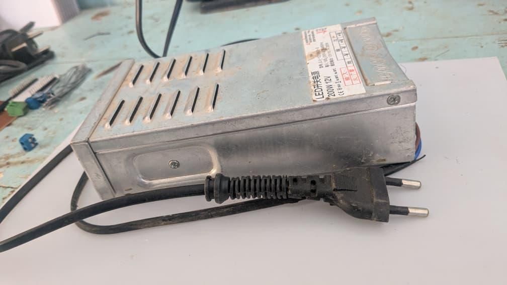
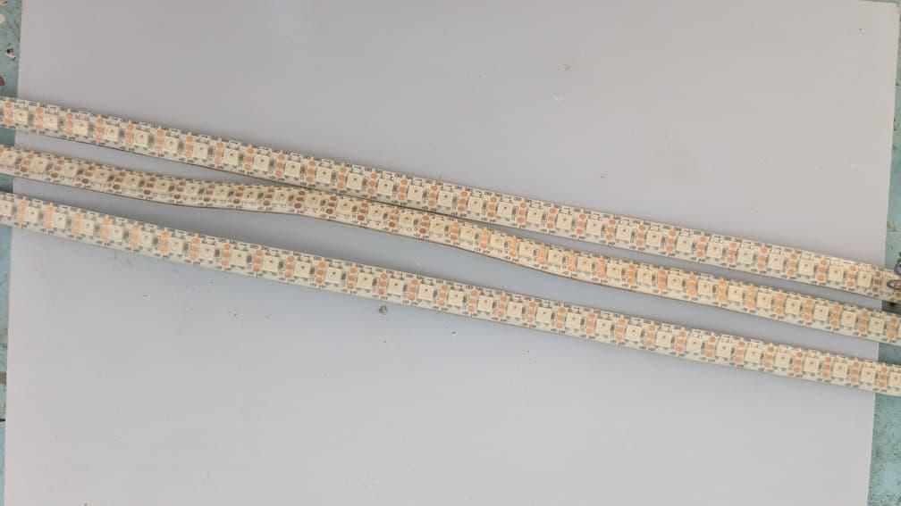
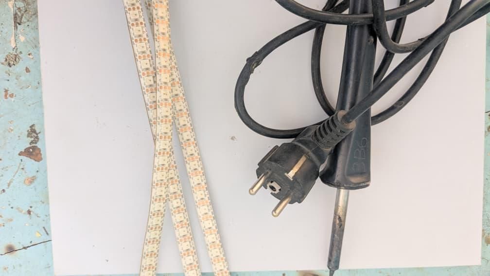
Important note on the structure: Although this project focuses around the model of the Maréchal bridge, its mechanical manufacturing steps will not be detailed here. The metal structure had already been fully built beforehand by the students in mechanics. When I discovered the theme of the Rainbow Colors competition, I was instantly inspired by this bridge. I wondered how to leverage IoT and programmable electronics to make it more flashy, more visible, and give it a second technological life
Hardware & Electronic Components
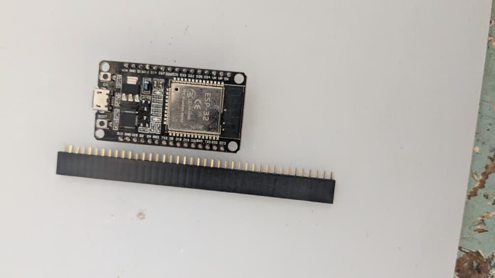
- ESP32 Microcontroller: I chose it for its Wi-Fi connectivity
- Addressable RGB LED Strips: to control each light point independently and create the rainbow effect
- Power Supply: Allows to deliver the necessary current to stable-power all LEDs without voltage drops
- Jumper wires: Conducting wires to ensure power and signal connections
- Screwdriver
- Measuring device (Multimeter): Essential to check the measurement
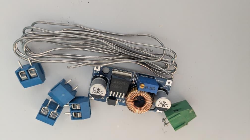
- DC-DC Step-Down Buck Converter Module: Used to step down and stabilize the voltage from the main power supply to safely power the ESP32
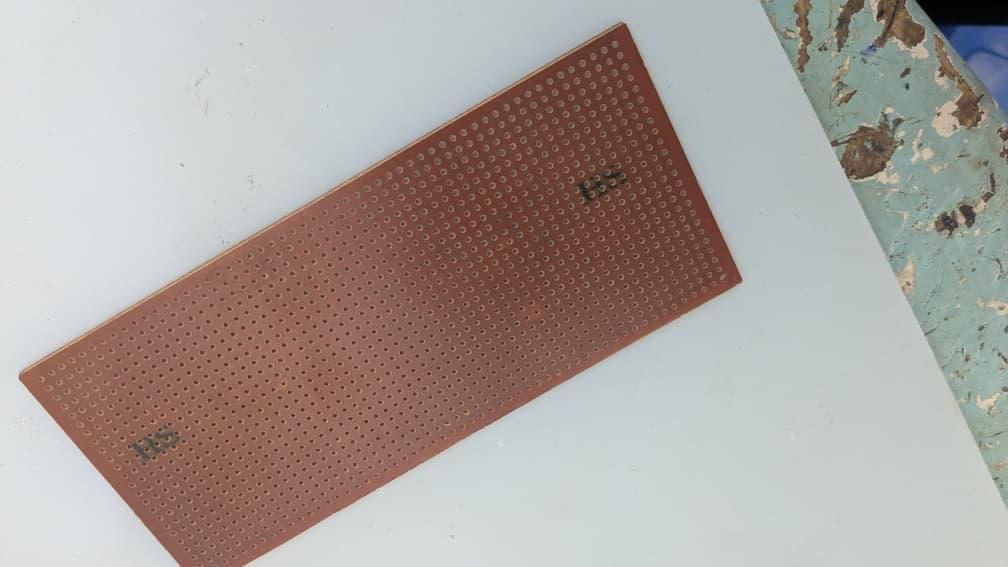
- Perfboard: physical base to solder electronic components
- Screw Terminal Block: Connector that allows to connect power wires
Operating Principle
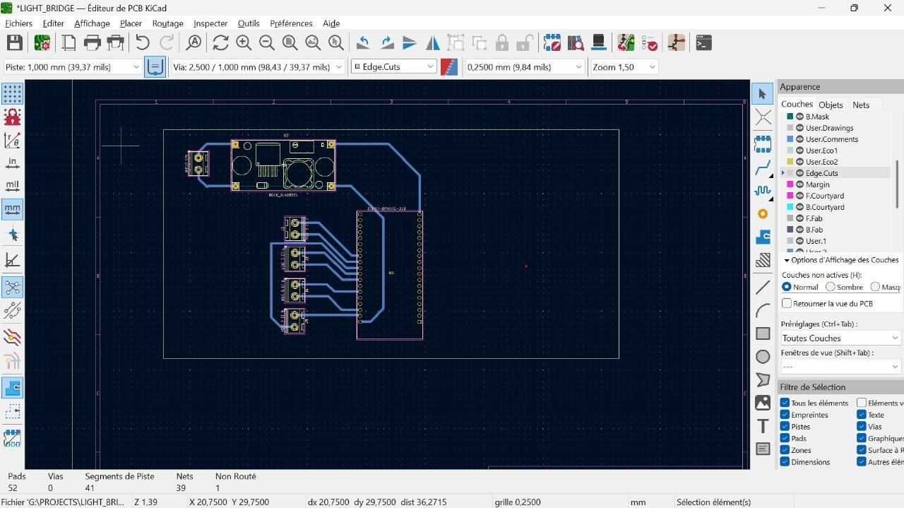

The operating principle is based on additive synthesis
Additive synthesis is the physical principle that allows recreating all colors of visible light by mixing the three primary hues: Red, Green, and Blue. This remarkable physical phenomenon was a huge source of inspiration for me in this project, especially since the flag of my country, is itself a beautiful blend of different meaningful colors.This desire to bring a vibrant spectrum to life pushed me to exploit this optical property to artificially reproduce the entire rainbow on our model. In practice, the microcontroller is the true mastermind behind this lighting magic. It operates as an ultra-fast digital conductor, sending coded electrical signals along the circuit. By precisely varying the dosage and electrical intensity of each tiny red, green, and blue chip inside the strips, the microcontroller instantly merges these three primary lights to create the perfect illusion of a single color or a smooth chromatic transition in motion, capable of freezing its path as soon as my smartphone commands it to
Operating Diagram
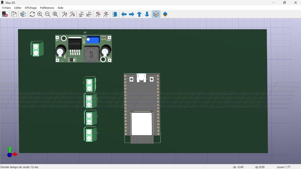
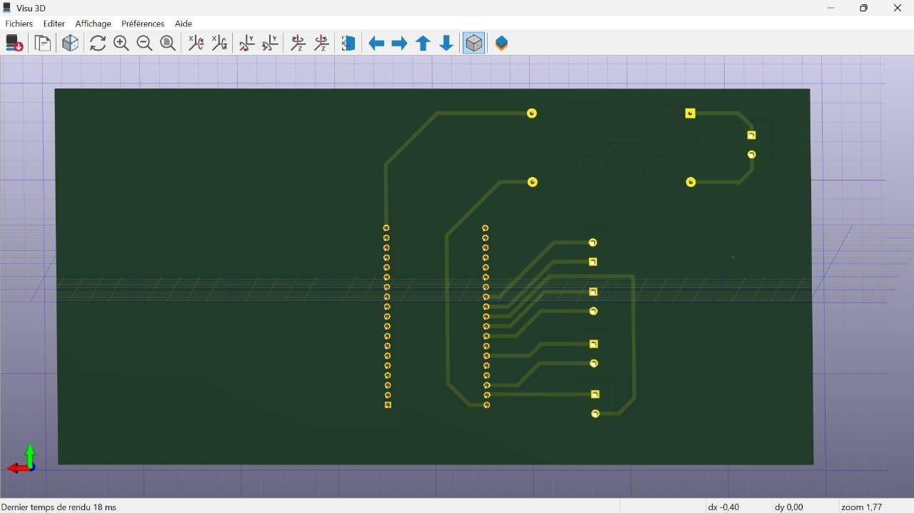
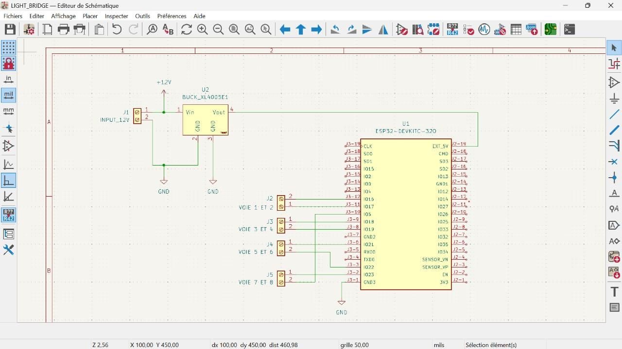
I used KiCad version 8.0 to create my schematic. My WS2812B addressable LED strips distributed across the 4 control channels of the ESP32. I chose an external 12V supply rather than a direct connection to the 3.3V pin of the ESP32 because I had to meet a crucial electrical power constraint. My project uses WS2812B model addressable LED strips totaling a large number of light chips to illuminate simultaneously (160 LEDs per channel). The 3.3V pin of the ESP32 is only designed to power small logic sensors. It is totally incapable of providing the necessary current to make such a quantity of LEDs shine under its nominal voltage. If I had attempted to connect these strips directly to the ESP32, the microcontroller would have directly overheated and burned out due to the electrical overload. As I used an external 12V power source dedicated for the LEDs, each pixel receives the necessary energy to shine at maximum brightness without ever soliciting the internal power circuits of the ESP32. This is at this level that I brought in the step-down voltage regulator (Step-Down). The ESP32 being a very sensitive electronic component, it is powered by 5V and cannot withstand a direct 12V supply voltage on its pins without being destroyed. The regulator serves as a safety barrier: it recovers the strong 12V voltage from the main power supply and lowers it stably to the exact 5V voltage required for the microcontroller. And I have the power line (12V) and the control line (5V).
Detailed Operation
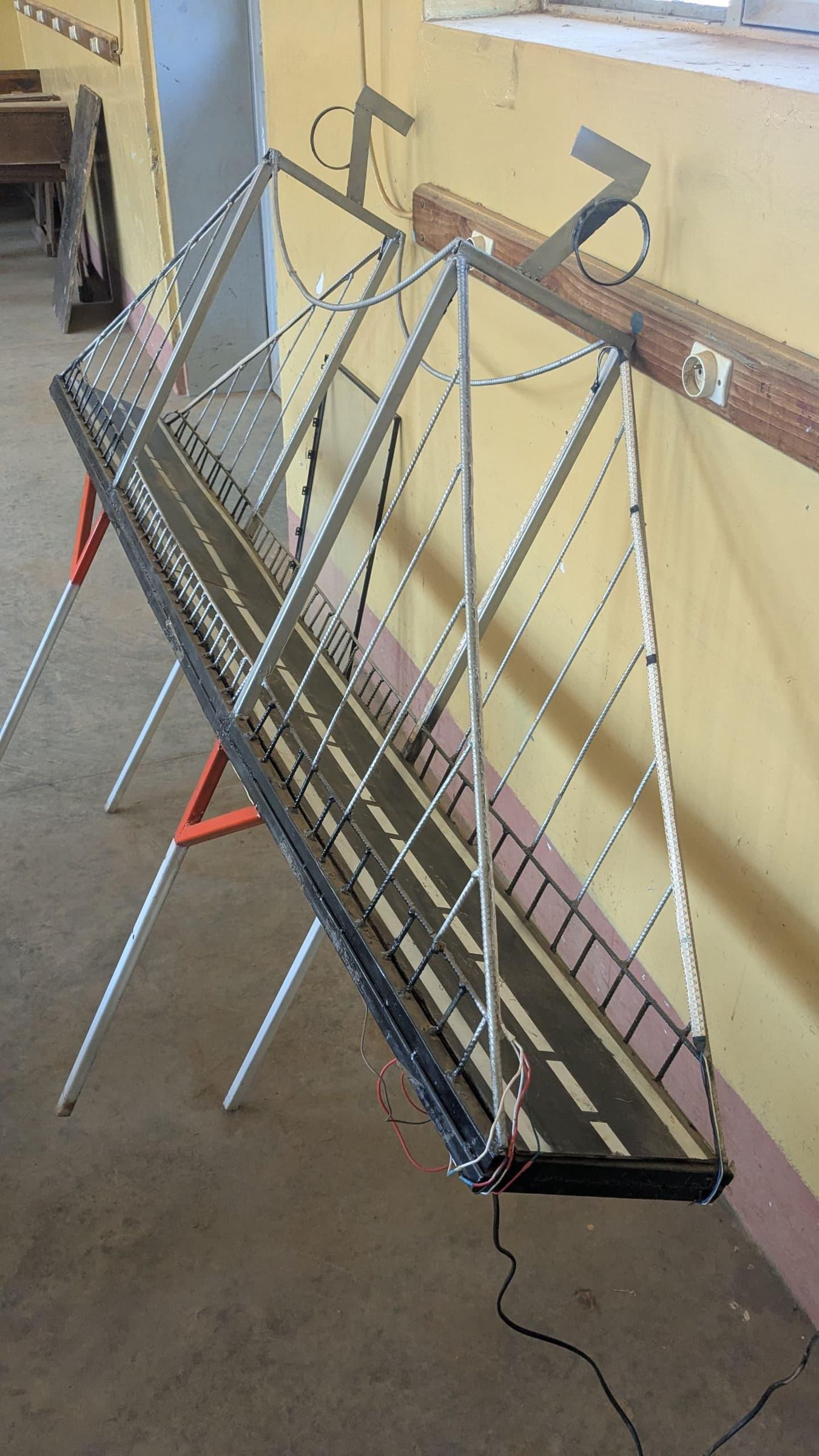
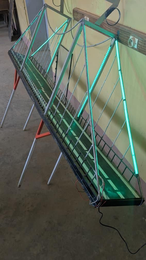
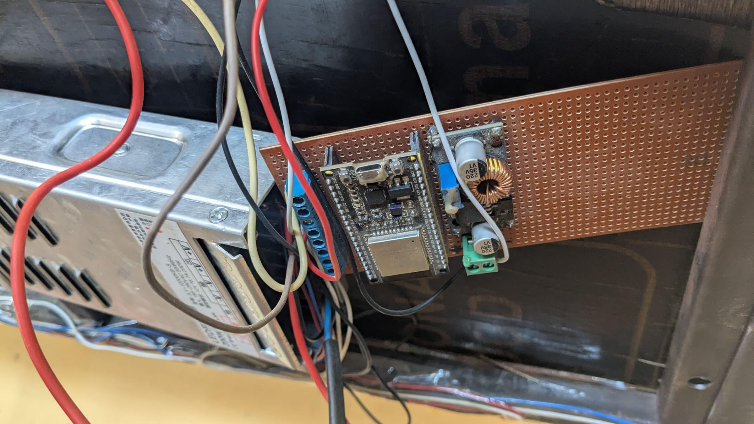
For this setup, I separated the power section from the control section to protect my components:
- From Main Power Supply to Regulator: I connected the V+ and V- outputs of the main power block directly to the IN+ and IN- input terminals of my step-down module.
- From Step-Down Module to ESP32: After adjusting the converter to get a stable 5V, I ran wires from the OUT+ and OUT- terminals to the VIN (5V) and GND pins of the ESP32 using the screw terminal blocks on my perfboard.
- Powering the LED Strips (Parallel): To avoid voltage drops across the setup, I wired the power for the strips in parallel on the 12V rail. The main lines distribute the current to each strip: the positive pole goes to the VDD pin and the negative pole to the VSS pin.
- Control Signal Injection: For color control, I linked the digital pins of the ESP32 directly to the data inputs of the bridge lines. The control signal is injected independently via pins GPIO 16, 17, 18, and 19, each corresponding to a specific channel in our system
- Data Management per Channel: The data flows autonomously on each of the 4 hardware channels defined in the program. Each channel handles its own daisy-chained series of pixels (up to 160 LEDs per line). The signal enters through the DIN pin of the first LED and propagates to the end of the line, leaving the last DOUT output open
- Common Grounding: To eliminate signal noise and ensure a stable logic reference, I tied the GND pin of the ESP32 and all VSS pins of the strips to the exact same negative power rail
Programming
Here is the link to the GitHub repository
Microcontroller Coding
The logical source code and the implementation of these libraries are located exclusively within the main src/main.cpp file
For the software implementation, I skipped the basic Arduino IDE and chose a more professional setup: VS Code paired with the PlatformIO ecosystem. PlatformIO provides powerful environment configuration management, making it easy to build C++ embedded systems, manage libraries, and configure our ESP32 target board dynamically
The microcontroller source code relies on three strategic open-source libraries:
- FastLED (Lighting Scenography): A highly flexible and performant library widely used in commercial applications. It provides advanced functions to seamlessly handle addressable LEDs and compute complex effects. It allowed me to program the smooth transitions required to display the full rainbow spectrum along the bridge structure
- ESPAsyncWebServer (IoT Dashboard Hosting via WebSocket): This library turns the ESP32 into an asynchronous local web server equipped with a WebSocket protocol. When a client device (like a smartphone or laptop) connects to the same local Wi-Fi network and enters the ESP32’s IP address into a web browser, the ESP32 intercepts the request and serves an embedded web interface. Thanks to WebSockets handled in the background by the microcontroller, it enables lightning-fast, real-time user interaction over the bridge's animations without freezing the processor
- ArduinoJson (Data Formatting): To maintain lightweight and rapid communication between the mobile dashboard and the microcontroller's web server, data packet exchange must be structured. I implemented ArduinoJson (v7) to format all commands into standard JSON strings. This ensures seamless parsing of custom color states and sequence overrides on the fly
Dashboard Coding
The source codes describing the initial configuration and the graphical user interface are located exclusively within the data/ folder of my PlatformIO project (data/config.json and data/index.html files)
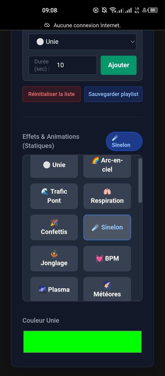
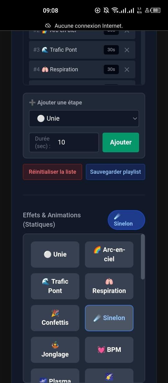
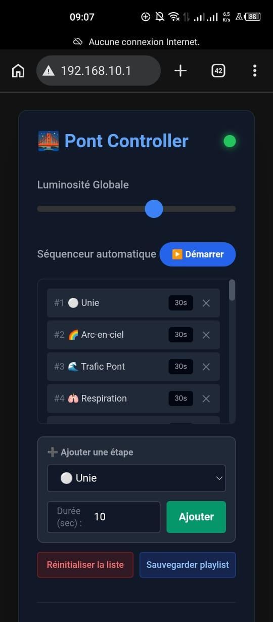
The monitoring interface, hosted on the ESP32, relies on config.json for state persistence (mode, brightness, color) and on index.html for a responsive UI using Tailwind CSS. The embedded JavaScript handles the dynamic update of the 30 effects, a custom animation sequencer, and real-time communication via WebSocket for instantaneous bi-directional interaction.
To take control of the Maréchal Bridge model, the connection procedure follows three local steps:
- Wi-Fi Pairing: The user must first connect their smartphone or computer to the standalone wireless network generated directly by the bridge (SSID: Pont_LED_Controller)
- Authentication: It is mandatory to enter the secure password hardcoded into the microcontroller (password123).
- Accessing the Dashboard: Once connected to the same local network, simply open a web browser and type the default controller IP address (192.168.10.1) to instantly bring up the interactive control dashboard.
Demonstration

Downloads
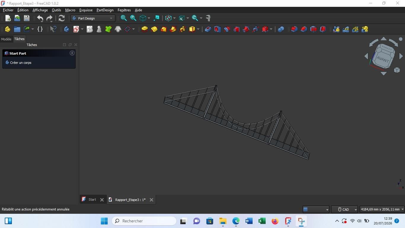
3D Design of the Bridge
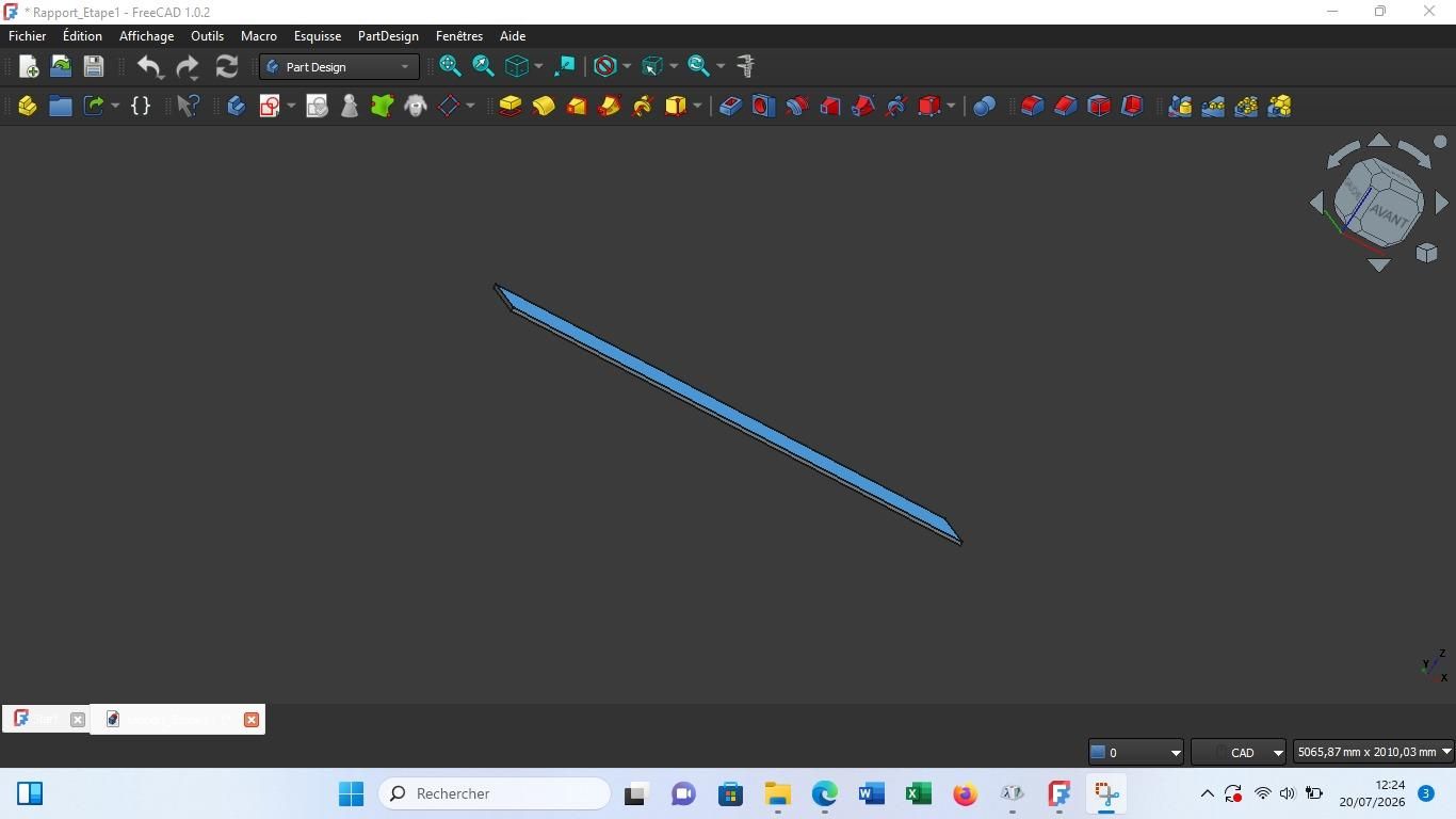
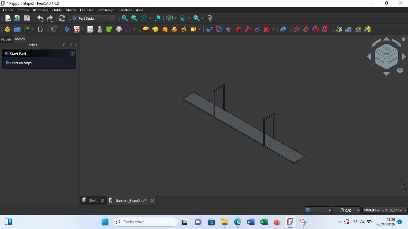
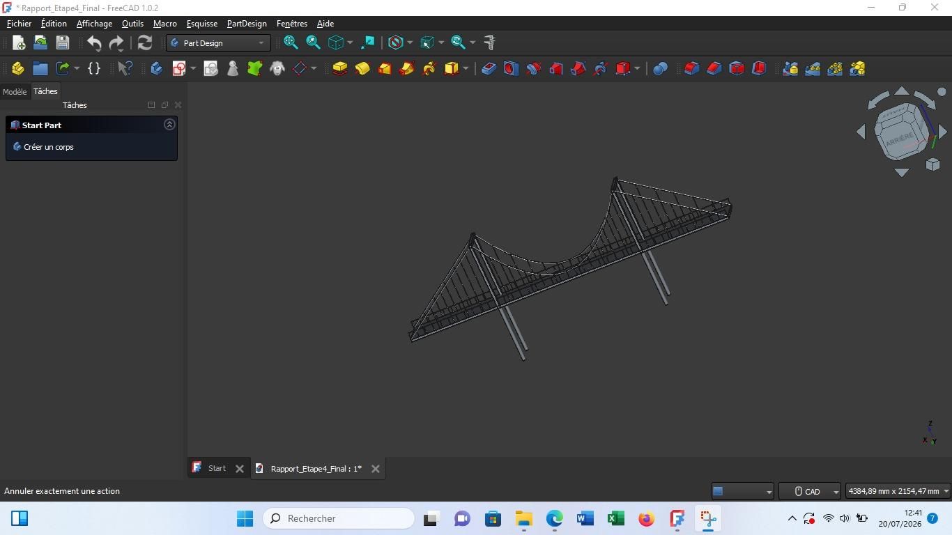

Step 1: Creating the deck
I started by creating the bridge deck by defining its length, width, and thickness. This part forms the base of the entire structure.
Step 2: Adding the towers
Next, I placed two towers on each side of the deck. I chose their height and position in order to ensure the stability of the bridge.
Step 3: Placing the cables and hangers
After that, I added the main cables connecting the towers, and then the vertical hangers that support the deck.
I also created the bracing to reinforce the structure.
Step 4: Finishing touches
Finally, I added the railings, metal reinforcements, and structural details. I then verified the dimensions, corrected any alignment defects, and obtained the final 3D model.
Final Thoughts
This smart architectural lighting project for the Maréchal Bridge has been an exceptional opportunity to bridge theory and practice. By giving a technological second life to an existing mechanical structure, this implementation proves that modernizing civil infrastructure now relies on intertwining engineering fields. Combining the programmable electronics of the ESP32, the power of additive color synthesis, and the flexibility of an asynchronous IoT interface shows that it is possible to create solutions that are aesthetic, interactive, and energy-efficient
Beyond the purely technical aspect, this collaborative work helped me grasp the importance of power distribution and data transmission in a real-world setup. Looking ahead, this prototype paves the way for future improvements, such as embedding vibration or weight sensors directly linked to the dashboard. This would allow the interface to monitor the structural health of the bridge in real time, while automatically shifting the lighting scenarios based on traffic flow or safety alerts