The Ultimate Macro Pad-Keyboard Hybrid: Capacitive Slider, Thumbstick, and Wheel Integration
61 Views, 1 Favorites, 0 Comments
The Ultimate Macro Pad-Keyboard Hybrid: Capacitive Slider, Thumbstick, and Wheel Integration
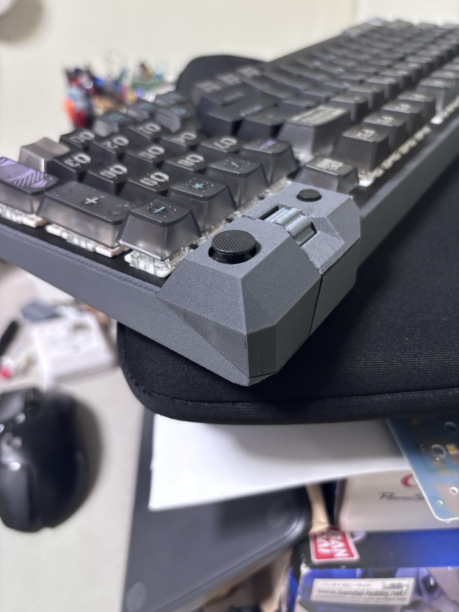
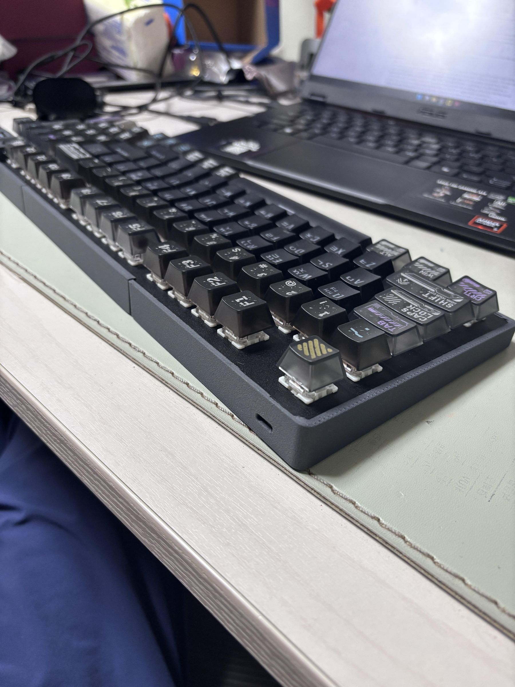
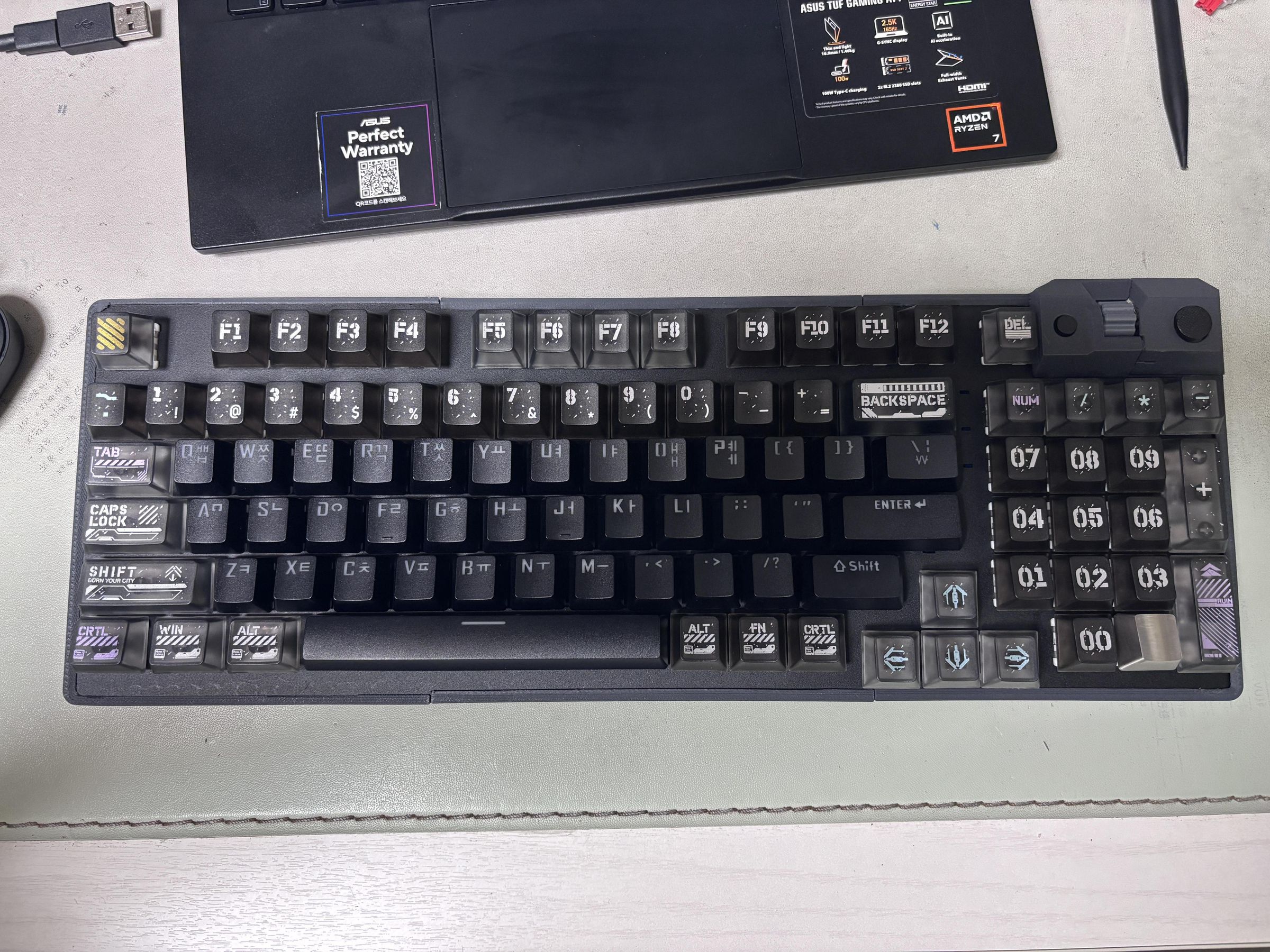
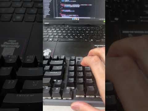
This project is about modding a keyboard by integrating a custom FPCB capacitive electrode array, an analog joystick, and a rotary encoder.
To be honest, the original goal was simply to fix a broken keyboard and add a few mods along the way. But I quickly realized that modding a perfectly functional keyboard from scratch would have been much easier. And I did. While cramming a custom PCB inside the keyboard housing, I recognized that starting with a custom enclosure would make life a lot simpler.
Consequently, this project utilizes the core PCB of an existing keyboard (the Lenovo Aurora GK10 98-key layout) while incorporating custom-built components and a fully custom enclosure.
Key Features:
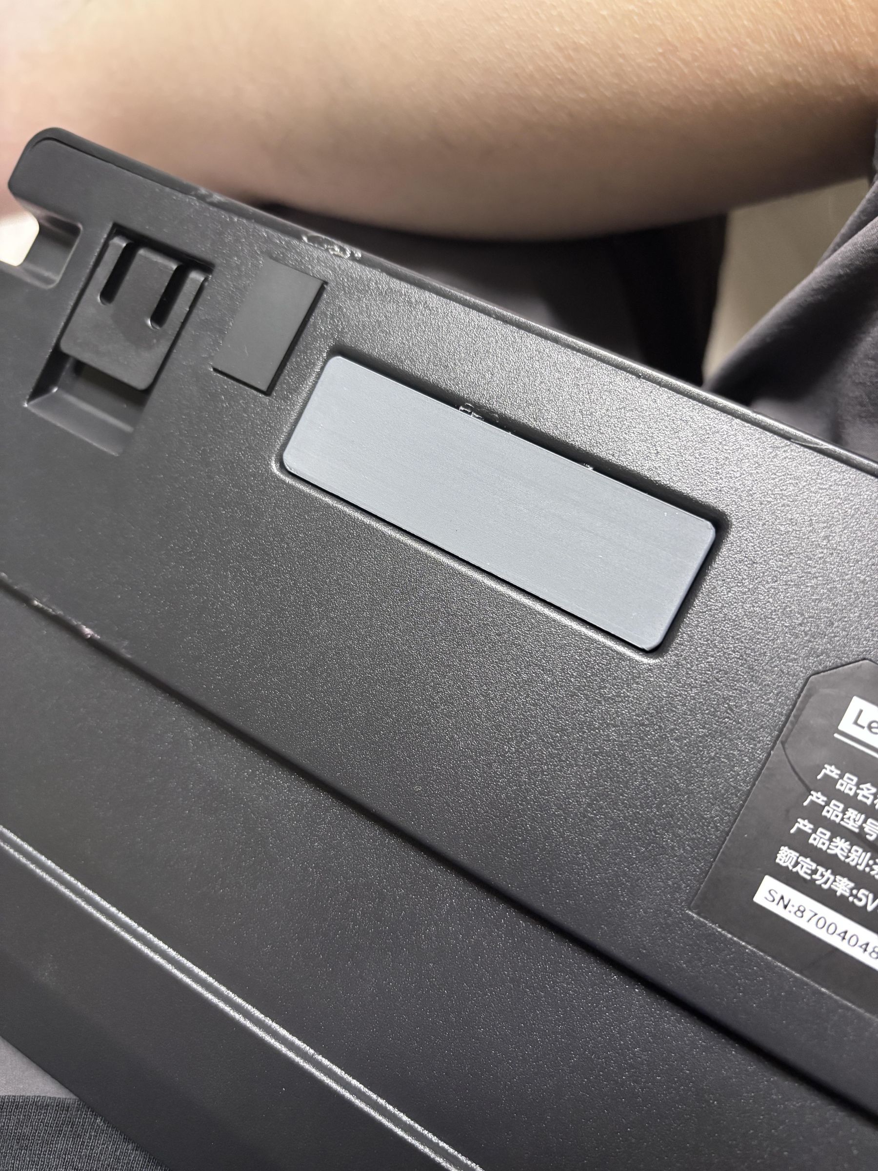
- Capacitive Slider: Positioned inside both sides of the housing, this custom capacitive slider array allows for seamless horizontal and vertical scrolling just by gliding a finger over the plastic surface. This was the biggest motivation for the project and represents the exact type of UX I’ve always wanted to achieve.
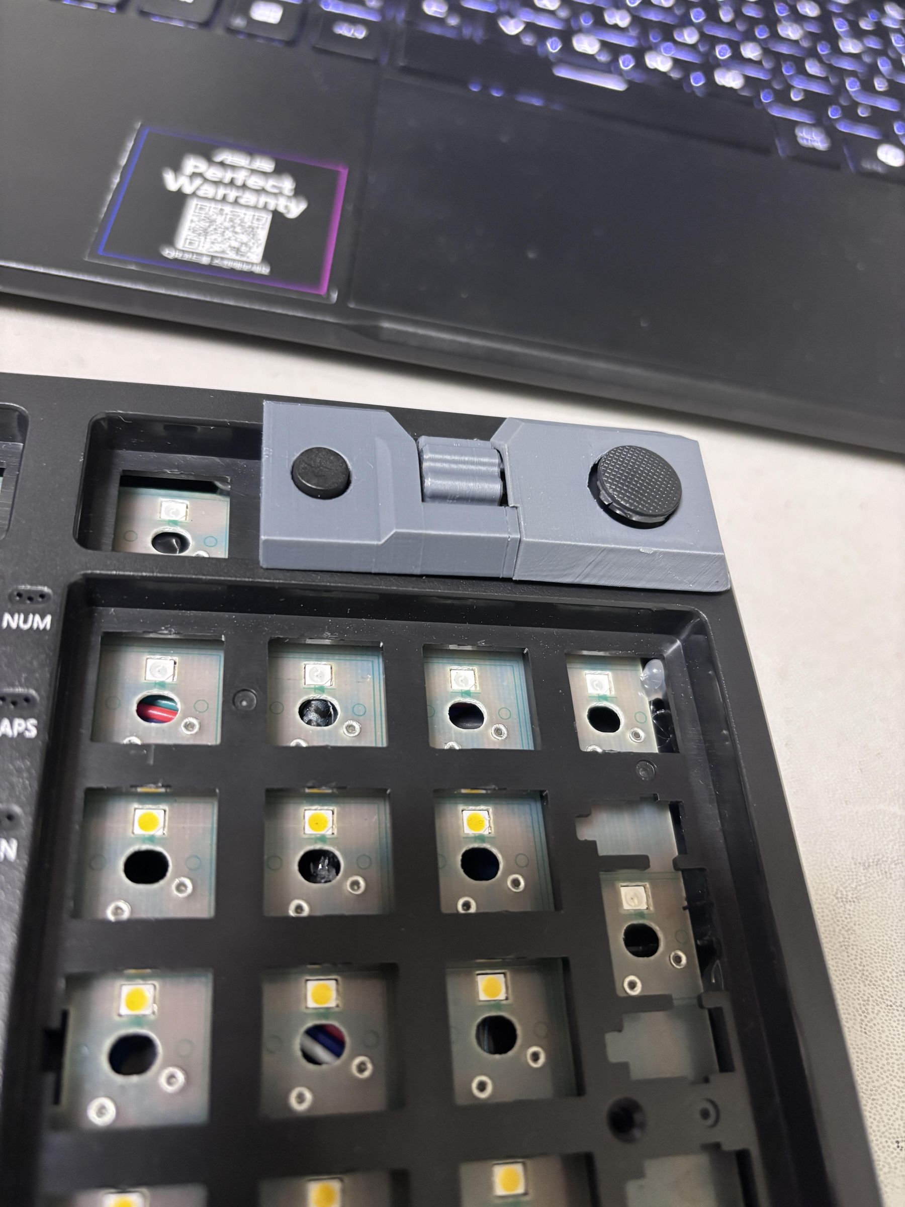
- Joystick & Scroll Wheel: Located on the top right, this tactile cluster—consisting of tactile switches, a scroll wheel, and a joystick—allows you to control horizontal/vertical scrolling, arrow keys, and the mouse pointer depending on the input mode. An indicator LED flashes to signal mode transitions.
- Simple Assembly Mechanism: Due to 3D printer build volume limits and ease of assembly, the enclosure had to be split into multiple parts. Rather than trying to hide the seams, I wanted them to become a deliberate design element. Instead of relying heavily on screws or glue, I used a press-fit system with tabs and grooves. While it might not be a robust engineering solution, it allowed the top plate to slide right in, creating a clean, minimalist exterior.
- Design: I drew heavy inspiration from minimalist design when shaping the layout. The top-right protrusion housing the joystick, was inspired by the mech designs of the Votann—a faction from Warhammer 40k. I used PLA-CF (Carbon Fiber) and the layer lines became an intentional texture, giving it a subtle, leather-or-stone-like feel.
Supplies
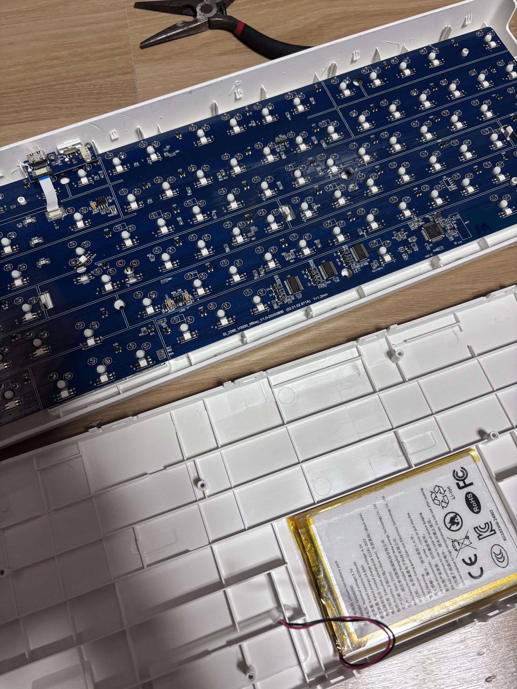
- Keyboard: Lenovo Aurora GK10 98-key
- Enclosure: 3D printed & laser cutted components
- Arduino Leonardo ETH
- MPR121
- Adafruit CH344F 2-port
- Thumbstick & button
- rotary encoder: Pololu Magnetic Encoder Pair Kit with Side-Entry
- wires & cable
- bearing & shaft
- custom PCB
Enclosure Design
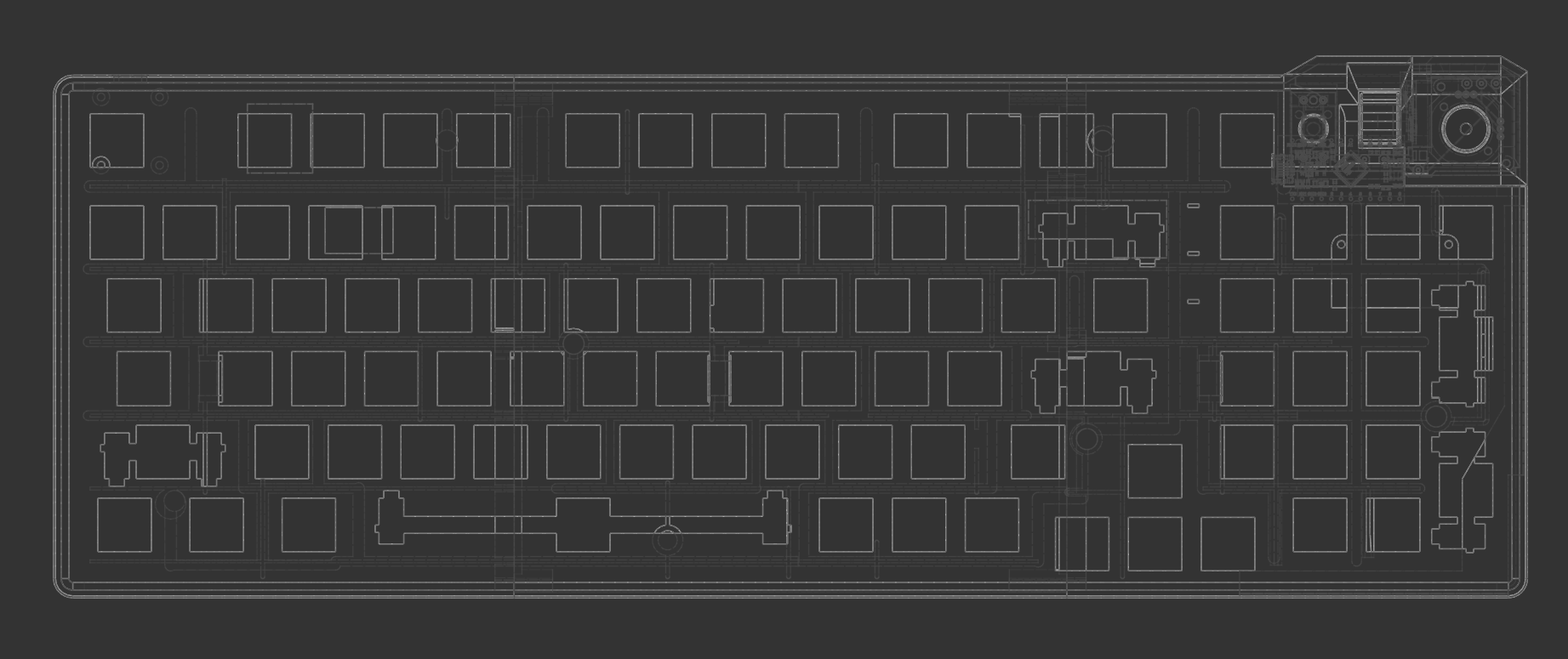
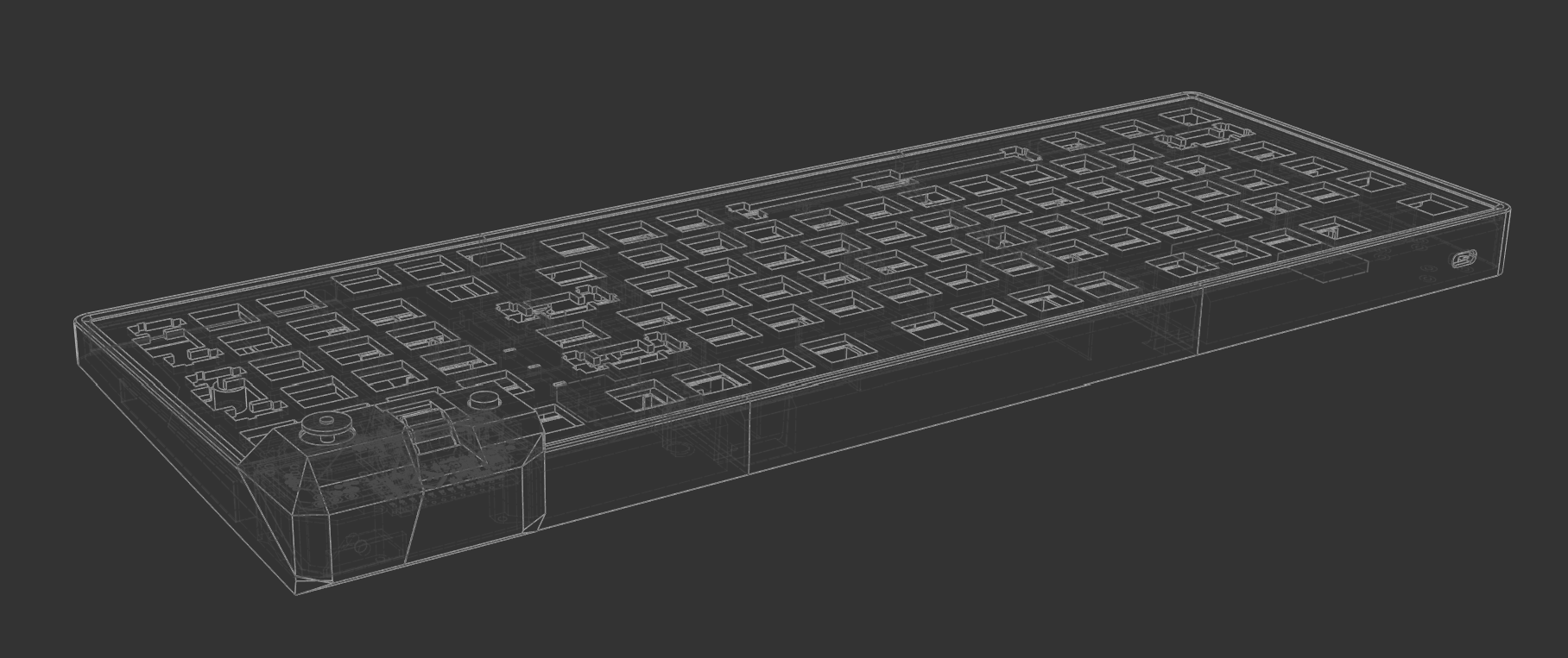
I started by designing the enclosure around the original Lenovo GK10 PCB.
Since I was adding quite a few things that were never supposed to be inside this keyboard—a microcontroller, USB hub, capacitive touch controller, joystick, and scroll wheel—the original housing wasn't going to work.
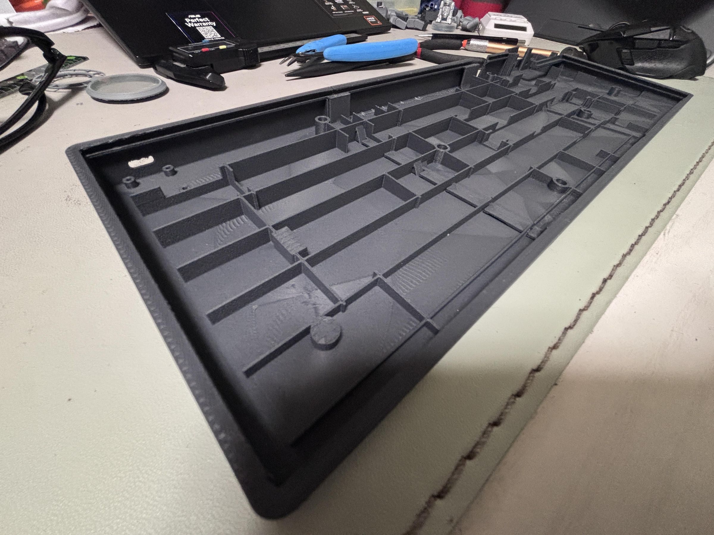
The enclosure was too large for my printer, so I split it into three sections.
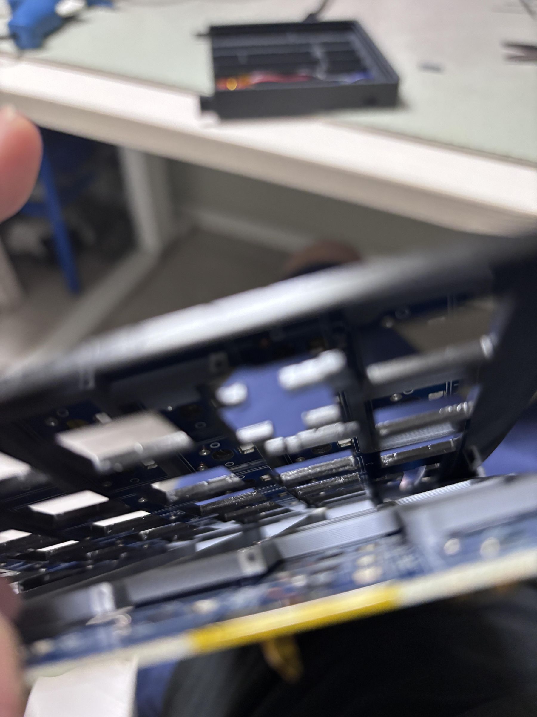
The top plate is a separate 2 mm acrylic sheet. Each of the three side enclosure pieces has a slot along its inner face, so the top plate is inserted horizontally into these slots as the enclosure is assembled.
This allowed me to keep the exterior clean without using many screws or glue. It worked, but there was one major downside: because the plate is trapped between the side pieces, accessing the internals later requires partially disassembling the enclosure. More on that later.
Drawing PCB Schematic
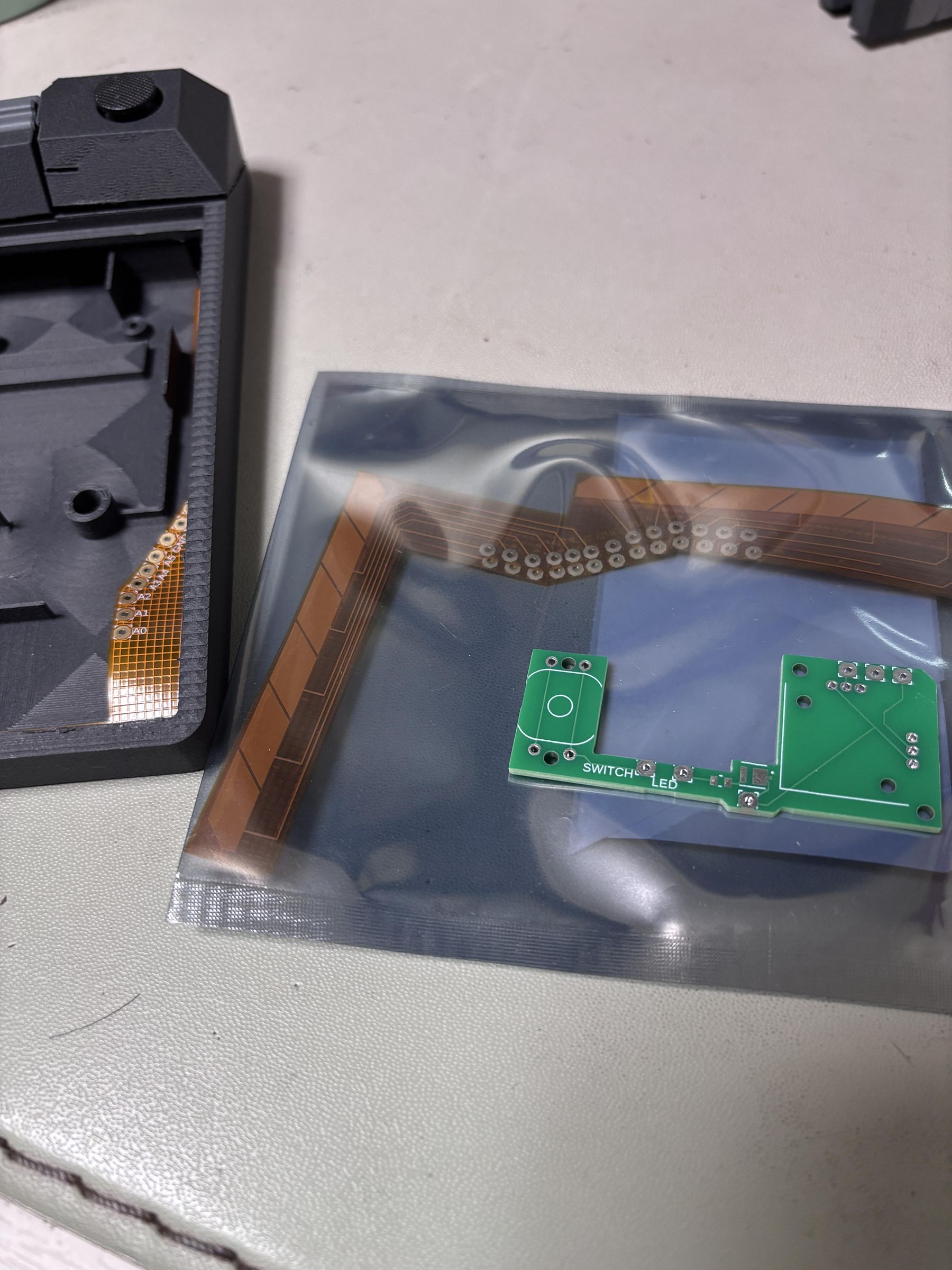
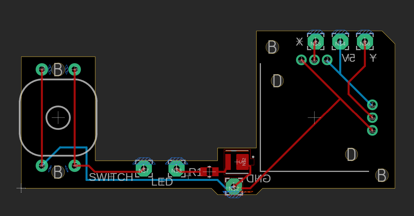
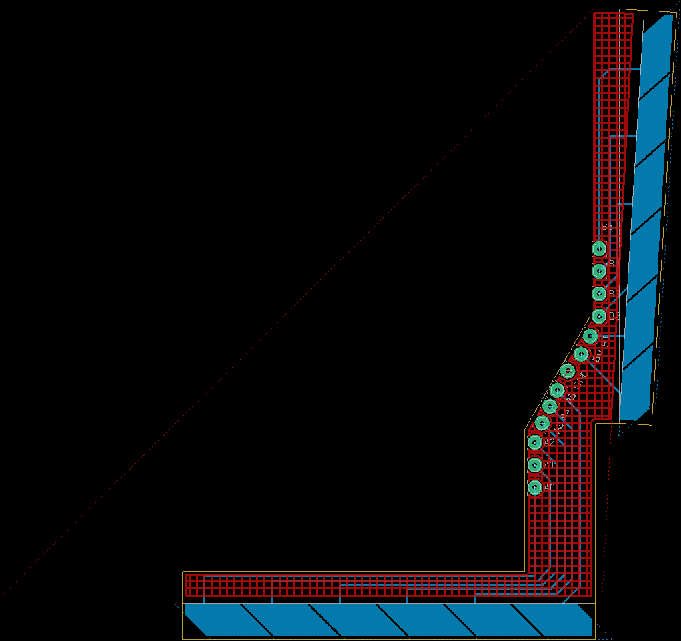
The capacitive sliders use an MPR121 capacitive touch controller.
I designed a custom FPCB with multiple electrodes so that it could sit directly behind the outer wall of the keyboard. The idea was to make the plastic surface itself behave like a touch-sensitive scroll area, without having any visible sensor on the outside.
The MPR121 handles the capacitive electrodes, while the joystick, scroll wheel, button, and indicator LED are connected to an Arduino Leonardo.
I used the Leonardo mainly because it can act as a USB HID device directly, which made it easy to turn all of these inputs into mouse, keyboard, and scrolling commands.
3D Printing & Laser Cutting
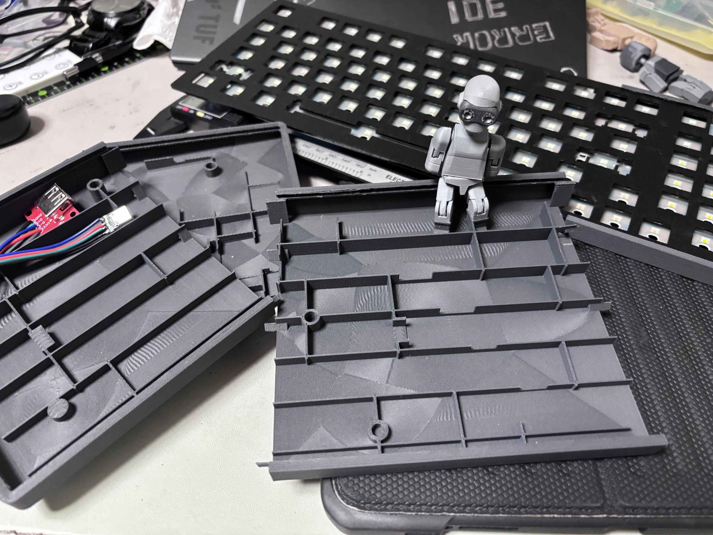
With the design finished, I printed the enclosure parts in PLA-CF using a Bambu Lab P1S, and laser-cut the 2 mm acrylic top plate using a Trotec laser cutter.
After printing, I test-fitted the enclosure sections, acrylic plate, keyboard PCB, and the components for the control panel before moving on to the electronics.
Since several PCBs and cables share a relatively limited internal space, make sure to check the component and cable clearances before assembly.
Soldering
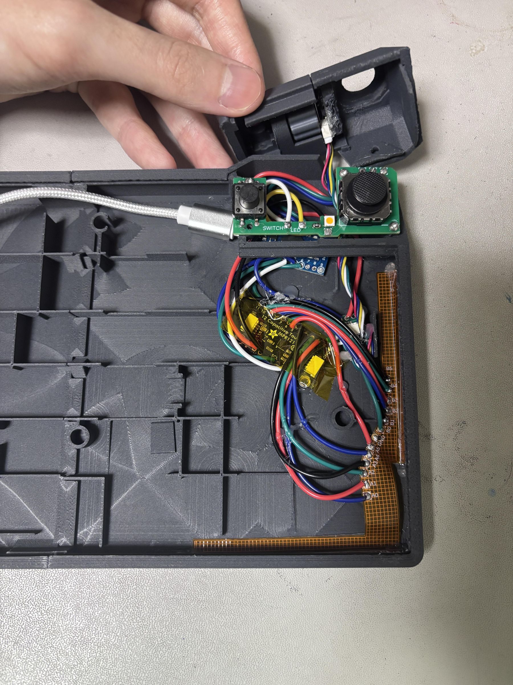
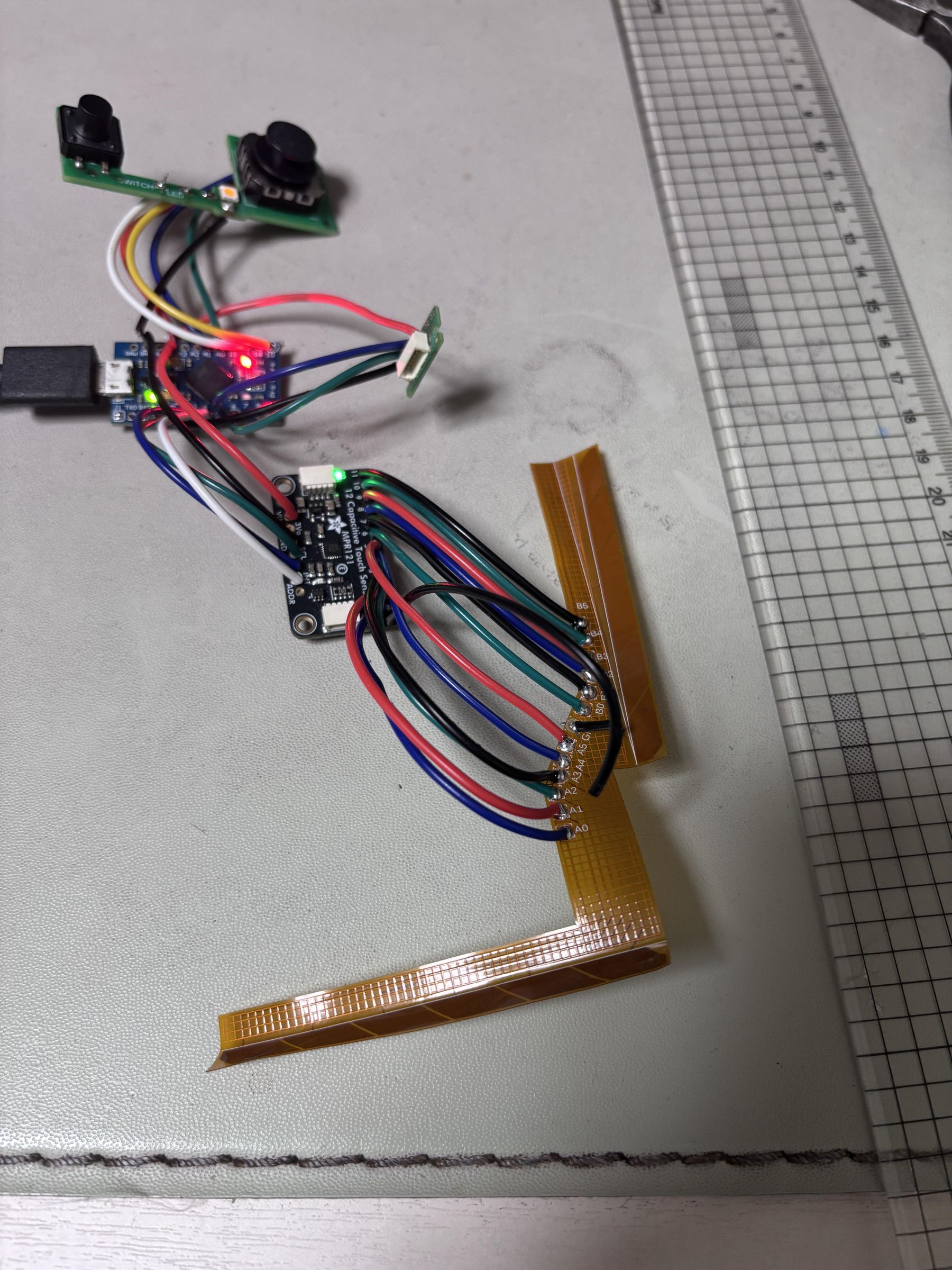
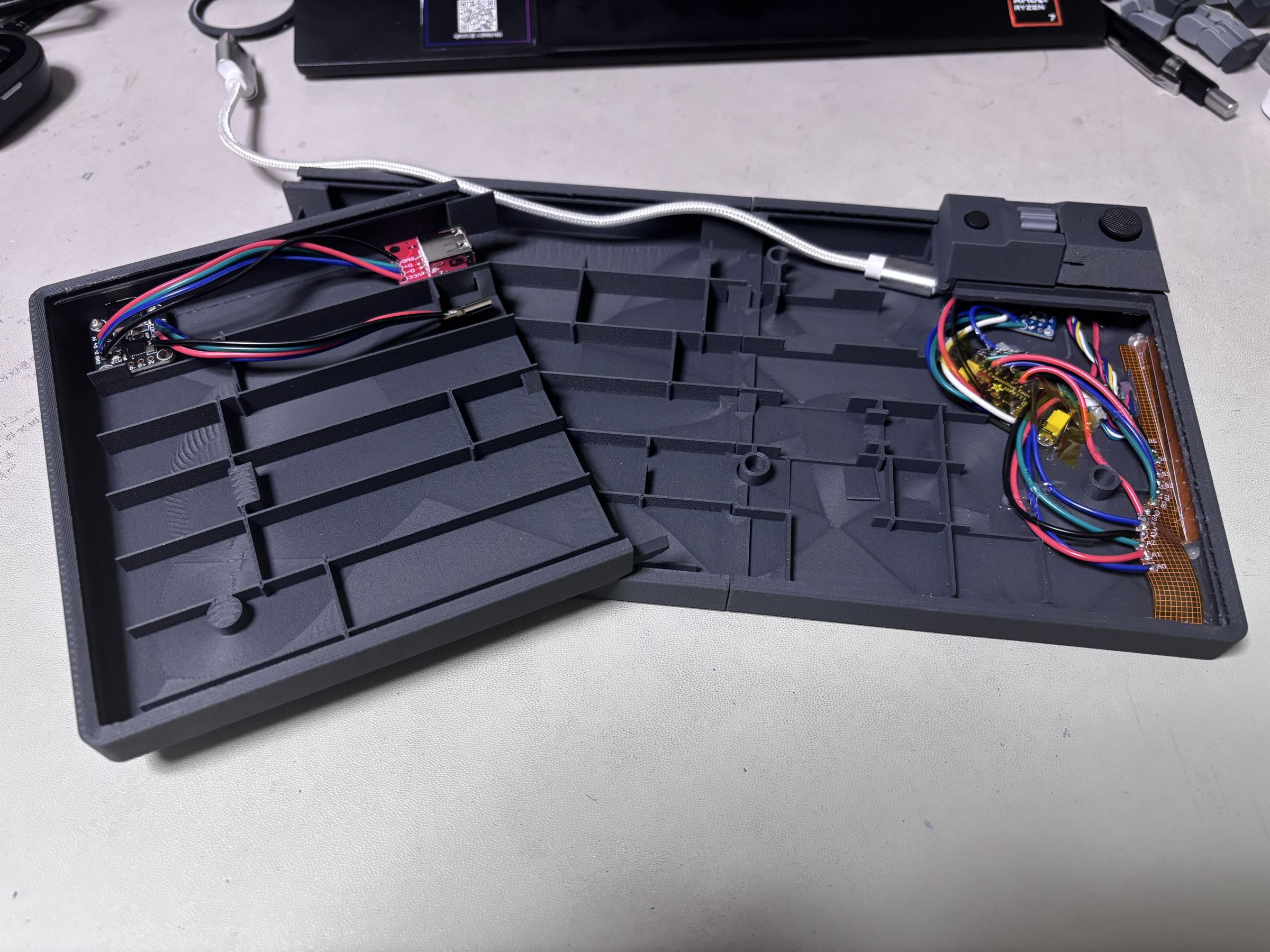
Next, solder the MPR121, thumbstick, magnetic encoder, mode button, and indicator LED to the Arduino Leonardo.
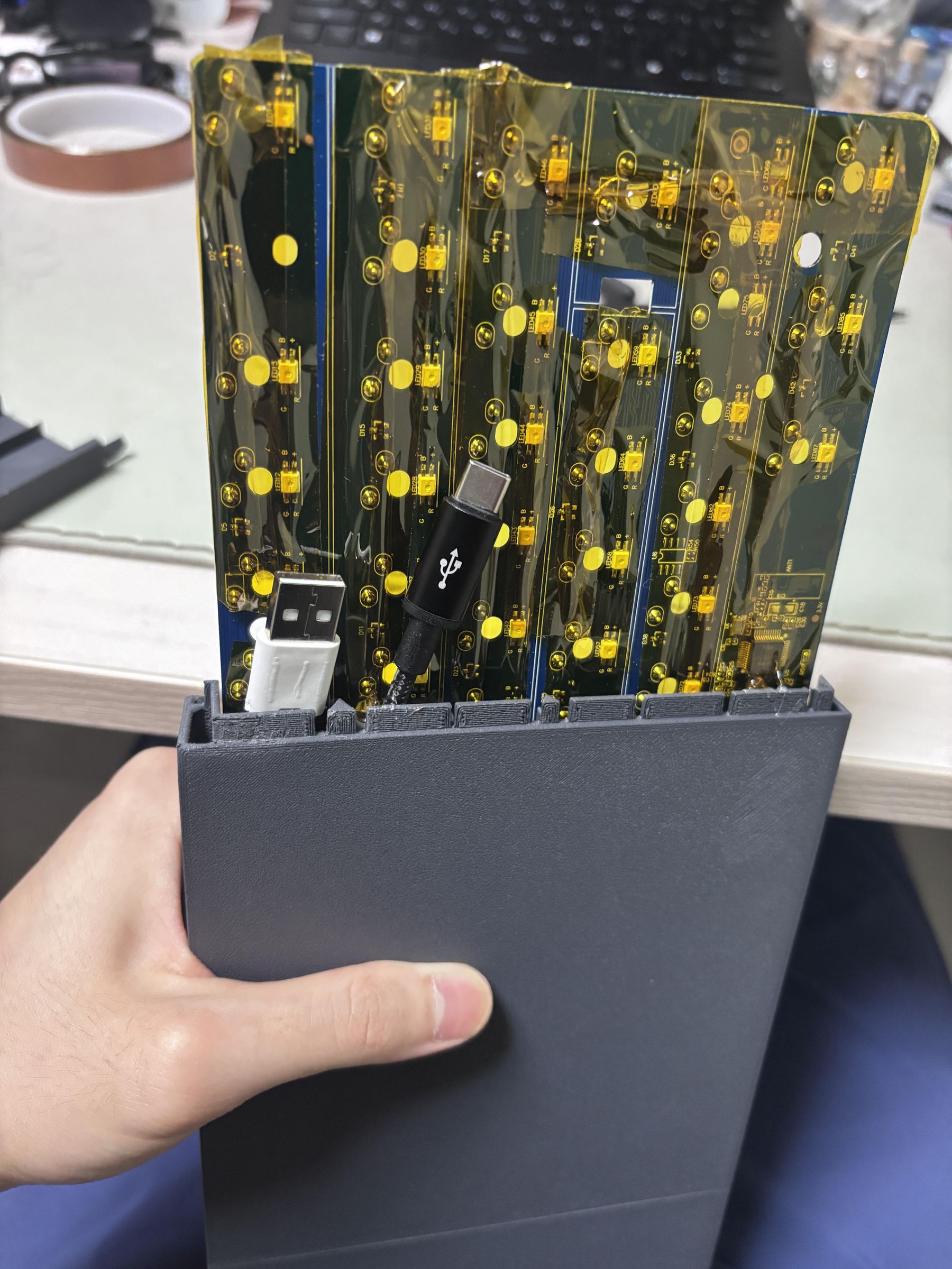
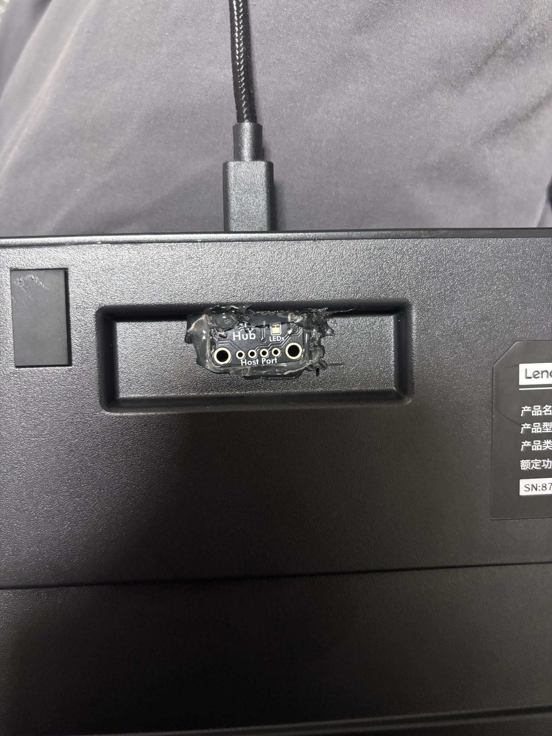
I used a small two-port USB hub to connect both the original keyboard PCB and the Leonardo through a single USB connection.
Connect the custom FPCB to the MPR121, then test each input individually before installing everything into the enclosure. Most of the solder joints become difficult to access after the final assembly.
Calibration
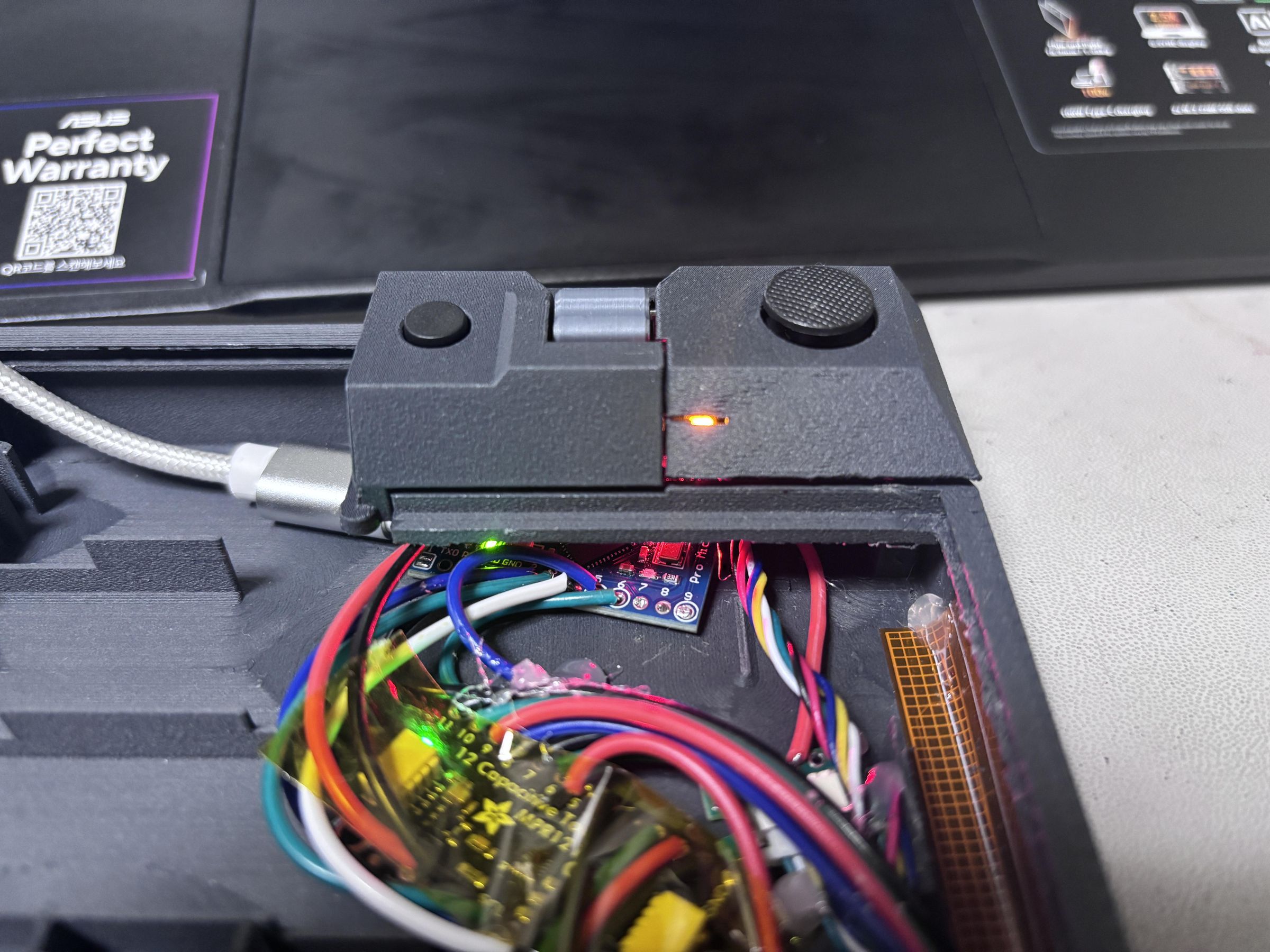
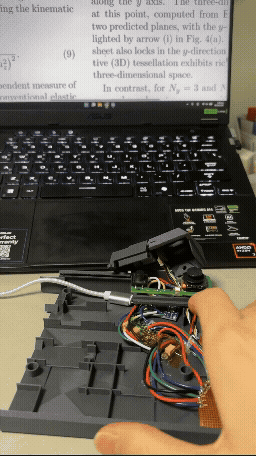
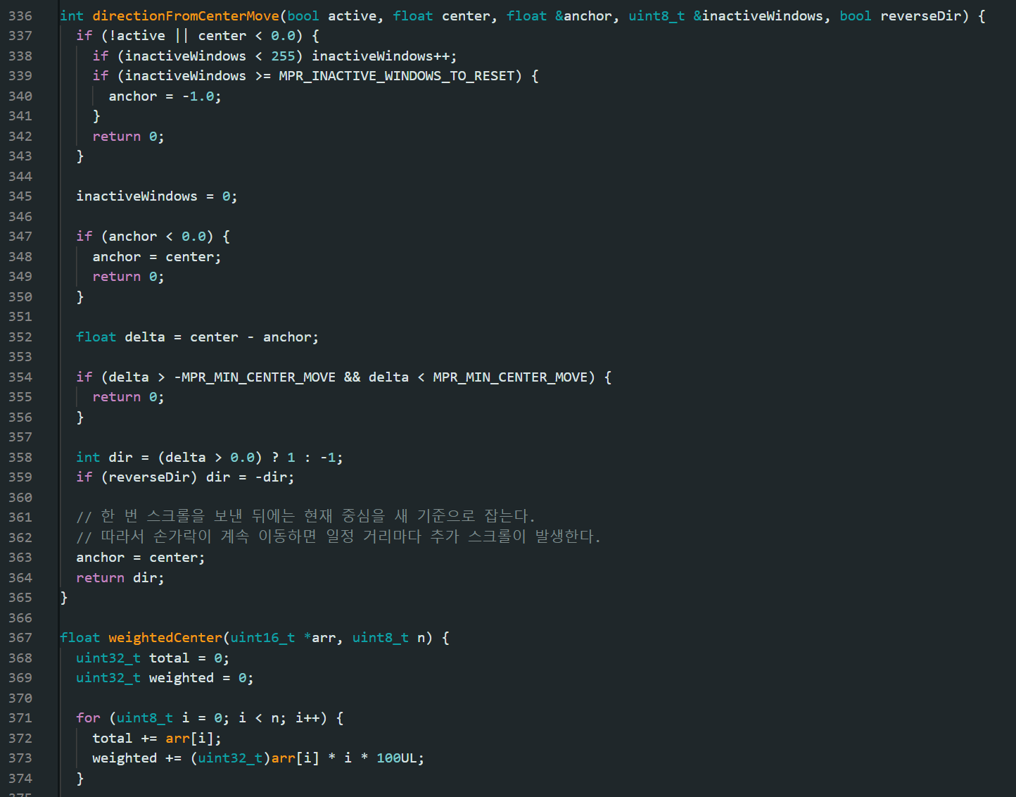
The capacitive slider required some calibration before it could be used reliably.
The electrodes are relatively small and sit behind approximately 1 mm of printed PLA, so the capacitance change caused by a finger was fairly small. Also, the baseline and sensitivity were not exactly the same for every electrode.
To account for this, I calibrated each electrode individually and assigned a different detection threshold to each one. Each electrode is treated as a discrete input based on its own threshold rather than using a single global threshold for the entire array.
Using only these discrete inputs would make the slider behave like a row of touch buttons, so I used a center-of-mass calculation across the detected electrodes to obtain a smoother position estimate.
The resulting position is then used for horizontal or vertical scrolling.
Panel Assembly
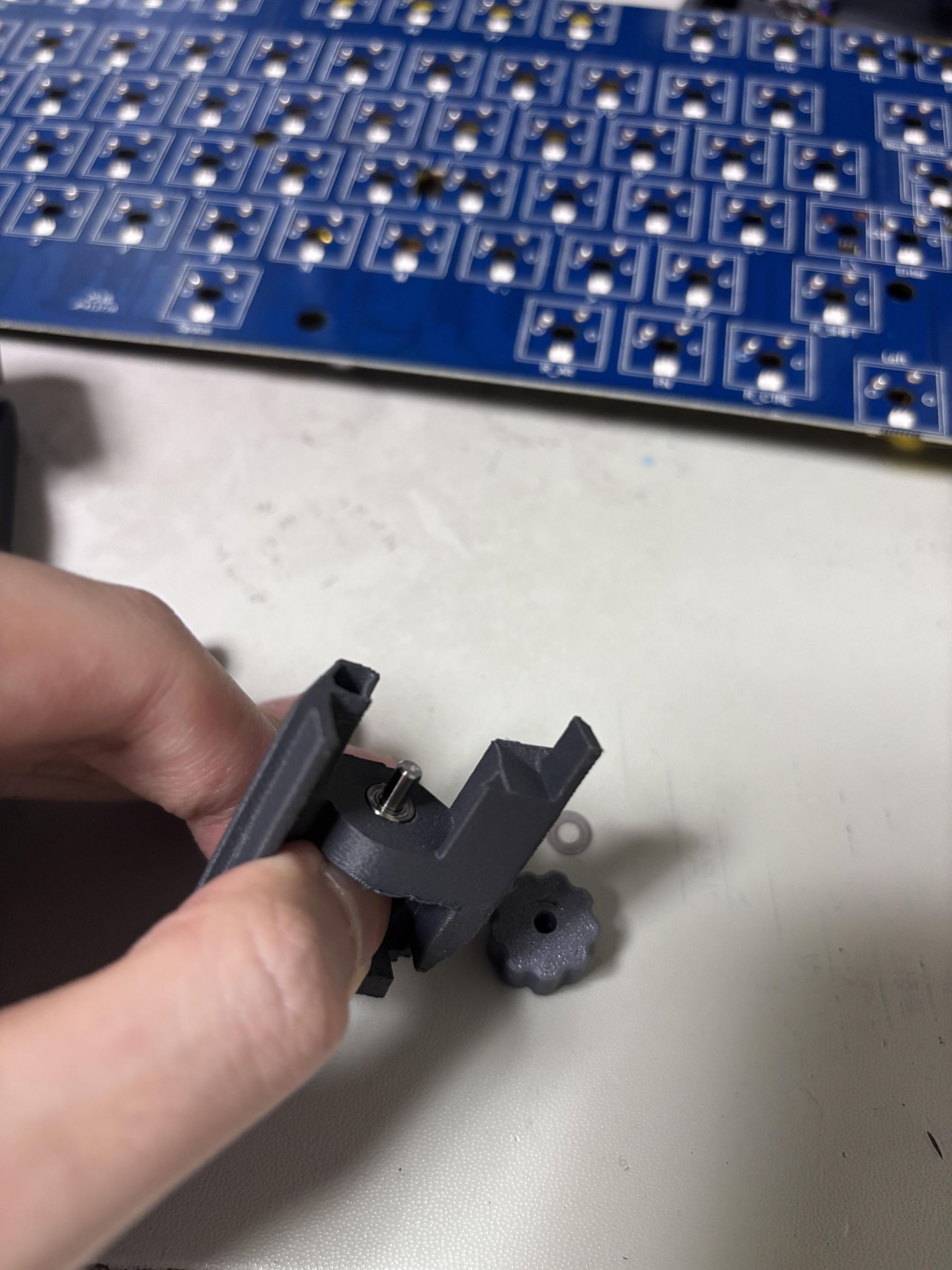
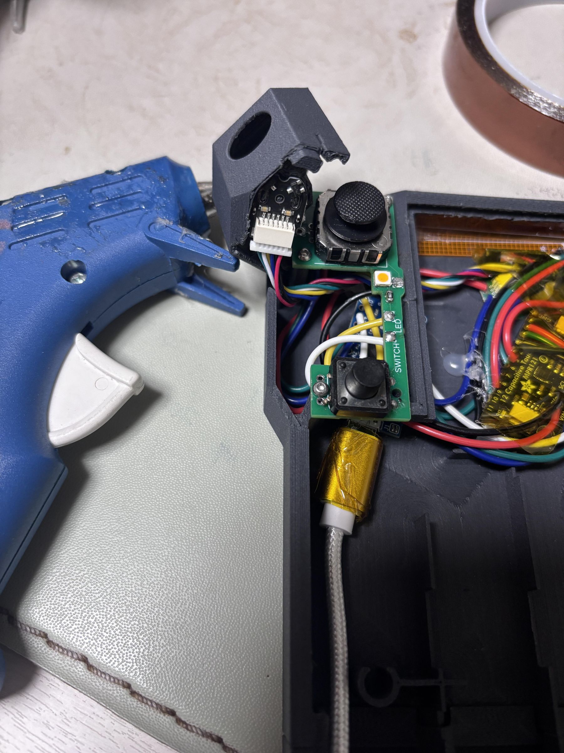
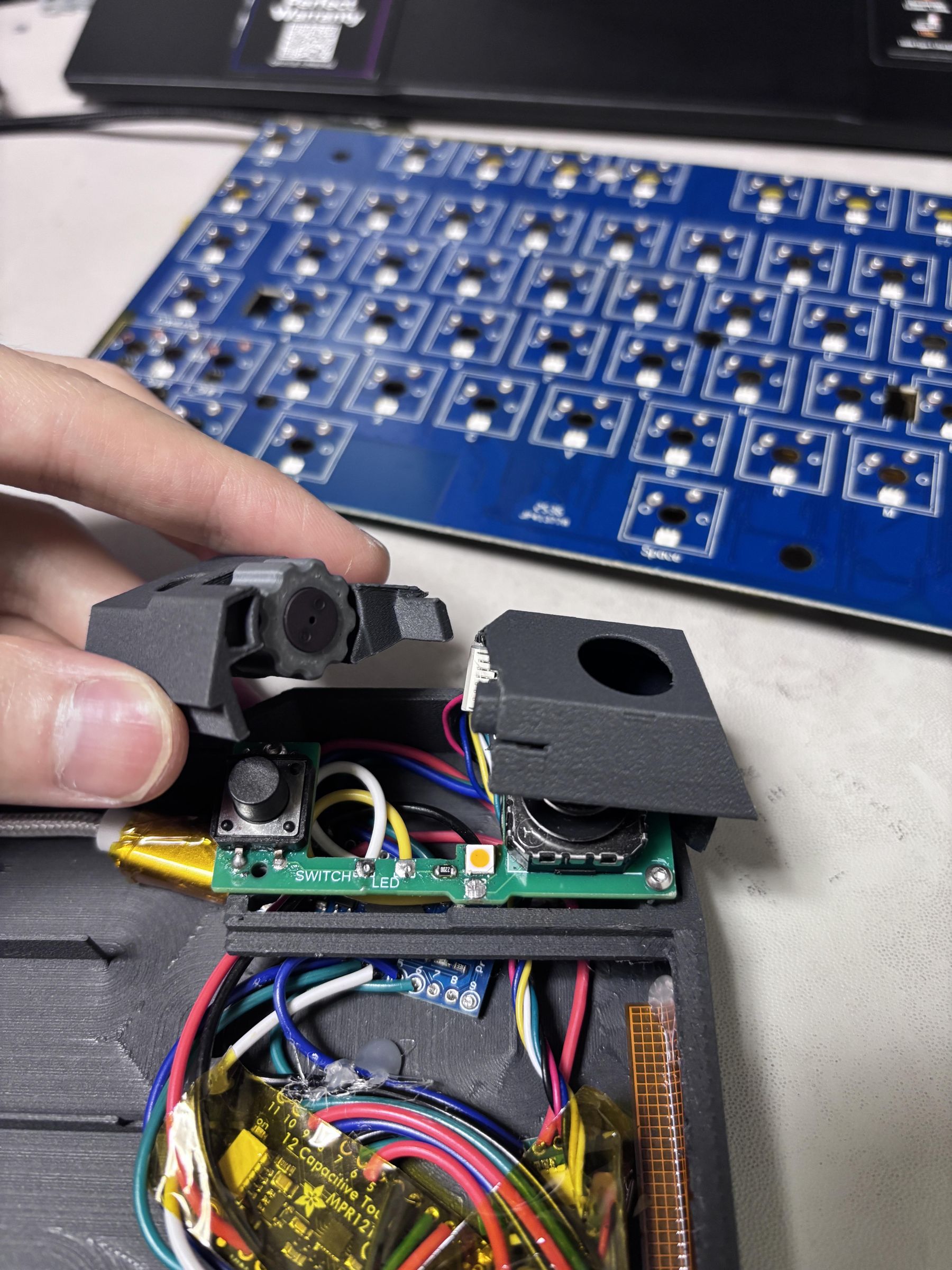
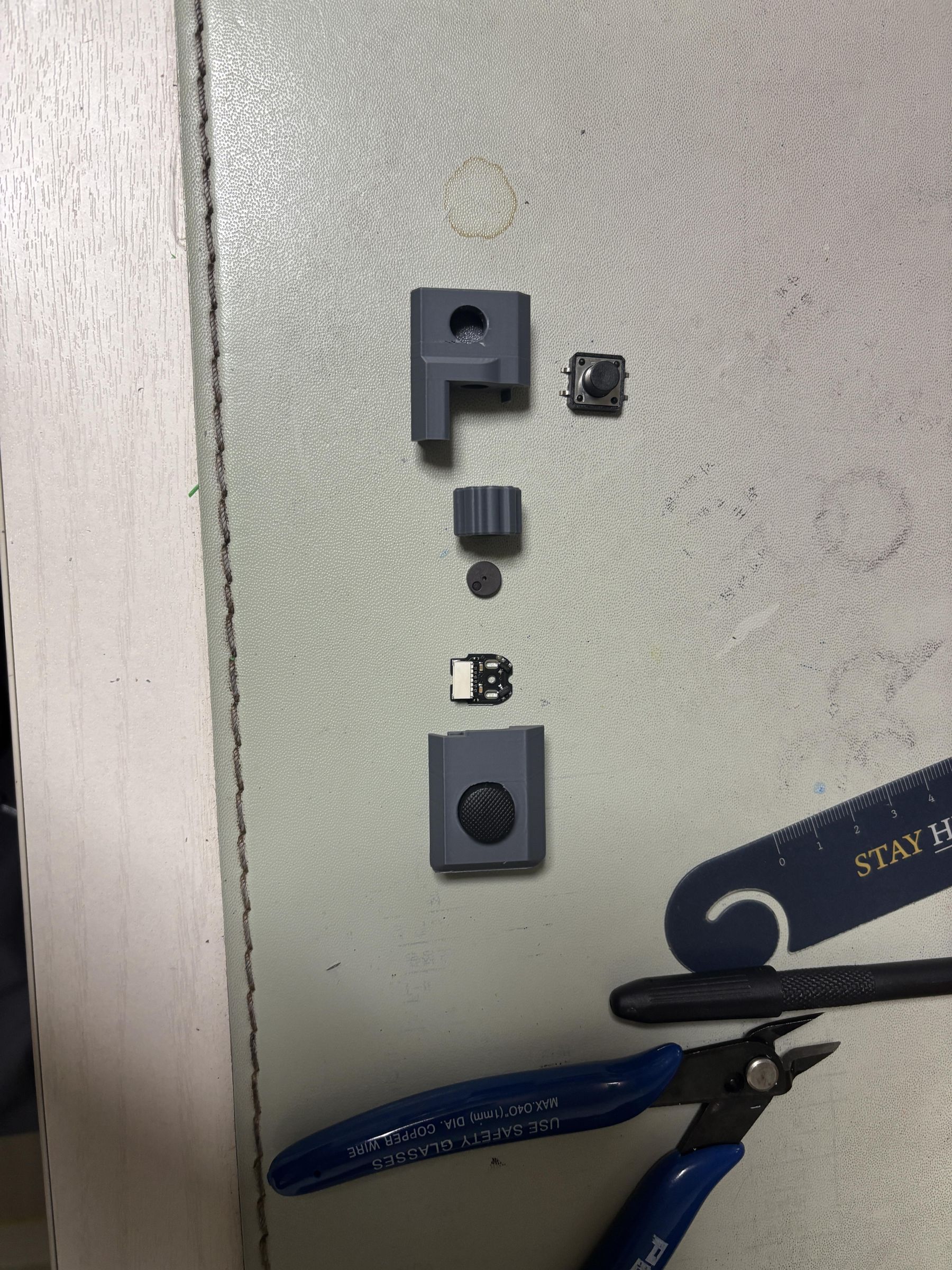
The top-right panel contains the joystick, scroll wheel, button, and indicator LED.
The scroll wheel is mounted on a 3 mm shaft supported by bearings, with a magnetic disc used for the encoder.
I first assembled the wheel, shaft, bearings, and encoder and checked that the wheel could rotate freely. The joystick, button, and LED were then installed into their respective positions in the panel.
Enclosure Assembly
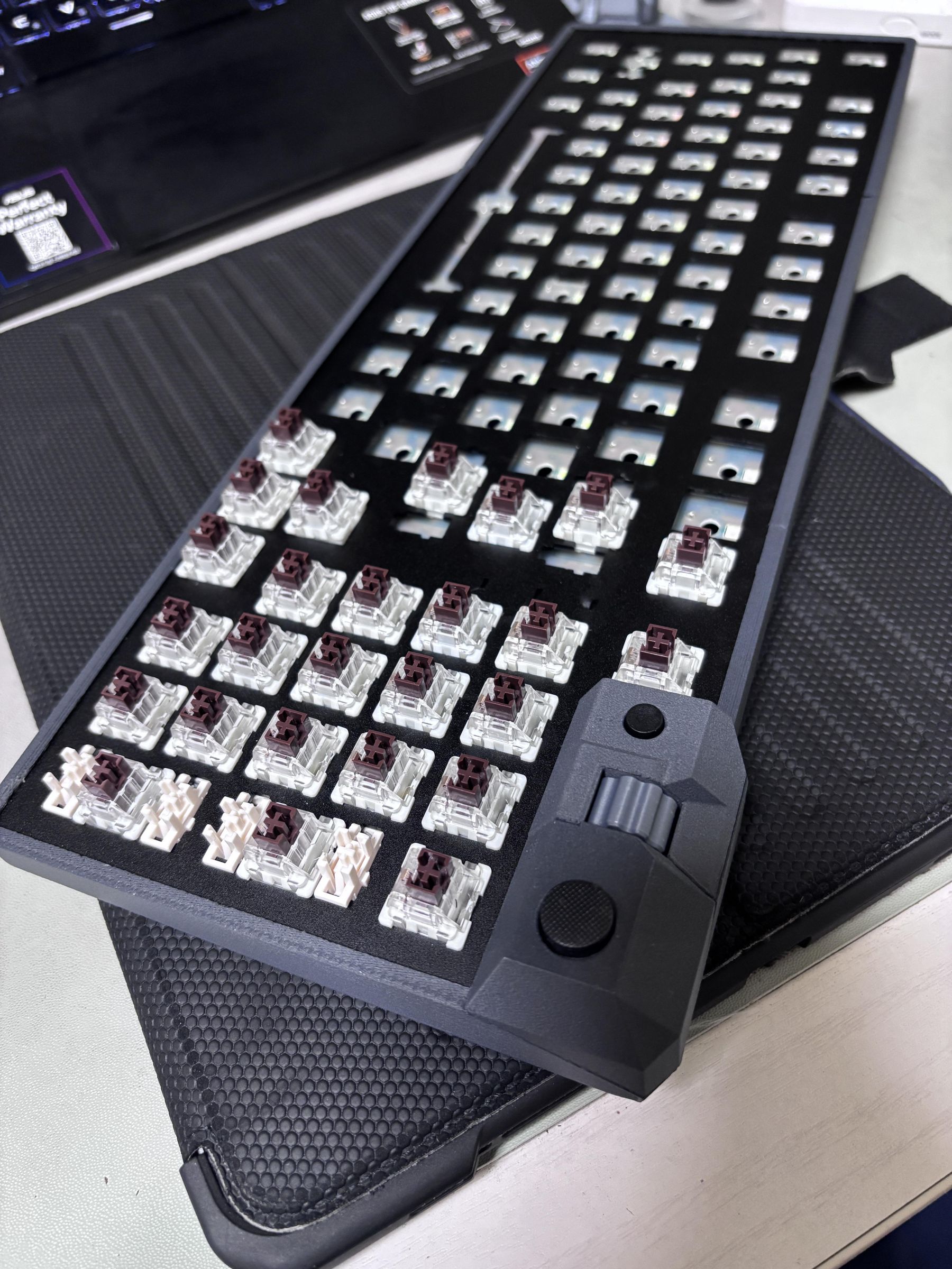
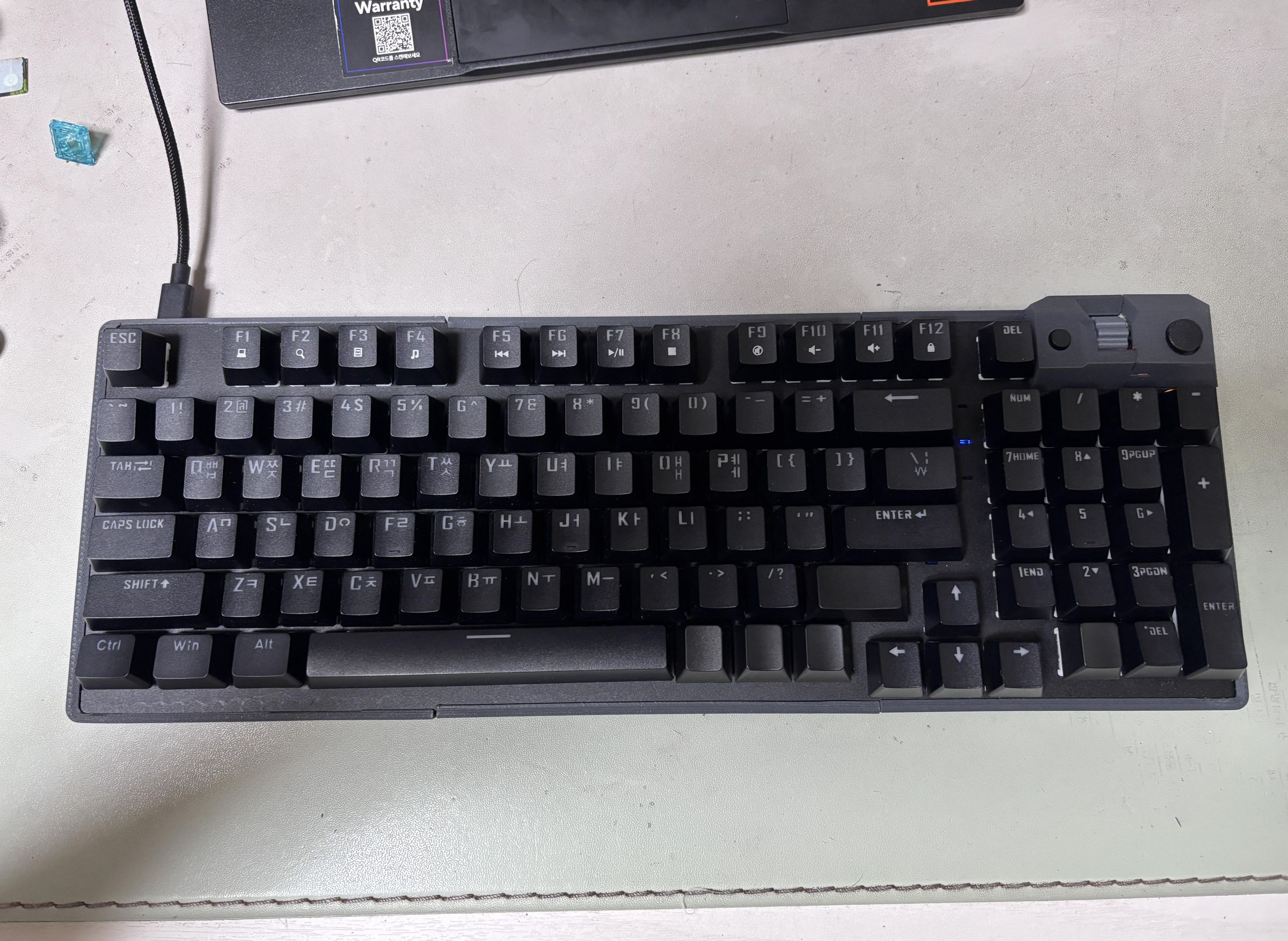
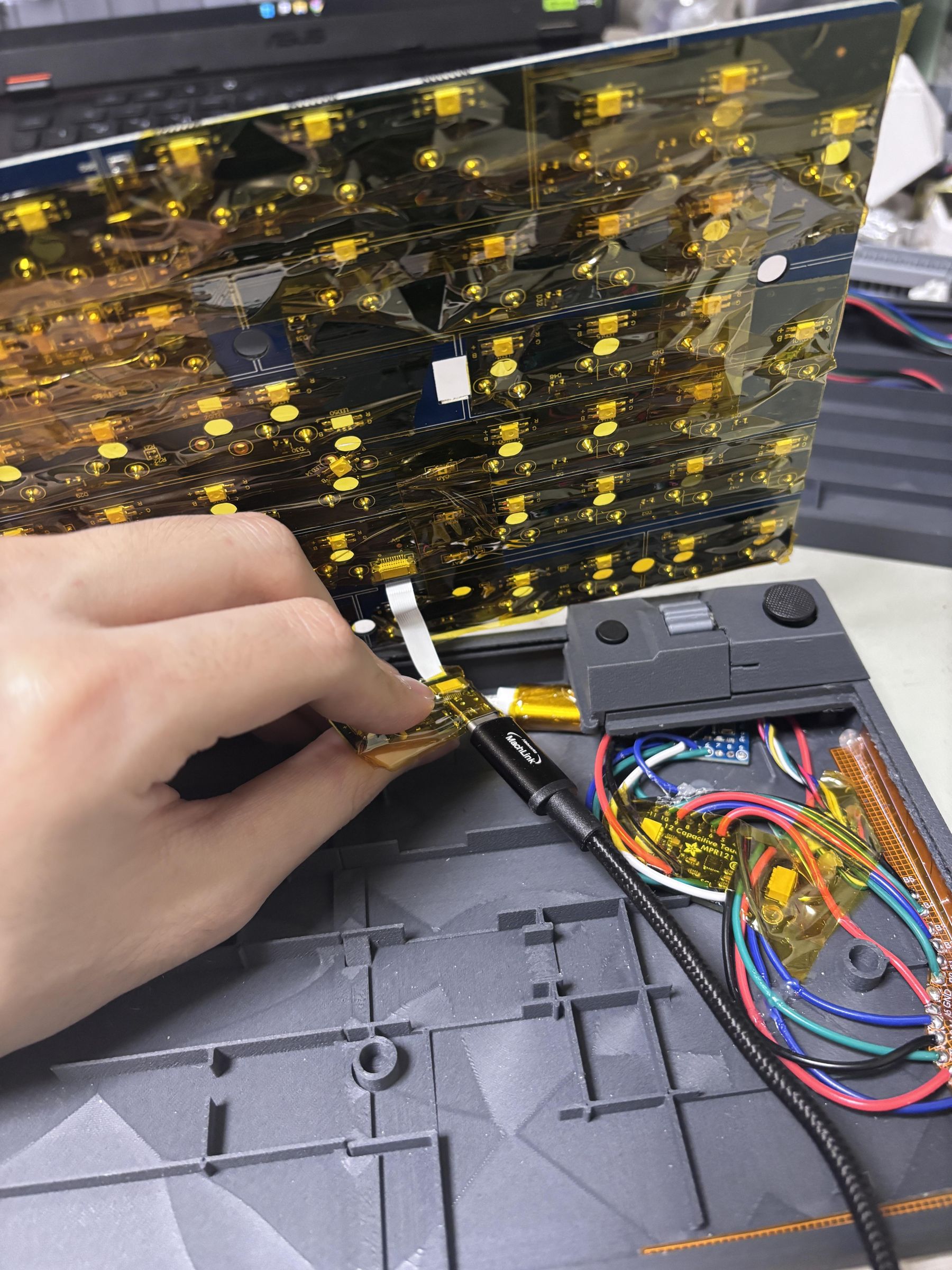
With all the individual parts ready, I installed the electronics and assembled the enclosure.
Since several PCBs and exposed solder joints are packed closely together, I insulated the boards to prevent accidental shorts between components.
After arranging the wiring and making sure nothing was being pinched or interfering with the moving parts, I carefully closed the enclosure and secured everything in place.
Finally, I connected the keyboard to the computer and tested all of the original keys and the added controls to make sure everything was working properly.
If You Happen to Build Something Like This...
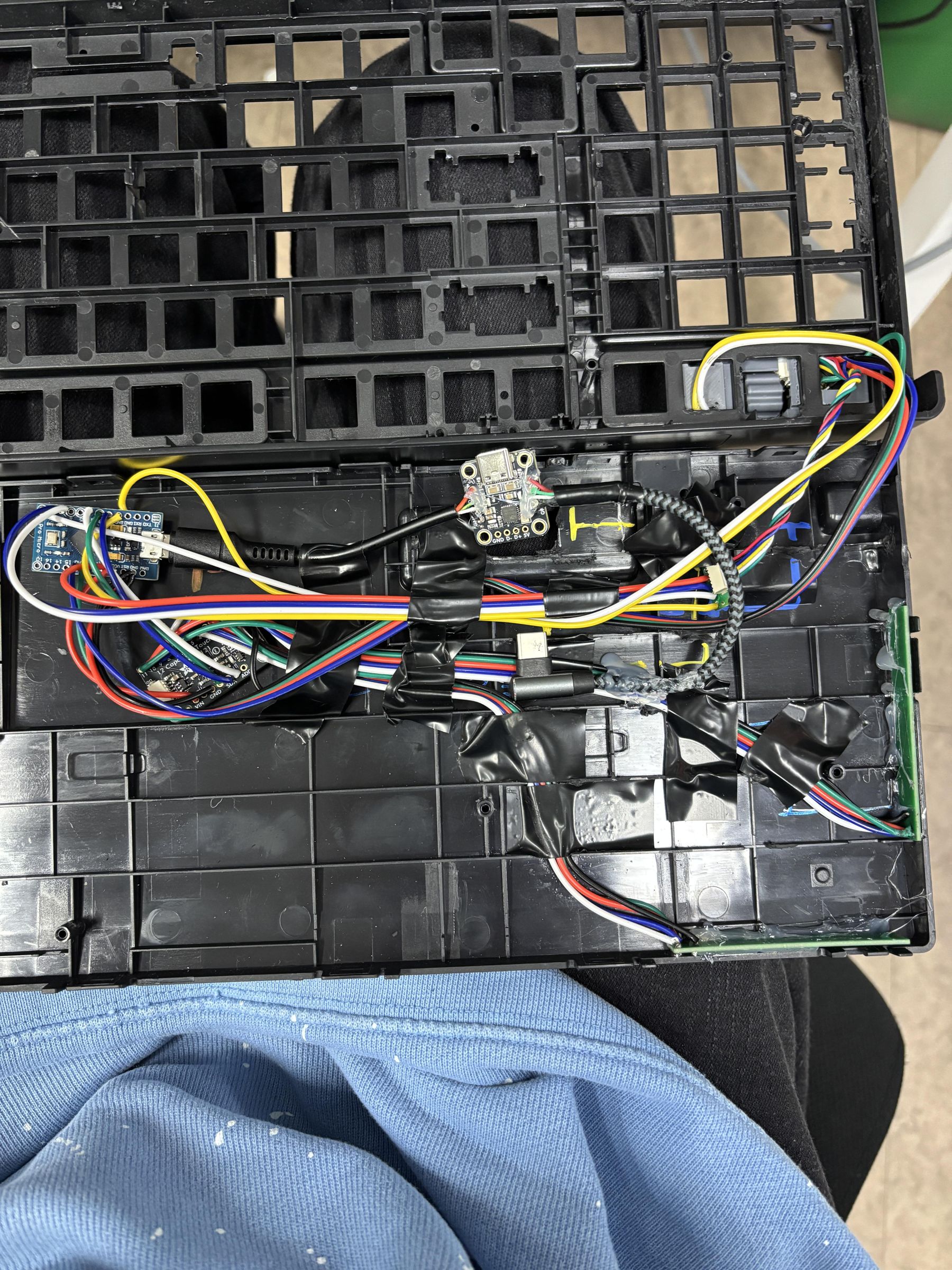
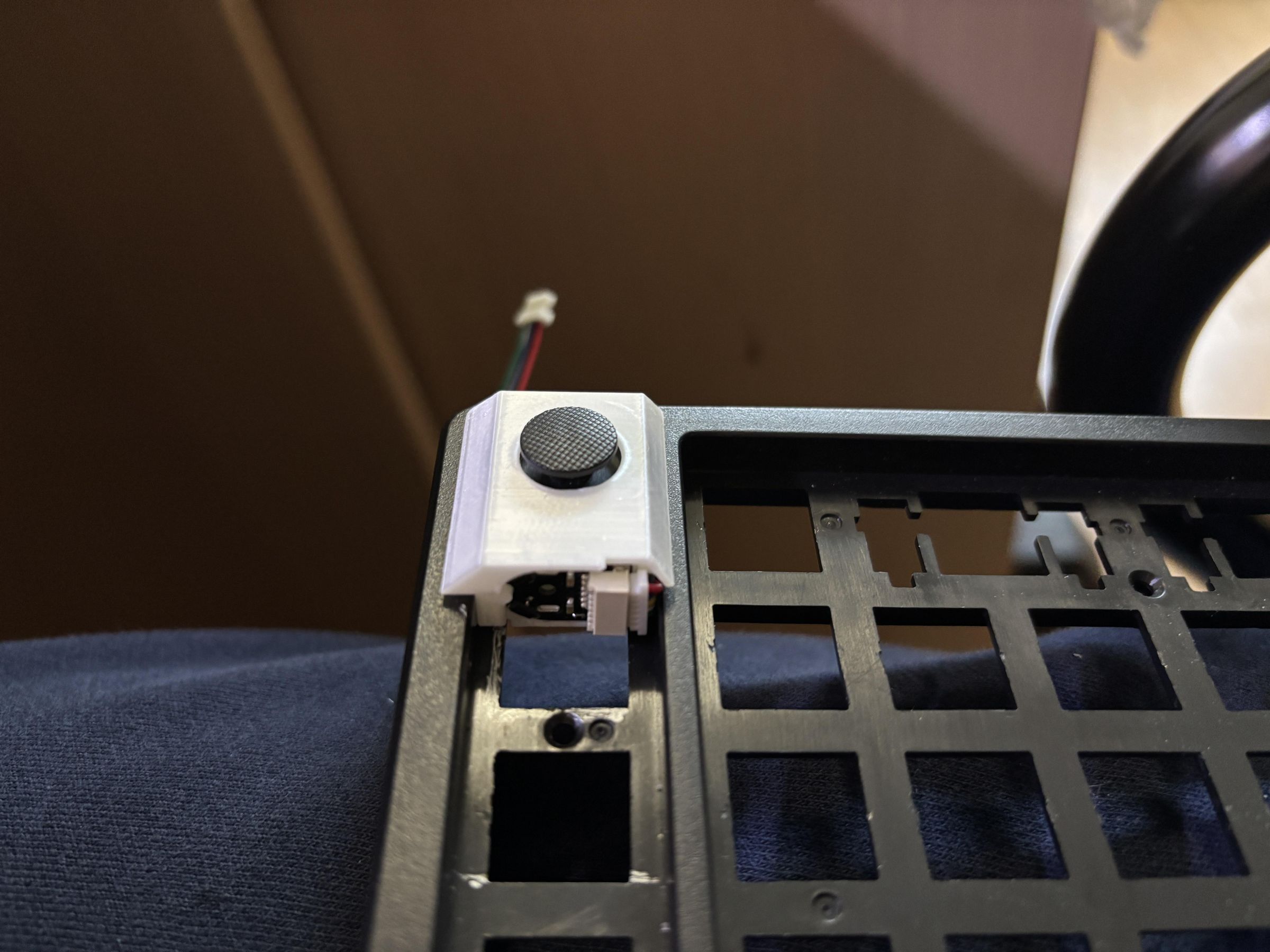
FPCB schematic and code is available here.
The mechanical design is not publicly available, and I don't currently plan to release it. While it worked for this build, I don't consider the design robust or assembly-friendly enough to recommend for reproduction.
Godspeed on your journey...!
P.S. If possible, avoid designing the enclosure to assemble horizontally. It makes later repairs much more difficult.
Also, try not to pack multiple PCBs into a limited space. Hand-soldered components and wires pressing against each other can eventually make the system less reliable.