Tim's DFPlayer Plus


![Tim's DFPlayer Plus [I got the PCB]](/proxy/?url=https://content.instructables.com/F18/5K7L/M59MFOQL/F185K7LM59MFOQL.jpg&filename=Tim's DFPlayer Plus [I got the PCB])
This project was inspired by one of my favourite YouTube channels.
- I mention them in my first video for this project where I was prototyping the project Tim's DFPlayer Plus [Talking about it]
- The video above is me showing the completed version on the PCB I got from

is a great place to get you prototyping PCB's at a very low price, if it wasn't for I would not be able to do projects like this.
- For people who want to make this project also make it very easy for you to do that.
- They have a web site where people can share the projects, so people can order them at a click of a button.
- Depending on how much work you want to do your selves, you can order just the PCB or have it populated.

What does it do?
This board is based around the DFPlayer Mini Module.
This bord can be used in two ways:
- As an MP3 Player. You can attach speakers and play your music using the two amplifiers.
- Use it as a tool when diagnosing amplifiers. It will play samples and give a synchronized pulse, to which you can attach your oscilloscope.
The DFPlayer Module only has a mono Amplifier for one speaker.
- There is a mod to do to the DFPlayer module, so that an extra amplifier can be used to give you amplified stereo to two speakers.
Additions to the DFPlayer Module.
- Another Amplifier to give amplified stereo.
- An Encoder switch to select MP3 File Number and set Volume.
- An OLED to display MP3 File Number or volume.
- 3mm Audio jacks for easy connection of devices.
- Pins for using a 5 volt battery.
- USB Mini socket for powering from USB.
- Buttons for various functions.
Supplies

.png)


There is a Bill Of Materials (BOM) produced from the circuit diagram.
Here I have shown the major components.
One PCB, I have done a shared Project at Just click the link.
- When you order a PCB from you are able to choose just the PCB, or have some or all the components fitted.
One DFPlayer Mini
- There are some bad versions of this be aware of what you find.
One OLED
- This is an 0.96" SSD1306 128x64 I2C module.
- Looking om top of the header pins. the sequence should go GND, VCC, SCL, SDA.
One Rotary Encoder
- This is an encoder with a push button, it has 5 pins.
- I have used a 15mm long shaft with the star serrations.
One STM8S103F3P6
- Make sure it is the "F3" 8k flash, I have used all available flash.
One LM4871 Amplifier.
- I have specified the LM4871, because that is what I have used and it works OK.
- I think the DFPlayer module uses an 8002. But I recommend stick with what I used because mine works.
One AMS1117-3.3
- I am running the system at 3.3 Volts.
Three 3mm Stereo Jacks
- I have attached a data sheet that shows the footprint of the one I have used.
Five Button
- 6mm x 6mm, 5mm High
One USB Mini Jack
- I have attached a data sheet for the type I have used.
There are some DuPont headers and pins.
- Note the ones I have for the horizontal pins are the ones that sit flat to the PCB. It should not matter if you use the other type.
All the SMD peripheral components are 2012 Metric, 0805 Imperial size.
- I don't go smaller than this, because I don't see well these days haha.
Tools
I have used an STM8S103F3P6 Microcontroller.
- This will require programming.
- To do the programming an ST-Link v2 is required.
- Also ST Visual Develop IDE from STMicroelectronics.
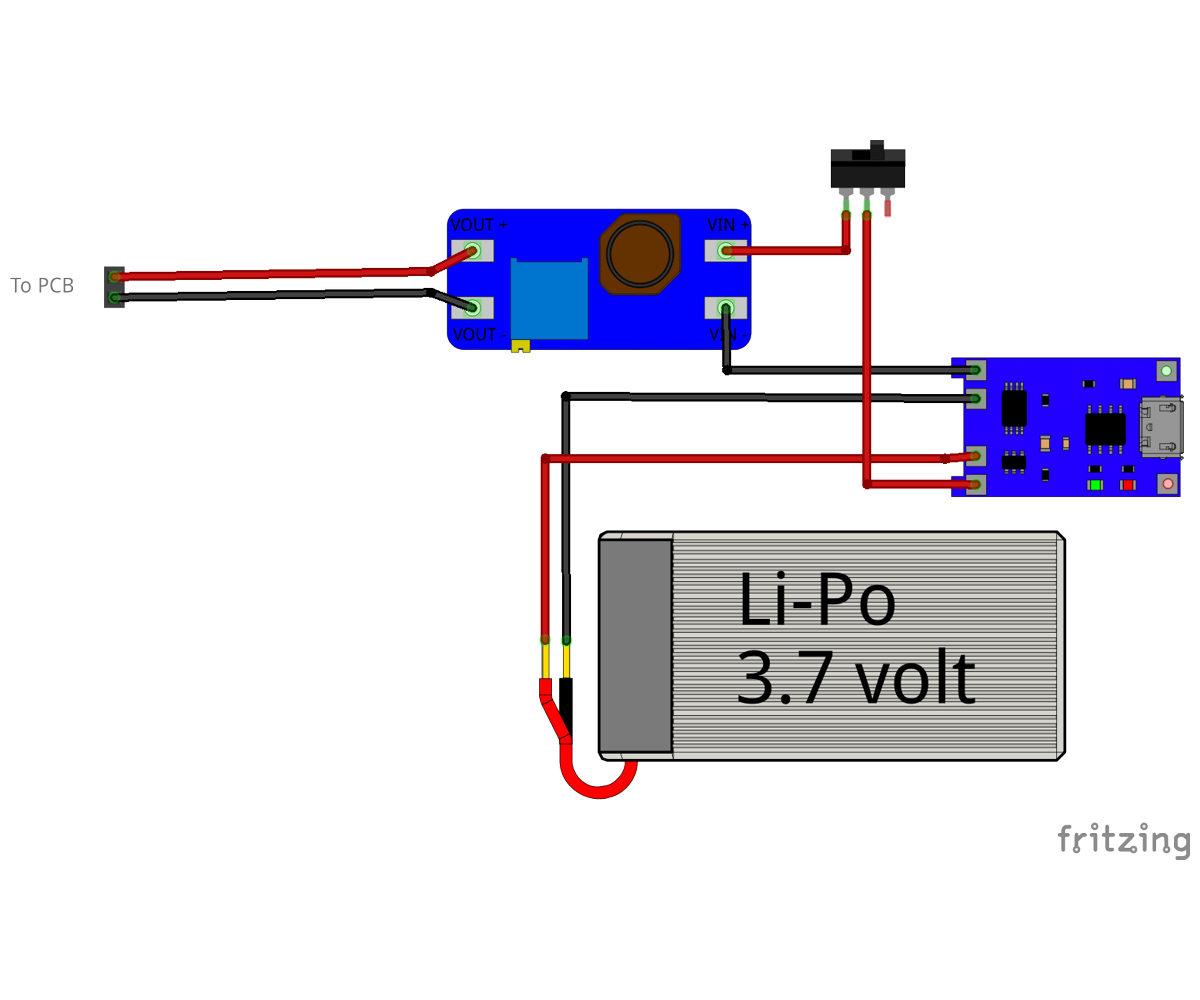
Battery Powered Mod
To make it battery powered you will need:
One Li-Po Battery.
- As shown in the image. (Take the size as max size that will fit in the box.)
One USB Battery charger.
- I have used the HW-107, It has the battery protection also.
One Boost.
- I have used an MT3608 based boost, I am boosting the battery voltage to simplify the use of multiple Power options.
One Switch.
- I have used a basic slide switch.
Some M1.7 Self taping screws.
- The majority are 6mm long, there is a couple 10mm long.
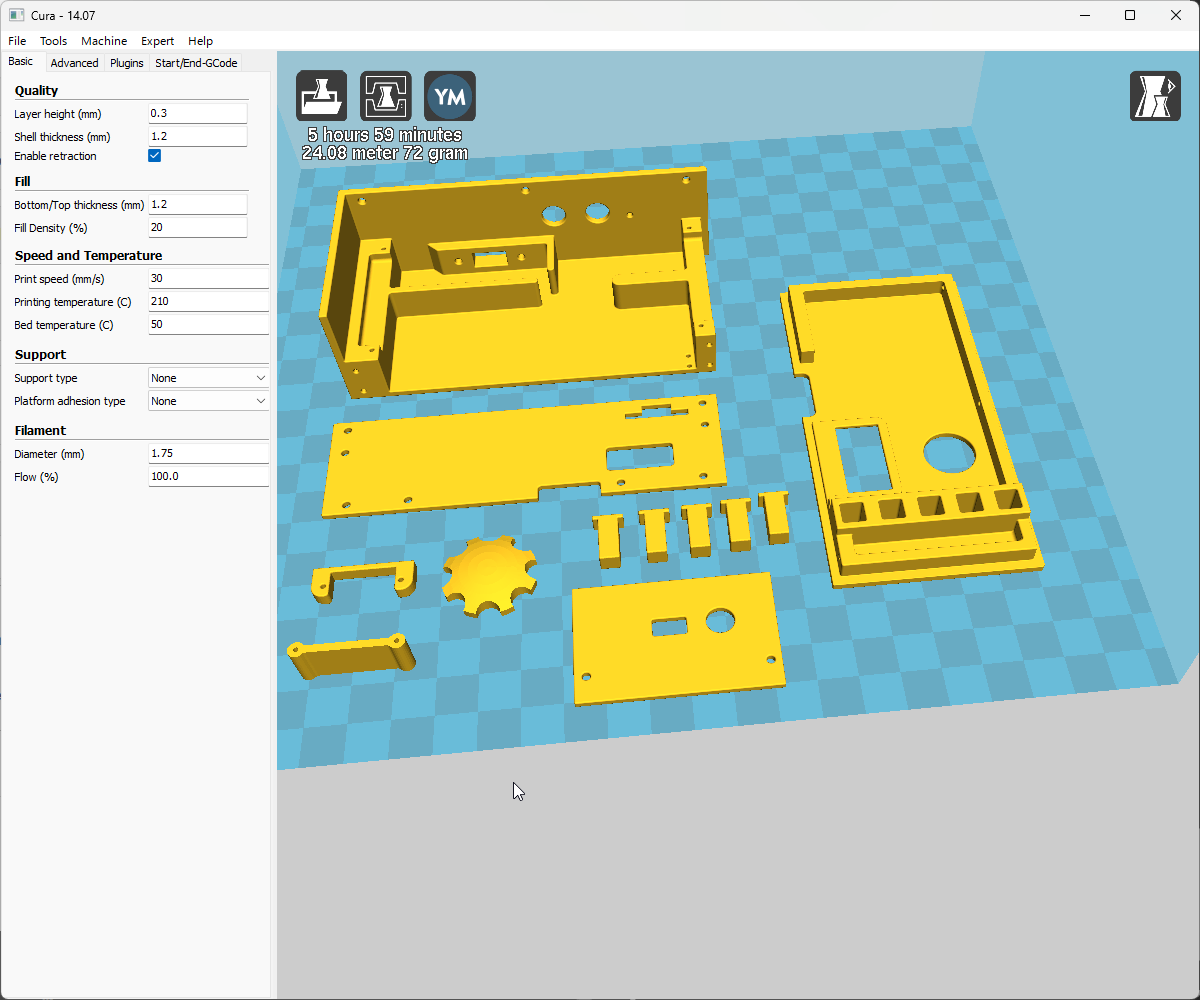
3D Prints
I have designed a simple 3D Printed box should you what to put it in a box.
- STL files for 3D printing are attached.
- Note there are 5 buttons that need to be printed.
BOM

I use "Interactive HTML BOM" to view my BOM.
Click the link to download the html file that is on my GitHub.
Once you have saved the file to your PC, open it with your web browser.
- I find it useful when I am sourcing my parts.
- Also great for keeping track when placing the parts.
The PCB

.png)
.png)


I know I have mentioned a lot, but that's where I had the PCB Made and that is basically the heart of this project.
- I use KiCAD EDA to design my PCB, and make it very easy to order a PCB.
- Just one click on there KiCAD plugin button
 and all the hard work is done for you.
 - Your order is placed on there web site and all you have to do is enter your address info and pay.
- Chose your option.
- Add to cart.
For a BOM you can download form my GitHub.
- Some of the parts I have listed above are not directly connected to the PCB.
The Microcontroller Is the STM8S103F3


There are Pads for programming the STM8S103F3
To program the STM8S103F3 will require STMicroelectronics "ST Visual Programmer"
STMicroelectronics "ST Visual Programmer" is part of "ST MCU toolset".
I have done .s19 file for use with the "ST Visual Programmer".
An ST-Link is required.
To programme the STM8S103F3P6 you will need:
- ST Visual Develop IDE from STMicroelectronics.
- ST-Link v2 from shop.
This is not an Instructable about ST Visual Develop IDE there is just enough for you to upload the firmware to the STM8S103F3P6.
The following instructions is how to upload my firmware to the PCB.
I have just put pads for programming.
- I have spaced them so that you should be able to hold a row of four 2.54mm male header pins on them.
- Programming only takes seconds.
- I prefer to solder fly-leads to the pads.
To program the STM8S103F we need to use the ST-Link v2 USB device.
The ST-Link has two ways to connect to a microcontroller.
- SWIM (Single Wire Interface Module) This is how we need to connect.
- It also can use SWD (Serial Wire Debug) this uses two communication wires clock and data (SWCLK / SWDIO)
So for us there are four wires to connect from the ST-Link and the STM8S103F.
- 3.3v
- GND
- RST
- SWIM
The connections are same-to-same.
To program the Microcontroller you will need "ST Visual Programmer" and the file.
- Here is the link to the *.s19 file required.
- Tims_DFPlayer_Plus/S19 at main · Palingenesis/Tims_DFPlayer_Plus
Programming [PROGRAM MEMORY]


Then we do PROGRAM MEMORY.
- Select the PROGRAM MEMORY tab. (1)
- Click "File" on the Toolbar. (2)
- Select: "Open". (3)
In the "Open" dialog window:
- Browse to where you downloaded the tims_i2c_duel_motor_driver.s19 file. (4)
- Select it. (5)
- Click "Open". (6)
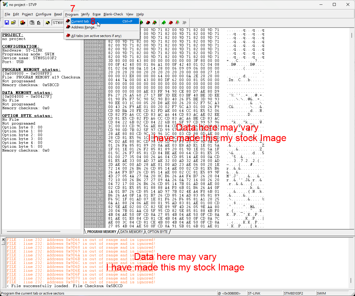
When ready:
- Click: "Program" on the toolbar.
- Select: "Current tab"
The file should upload to the Microcontroller.
Cant Program It [Locked]

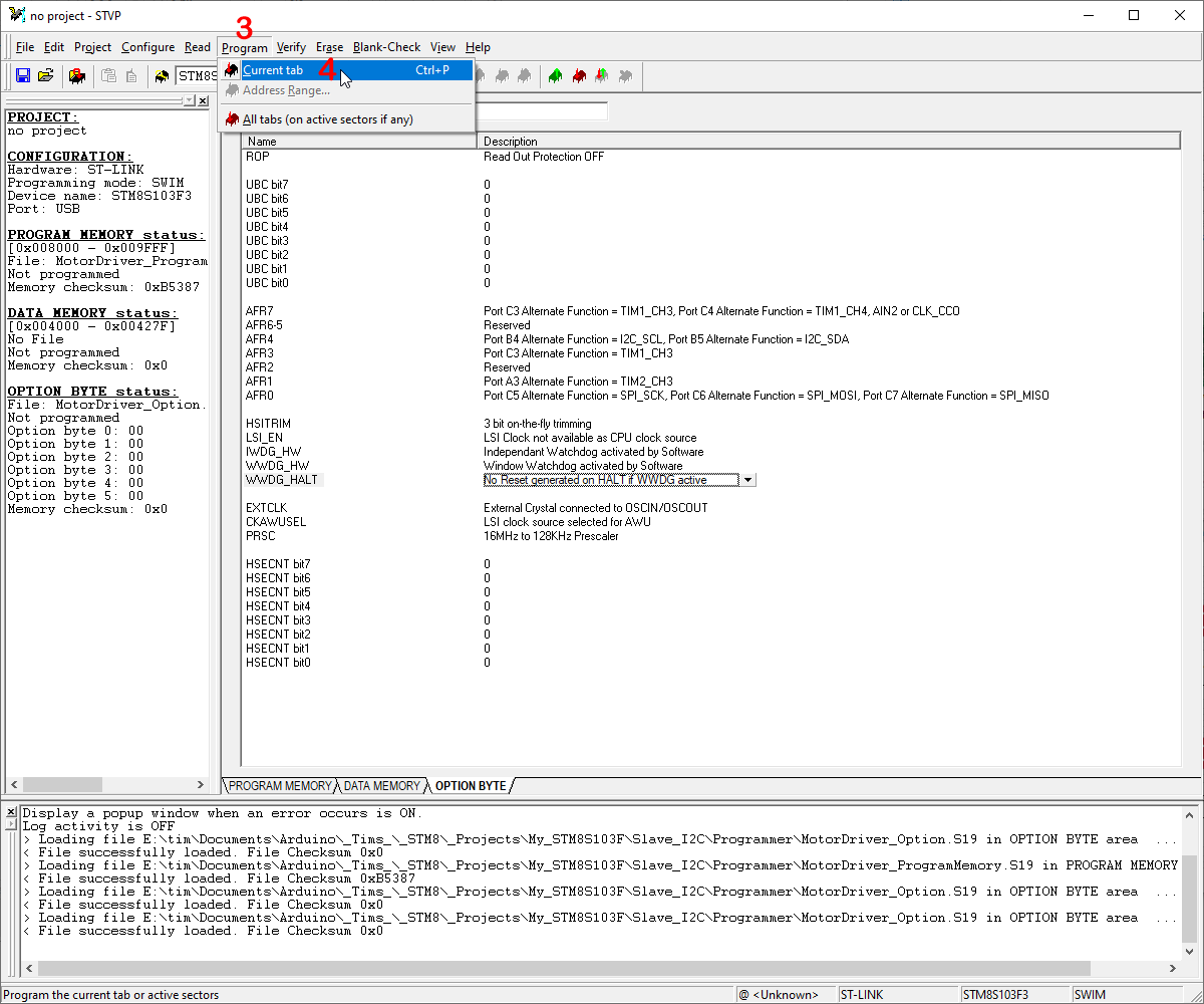
There is a third tab "OPTIONS BYTE"
If you get error microcontroller locked you need to do the following:
- Select the OPTIONS BYTE tab. (1)
- Change the "ROP" setting to say "Read Out Protection OFF". (2)
When ready:
- Click: "Program" on the toolbar. (3)
- Select: "Current tab" (4)
You should be able to do Steps 4 and 5 now.
Programming [Configuration]


Once you are connected as in Step 17.
- We are ready to start programming.
When you open "ST Visual Programmer", it is important that you have the correct Microcontroller selected.
- Make sure STM8S103F3 is selected in the dropdown box in the toolbar at the top. (A)
- This can also be selected on the configuration dialog window. (B)
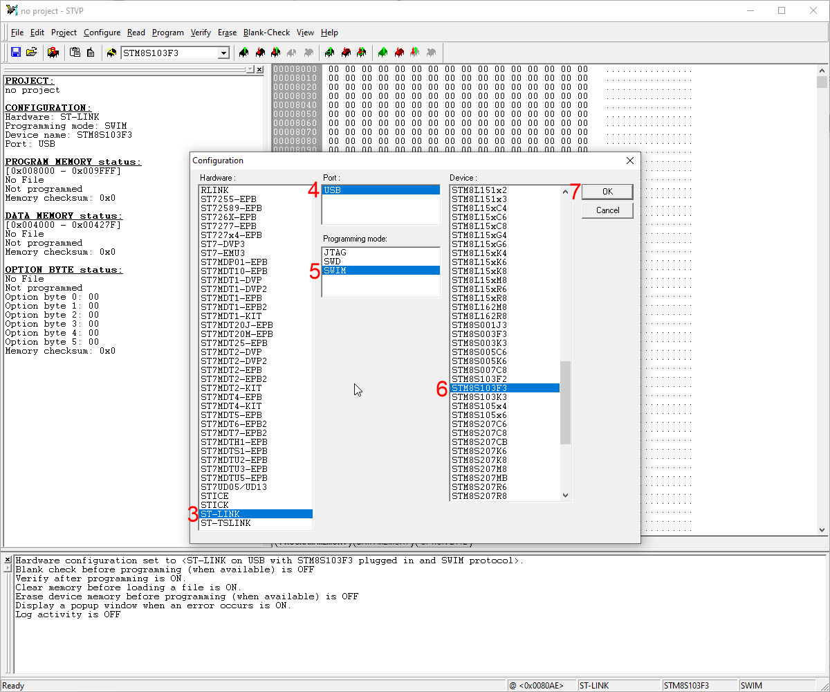
Lets use the Configuration window.
- Click Configure on the toolbar at the top. (1)
- Choose: "Configure ST Visual Programmer". (2)
- This will open the "Configuration" Dialog Window.
- Select: "Hardware" to ST-LINK. (3)
- Select: "Port" to USB. (4)
- Select: "Programming Mode" to SWIM. (5)
- Select: "Device" to STM8S103F3 (6)
- Click "OK" when done. (7)
Notes!
I have purchased several STM8S103F Modules off eBay, so far I have had both variants: STM8S103F2 and STM8S103F3. Only the STM8S103F3 work for this project.
- The difference between the two is the size of EEPROM Memory.
The Circuit

Here is the circuit for those that want to now how it is all wired together.
- The image may not be easy to read so I also attached a pdf.
The project is based around the DFPlayer.
- Instead of just adding buttons and resistors to make an MP3 Player an OLED Display has been added.
- The OLED Display is there so that specific tracs can be chosen.
- The OLED Display also enables you to set a precise volume level.
- To be able to use a display, a microcontroller is needed to control it.
- I have used an STM8S103F3P6.
- The power comes from a USB supply, but I have also placed an option to power from a 5 volt battery.
- There is a linear regulator to run the system (Vcc) at 3.3 volts.
- There is an extra amplifier added so that we can have two powered speakers and have amplified stereo.
- One should note the the amplifiers used are "Bridge-Mode" (Class a/b) amplifiers, they don't have a common ground.
- Each amplifier should have it's two output pins connected to the terminals of one speaker.
Downloads
DFPlayer Mod
.png)


.png)
.png)
.png)
.png)
.png)


A Modification is required to get two powered speaker using the Amplifier already on the DFPlayer module and the extra Amplifier we add.
As the The DFPlayer Mini Module stands as bought.
- The two DAC (Digital to Analogue Converter) channels are merged into the one mono amplifier.
- These are merged via Capacitors so they don't interfere with the DAC-L and DAC-R output output pins.
- We need to separate the merge just before the amplifier so that only one channel goes to the amplifier.
- Where we disconnect the merge we need to add a fly-lead which can plug into my PCB.
- This fly-lead will be attached to the second amplifier on the PCB.
I have attached a schematic of the DFPlayer that I have created.
- The PDF version will be better to read, but does not have the mod on it.
- The image above shows the mod.
- I have also done an image of DFPlayer where the mod is done, this is on my DFPlayer.
Note!
There are many Chinese Manufactures of this module.
- They use what ever chips that are available.
- Just recently I think they are running out of the correct chip and trying to get rid of some not so good chips.
- I have shown the chip that is on the DFPlayer that I have.
- There is also an image of one that I got recently, it is s**t, it only has one DAC, there is no way you can get stereo from it.
- See my video Tim's DFPlayer Plus [I got the PCB]
I have gone into details on my video here: Tim's DFPlayer Plus [Talking about it] - YouTube
- If you have a different version of the DFPayer, you may want to watch the video to get an idea what heeds doing.
- The circuitry should be the same but the components may be positioned in a different place.
- It will be a matter of tracing both DACs from the large chip to the amplifier.
- Once you find the merge, that's where you need to make the mod. (providing the min chip is stereo)
Downloads
Battery Mod


You can make it Battery powered.
- I have used off the shelf parts to do this.
- This is how I add battery power to most of my projects.
I have added a battery charger (HW-107) the type that has battery protection also.
- This charges the battery via a Micro USB.
There is a switch of course.
- We need to be able to switch it on and off.
There is a boost to boost the battery voltage up to 5 Volts.
- I have set to voltage to 5 volts to make it easy using multiple power supplies.
Some cable it needed to wire it all together.
- I have done a fritzing to show how it all goes together.
- The two wire DuPont connector goes to the pin header on the PCB.
The Case
![Tim's DFPlayer Plus [The box]](/proxy/?url=https://content.instructables.com/FTU/EL2S/M5FC6NSE/FTUEL2SM5FC6NSE.jpg&filename=Tim's DFPlayer Plus [The box])

Should you wish to make a case for it.
- I have designed one to be 3D Printed.
- If you don't have a 3D Printer do a service.
The case is taller than the PCB Assembly because I have made room for the battery and charging components.
I have also shown the orientation I printed the parts.
- I printed the parts where I could with the outer side to the bed.
- I get a nice flat finish on the bed side.
Putting It All Together [Switch]


Once you have the Battery component all wired up.
- The first thing is to fit the switch.
- My switch only has mounting holes, they are not treaded.
- I have made a Switch_Retainer.stl so that the switch can be held in place by two M1.7x10mm self tapping screws.
Putting It All Together [Battery/Charging]

Next place the rest of the Rechargeable Battery components.
- These I just held in place with some contact adessive.
Note
Have the Back_Pannel.stl to hand.
- The HW-107 Battery charger is fitted upside down, this is so the LEDs can be seen from the underneath.
- The HW-107 Battery charger does not have the USB socket extended.
- I had to make it so the whole HW-107 fitted flush with the Back_Pannel.stl.
- So when gluing it in place, hold the Back_Pannel.stl in position while is is set in place.
Putting It All Together [PCB]

The PCB can now be fitted.
- Use four M1.7x6mm screws to hold it in place.
Note
The top of the Battery needs protecting from the component pins sticking through the PCB.
- Use some thick card or plastic sheet, and place it over the battery.
Putting It All Together [OLED]


The OLED needs the OLED_Support.stl.
- Fix the OLED_Support.stl using two M1.7x6mm screws.
The OLED Display can now be fitted to the PCB.
Putting It All Together [MP3 Player]
.png)


Plug the Fly-Lead from the modified DFPlayer Mini onto the the Header pin on the PCB.
- Then plug the DFPlayer Mini into it's socket on the PCB.
- Be sure to get the correct orientation.
- The SD Card should be facing the outside.
Putting It All Together [Side Panel]

Fix the Side_Pannel.stl using two M1.7x6mm screws.
Putting It All Together [Back Panel]

Fit the Back_Pannel.stl using four M1.7x6mm screws.
Putting It All Together [Top]

To fit the Top.stl it may be best to hold the assembly up side down.
- First insert all five Button,stl into the Top.stl.
- Then fit the Top.stl to the main assembly.
- Use seven M1.7x6mm screws to hold it in place.
Putting It All Together [Knob]

The Knob.stl should be a snug fit on top of the rotary encoder.
Ready to Go

