Tinkercad Blinking LED Lights
by jashendharni in Circuits > Arduino
271 Views, 1 Favorites, 0 Comments
Tinkercad Blinking LED Lights
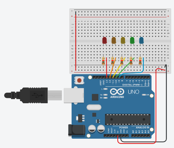
TEJ2O1 Culminating Assignment - Jashen
I think different colored lights are cool, and this is the best I think I've done while doing it off of 1 video.
Supplies

1 Arduino Uno R3
5 LED lights (colors of your choice)
Jumper Wires (I used 9 wires of different lengths)
5 Resistors (I used 1kohm)
1 Breadboard
Connect the Breadboard to the Arduino Circuit
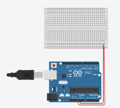
Our first step is to connect our Arduino board with our breadboard. The breadboard doesn't have any power, when we connect and code through the Arduino, we need to send the connection to the breadboard.
The red wire above connects our 5V (Arduino) to the breadboard positive power rail.
The black wire above connects a GND (Arduino) to the breadboard negative power rail.
This will make sure whatever happens on either board will be able to be read by the other board.
Adding the LEDS, Resistors, and Wires
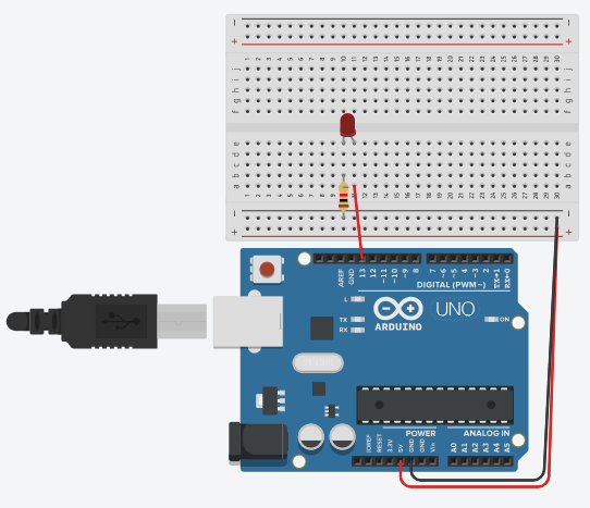
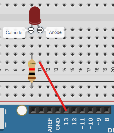
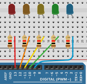
After connecting the breadboard and Arduino, we add in our LEDs, resistors, and wires.
The LED has an anode and cathode part. The anode and cathode will take up 2 columns. In our case, I added it to 10 and 11.
We then add in a resistor between the negative power rail and the second last hole on the cathode column. We do this because we don't want the LED to burnout or take in an unnecessary amount of current.
A wire is added from the last hole in the anode column to D13 on the Arduino. We add it to the Arduino so that we can code the Arduino to make a pulse pattern.
Repeat this step 4 more times to add the rest of them. I added mines for reference on how to do it with the code I provided.
Coding the Arduino
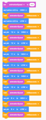
Coding the Arduino is kind of easy if you already know it. I didn't so I'll show you how to do it in blocks and in code.
I made a variable called "animationSpeed" and made it 400milliseconds. The built in LED is the first one that we had added so we already wrote that it will pulse. I then added in for it to wait animationSpeed milliseconds. I added in digitalWrite (pin#) HIGH so that it knows to turn on. I added in another wait so it can stay on for a bit, then added in another digitalWrite (pin#) LOW so it turns off. I repeated this step for every other pin except for 13 since thats our built in one.
You're DONE!
You should now get something like I included here.
Troubleshooting
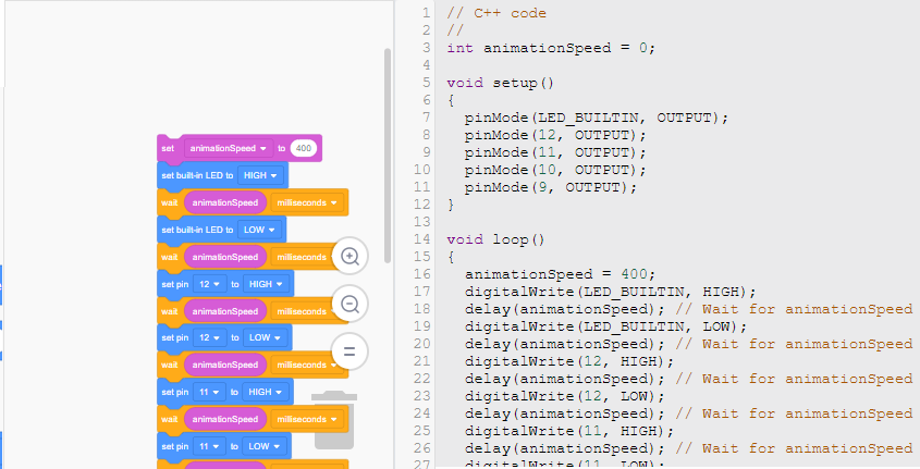
Even though this is an almost fail proof project, there still may be issues.
LED not turning on?
- Check if the breadboard is connected
- Make sure the code has the right numbers on there (pin13,pin12, etc.)
- Double check if the wires are connected in the right areas.
Code not working?
If the code isn't working, I recommend to go check the video on how to do it on blocks instead. Blocks are easier to use for beginners and more organized in my opinion.