Tinkercad - Book Storage Container for RPG Condition Rings
by RoguePirin in Workshop > 3D Printing
1547 Views, 27 Favorites, 0 Comments
Tinkercad - Book Storage Container for RPG Condition Rings


For me, condition indicators are a great way to help remind everyone what condition is afflicting each character (friend or foe) on the table. After finding models for these online, I printed and painted 40 of them. I soon realized that a random box full of 40 condition indicator rings was not ideal, and I wanted a more organized way to store and retrieve them. I designed my own container, deciding to model it after a book.
Here, I will detail my process for creating my storage book. I will include details on my decisions, which should allow you to adapt them to meet your needs, if you have a different quantity of indicators to store or if you use different sized indicators (printed or commercially purchased).
Supplies
- Tinkercad (for design and 3D modelling)
- 3D Printer
- 2 disc magnets
- metal flashing (or any thin metal that magnets stick to)
- Primer and Paint
Design Considerations

After having decided upon a book shaped container, I had to consider the following:
- How many total rings does the book need to hold, and in what configuration?
- What is the overall size of the book?
- Do I want the book to latch closed, and if so, via what mechanism?
1. Book Layout
I already had my collection of 40 condition indicators (rings), so I knew how many rings needed to be stored. Upon closer examination, I notice that I printed each condition in quantities of either 2 or 4; I had 10 conditions with 2 rings, and 5 conditions with 4 rings. If I doubled up on the 2-ring conditions, I would end up with 10 stacks of 4 rings.
I grabbed a collection of actual books off the bookshelf, and placed all 10 stacks on them to find a general layout that resulted in a book that wasn't too big, but also left enough space for my fingers to reach in and grab a ring without running into the other stacks. Depending on how many rings/stacks you have, your configuration could be different.
2. Book Size
The size of the book was determined by the layout of the 10 stacks. I decided that I did not need finger space to the left/right of each stack on the outside, as long as there was finger space above/below them. The opposite went for the top and bottom of the central stack, no finger space need above and below if there was finger space on the sides. Based on the actual books that I had, and the layout of the 10 stacks, it worked to have the inside space of the book to measure 140mm x 216mm.
As for the inside book height, I measured how tall 4 condition rings stacked up, and added 1mm for tolerance (the next section details how I came to 20mm high for the posts; adding 1mm for tolerance so the book cover doesn't lay on the top of the posts yields an overall inside height of 21mm).
I had to decide how thick I wanted the book walls. I made the cover and spine 3mm thick, since those pieces incorporate the hinge and I would interact with/manipulate that the most. The remaining sides are 2mm thick.
Finally, I wanted the cover of the book to extend out past the edges of the inside "pages" area. I made the cover extend 3.4mm past each "page" section wall. This yielded an overall outside book dimension of 148.4mm x 226.8mm.
3. Book Latch
I didn't get too fancy here. I did give some consideration to a physical clasp on the book, but I wasn't confident in its longevity (or my design skills). I decided to keep it simple and use magnets and metal sheeting.
Modeling the Condition Ring Posts


The inside hole of the condition rings are 1" (25.4mm) in diameter. I didn't want the rings to fit too snugly on the posts, so the posts were designed to be 24mm in diameter. Since a stack of 4 rings is 18.5mm high, the posts need to be at least 18.5mm high. I wanted to add a simple bevel at the top so the rings slide on/off a little easier, which I made 0.75mm. So far, the posts need to be 19.25mm high; rounding that up results in a post being 20mm tall. For easier (overlapping) alignment with the 2mm backing of the book, I added that thickness to the posts for a total post height of 22mm.
To design this in Tinkercad, create/open your project and follow these steps:
- From the Basic Shapes menu on the right, select the solid Cylinder
- Click on a blank space on your Workspace to create the cylinder
- In the menu that comes up, set the parameters to the following
- Increase the Sides to the maximum of 64 for the smoothest cylinder
- Set the Bevel to 0.75 mm
- Leave Segments at 1
- On the cylinder itself, select one of the 4 boxes at the corners of the XY plane (the Workspace)
- Set the value for the width and depth to be 24.00 each.
- Select the single box at the top of the dashed line representing the Z axis and set the cylinder height to 22.00 [ring post]
You may notice that when you set the Bevel value to 0.75, that both the top and bottom of the cylinder get beveled. This is OK, because we will be sinking the cylinder into the 2mm back of the book, and it will merge together and the bottom bevel will disappear.
Modeling the Book Hinges


For the hinge, I decided that I wanted the tabs to be 19mm each. However, I was concerned that the tabs would rub together if I didn't put a small gap between them, so I decided to put 0.1mm of space between them. Since that 0.1mm space is shared between adjacent tabs, each tab needs 0.05mm of space on each side, or 18.9 mm wide overall. Based on my overall book size of 226.8mm, I need 12 tabs (12 x 19mm = 228mm). I opted for 13 tabs, because I wanted 7 on the base and 6 on the cover so that there were tabs on both ends of the base. Therefore, the overall hinge needs to be 247mm long.
For the hing pin itself, I wanted to use unfolded paper clips so that the pin is metal. The medium paper clips that I have are just over 1mm in diameter. Knowing that I would not be able to perfectly straighten out a bent paper clip, I decided to make the pin hole in the hinge 1.5mm in diameter. For sturdy hinge tabs, with a 1.5mm hole in them, I went for 3mm diameter outside hinge. The tabs need to be elevated higher than the edge of the book so that the cover will sit flush on the edges when the book is closed. Therefore, the tabs need to extend 3mm above the sides of the book.
With the back of the book being 2mm thick, the sides being an additional 21mm high, and the hinges extending 3mm above that, the hinge/spine of the book needs to be 26mm tall.
Here's how I made the rounded spine/hinge panel in Tinkercad:
- Create a box that is 247mm long, 3mm wide, and 24.5mm tall (It should be 23mm, with a 3mm hinge cylinder, but I want to extend it 1.5mm higher so that it merges cleanly with the hinge cylinder)
- Create a cylinder that is 247mm long, 3mm wide and 3mm tall. Be sure to increase the sides to 64. Lastly, rotate the cylinder 90 degrees so that it runs parallel to the box.
- Select the cylinder, copy it, paste it, and change the width and height to 1.5mm. Extend the length to 260mm. Lastly, change this narrow cylinder from a solid to a hole.
- Select the box and both cylinders and chose the Align tool. Center align them along the 3mm width; Top align them along the height, and end align them along the length. Now select only the box and move it down 1.5mm. Now select only the 2 cylinders and center align them along the height. Lastly, select the box and both cylinders and group them together.
Here's how I made the tabbed spine hinge out of the rounded spine/hinge panel
- To make 18.9mm tabs, spaced 19mm apart, I needed to cut out19.2mm sections periodically along its length. The first picture shows my notes and how I came up with the values.
- Create a Hole box that is 19.2mm long, 3mm wide and 3mm tall.
- Copy and paste that 5 times so that you end up with 6 hole box pieces.
- Select the rounded spine/hinge and all 6 hole box pieces. Select the Align tool and line them up at one end.
- One at a time, select one of the hole box pieces and move it away from the edge 18.9mm, 56.9mm, 94.9mm, 132.9mm, 170.9mm and 208.9mm.
- Select all 6 hole box pieces and chose the Align tool. Center align them along the width and height, but do not change their location along the length. Once aligned, group all 6 into a single hole boxes piece.
- Select the rounded spine/hinge panel and the single hole box pieces. Choose the Align tool and align the pieces along the top for the height and the center for the length and width.
- Group both pieces into a single book spine hinge.
Copy and past the tabbed spine hinge so that you now have 2 of them.
With the first tabbed spine hinge, we need to trim it to size to fit the book. The book is 226.8mm long and the tabbed spine hinge is 247mm long; giving an excess of 20.2mm. Splitting that excess over both ends, so that there is some tab on each end, yields a cropping of 10.1mm off each end.
- Create 2 hole boxes that are 10.1mm long, 3+mm wide, and 26+mm high.
- Select 1 hole box and the tabbed spine hinge and chose the Align tool. Align the hole box with one end of the tabbed spine hinge, ensuring that it covers the hinge in height and width. Group the 2 objects.
- Select the 2nd hole box and the tabbed spine hinge and chose the Align tool. Align the hole box with the other end of the tabbed spine hinge, ensuring that it covers the hinge in height and width. Group the 2 objects. [spine hinge]
Now that the tabbed spine hinge is complete for the book base, we need to create the tabbed hinge for the cover. The tabbed hinge cover needs to start without any tabs, since the book spine hinge starts with tabs. To do this, we will start with the tabbed spine hinge that we copied earlier and add a spacer up front to offset the tabs. In the previous actions, we trimmed the spine tabs 10.1mm. Since each tab is 18.9mm long, the remaining tab that starts the spine hinge is 8.8mm. Our design calls for a 0.1mm gap, so we will add an 8.9mm spacer to the hinge for the cover.
- Create a box that is 3mm wide, 23mm tall, and 8.9mm long
- Select the copied tabbed spine hinge and the newly created box and chose the Align tool. Align both objects on one end and center on the width and height.
- Select just the copied tabbed spine hinge and move it along its length 8.9mm
- Select both objects again and group them.
- Now that the tabbed cover hinge is offset correctly, the other end needs to be trimmed to length.
- The tabbed cover hinge is now 255.90mm long, so create a hole box that is 29.1mm long (255.9 - 226.8), 3+mm wide, and 26+mm high.
- Select the tabbed cover hinge and the hole box and chose the Align tool. Align them to the other end of the cover hinge, ensuring that it covers the hinge in height and width. Group the 2 objects. [cover hinge]
This completes the cover hinge. To ensure that everything is correct, select both the spine hinge and the cover hinge and select the Align tool. Align both objects along the center for width, length and height.
Building the Base of the Book


The overall dimensions of the book base are 148.4mm x 226.8mm x 26mm. Note that the 26mm height includes 3mm protrusion of the hinge, so excluding that, the book base is 23mm high, including the 2mm back cover.
To model the back cover of the book, I decided not to include the 3mm hinge, so its dimensions are 145.4mm x 226.8mm. In Tinkercad:
- create a solid box and set its dimensions to 145.4 wide, 226.8 long and 2.0 high. [back cover]
- create another solid box and set its dimensions to be 140.0 wide, 2.0 long and 23.0 high. [bottom side]
- create another solid box and set its dimensions to be 140.0 wide, 2.0 long and 23.0 high. [top side]
- create a 4th solid box and set its dimensions to be 2.0 wide, 226.8 long and 23.0 high [right side]
- to round the corners of the 'right side' piece, create a solid box with dimensions 10.0 x 10.0 x 26.0 high [corner round box]
- create a cylinder hole with dimensions 4.0 x 4.0 x 26.0 high [corner round cylinder]
- select the [corner round box] piece and the [corner round cylinder] piece and select the Align tool. Align the pieces to the lower left and centered in height.
- select only the [corner round box] piece and move it 2.0mm up and right away from the [corner round cylinder] piece so that the corner of the [corner round box] piece is at the center of the circle of the [corner round cylinder] piece.
- select both the [corner round box] and [corner round cylinder] pieces and group them together. Finally, with the newly grouped piece selected, change it from a Solid to a Hole piece. [corner round]
- copy and paste 5 copies of the [corner round] piece so that you have a total of 6 of them
- to round the corners of the [right side] piece, place one copy of the [corner round] piece at each end. Rotate the [corner round] piece the correct amount so that the cutaway circle faces the respective corner of the [right side] piece.
- Using the Align tool, align each [corner round] piece with an end of the [right side] piece. Once done, shift each [corner round] piece 8mm away from the edge of the [right side] piece so that the cutaway circle overlaps the very corner point.
- Select the [right side] piece and both [corner round] pieces and group them together. [rounded right side]
- To put all the pieces together, select the [spine hinge] and the [back cover] and select the Align tool. Align both pieces along the bottom left corner of the [back cover], ensuring that both pieces are at 0.0 height off of the workspace; this will show the [spine hinge] sunk 2mm into the [back cover]. Selecting only the [back cover] piece, move it 3.0mm right so that the [spine hinge] and [back cover] are butted against each other.
- Move the [bottom side] piece on top of the [back cover], selecting both and then select the Align tool. As long as the [bottom side] is located entirely within the [back cover], choosing an alignment location will only move the [bottom side] piece, leaving the [back cover] aligned with the [spine hinge]. Align the [bottom side] to the bottom left corner of the [back cover], ensuring that both pieces are at 0 height off of the workspace; this will show the [bottom side] sunk 2mm into the [back cover]. Selecting only the [bottom side] piece, move it 3.4mm up towards the center of the book.
- Move the [top side] piece on top of the [back cover], selecting both and then select the Align tool. As long as the [top side] is located entirely within the [back cover], choosing an alignment location will only move the [top side] piece, leaving the [back cover] aligned with the [spine hinge] and [bottom side]. Align the [top side] to the top left corner of the [back cover], ensuring that both pieces are at 0 height off of the workspace; this will show the [top side] sunk 2mm into the [back cover]. Selecting only the [top side] piece, move it 3.4mm down towards the center of the book.
- Move the [rounded right side] piece on top of the [back cover], selecting both and then select the Align tool. As long as the [rounded right side] is located entirely within the [back cover], choosing an alignment location will only move the [rounded right side] piece, leaving the [back cover] aligned with the [spine hinge], [bottom side] and [top side]. Align the [rounded right side] to the right center of the [back cover], ensuring that both pieces are at 0 height off of the workspace; this will show the [rounded right side] sunk 2mm into the [back cover]. Selecting only the [rounded right side] piece, move it 3.4mm left towards the center of the book. This should align it with the edges of both the [top side] and [bottom side] pieces.
- Select all 4 side pieces and the back cover and group them. [book base]
- To round the outer edges of the [book base] piece, we'll do the same steps as above for rounding the edges of the [right side piece]. Use 2 more of the [corner round] pieces we created to align them to the top/bottom corners of the [book base]. Rotate them accordingly and move them outward 8mm. Once in position, group the [book base] and 2 [corner round] pieces.
Adding Latch Magnets to the Book Base


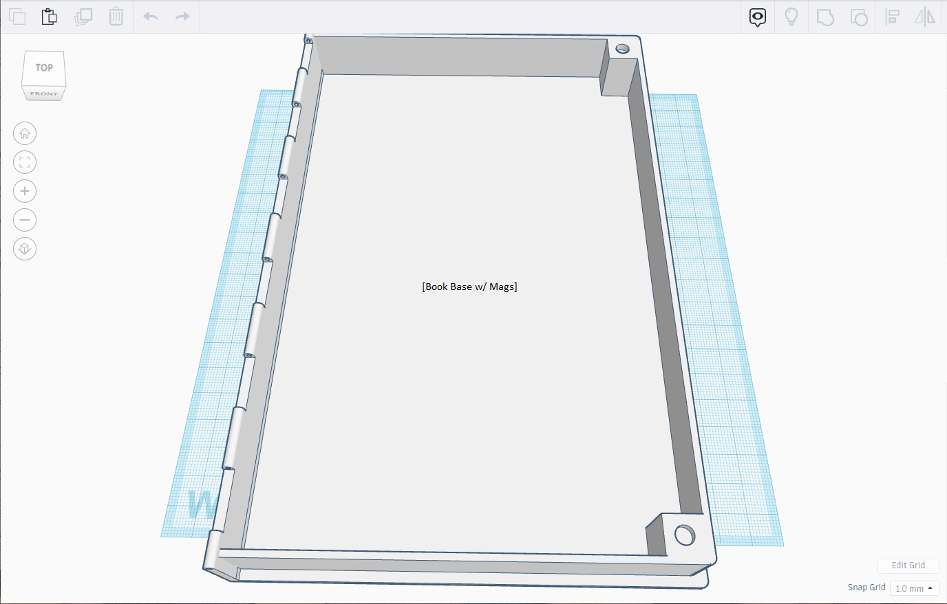
To keep the book closed, I decided to put magnets in the base, and strips of metal in the cover. I happened to have 6mm round disc magnets that are 3mm thick. Change your design if you have different magnets.
For the 6mm magnets in the base:
- Create a Solid Box piece that is 12.0 x 12.0 x 23.0 [magnet box]
- Create a Hole Cylinder piece that is 6.0 x 6.0 x 3.0 [magnet hole]
- Select the [magnet box] piece and the [magnet hole] piece and select the Align tool. Align the pieces to be centered on the width and length and at the top for the height.
- With both pieces selected, group them [magnet holder]
- Create a second copy of the [magnet holder] piece using copy/paste
- Place one [magnet holder] piece onto the [book base] in the lower right corner, and one [magnet holder] piece in the upper right corner. User the Align tool to align them both completely in each corner, aligned at the bottom for the height so that each [magnet holder] piece sinks into the [book base] by 2mm.
- Select and move each [magnet holder] piece towards the center of the book by 5.4mm along both the width and length (2 mm wall thickness, plus 3.4mm extension for the cover)
- Group the [magnet holder] pieces with the [book base] piece [book base w/ mags]
Adding the Condition Ring Posts to the Book Base


For my condition ring collection, I need 10 [ring post] pieces.
- Select the [ring post] piece that was created earlier
- Select the Copy action, followed by 9 Paste actions.
- Move all 10 [ring post] pieces onto the [Book Base w/ Mags] piece.
- Layout your [ring post] pieces to match your layout.
- I chose to do 3 columns of posts, with 3 posts, 4 posts and 3 posts.
- Align each column of [ring post] pieces centered on the length.
- With each [ring post] being 24mm in diameter, and using 24mm of space between each column left-to-right, we are left with 10mm of space on the far sides of each column of posts.
- Select one column of 3 [ring post] pieces and align them to the left of the [Book Base w/ Mags] piece. Then, with the column of pieces selected, move them right 13.00mm (this will account for 3mm of the spine plus the 10mm gap).
- Select the other column of 3 [ring post] pieces and align them to the right side of the [Book Base w/ Mags] piece. Then, with the column of pieces selected move them left 15.4mm (this will account for the 3.4mm of overlap, the 2mm side thickness, and the 10mm gap).
- Select the column of 4 [ring post] pieces and align them with the left of the [Book Base w/ Mags] piece. Then, with the column of pieces selected, move them right 61mm (this will center them within the 140mm inside opening of the book base.
- For the vertical layout, I decide to use the same 10mm of space at the far top and bottom of the center column of 4 posts. With 24mm posts in that central column, that yielded ~33mm of space between the posts vertically.
- Also, for symmetry, once the vertical layout of the central column was defined, I used the same vertical spacing for the other columns and aligned them with the center of the gaps between the posts of the central column
- To align the outside columns of 3 [ring post] pieces each, select one column at a time and align them with the bottom of the [Book Base w/ Mags]. Then, move one of each of the 3 [ring post] pieces up 44.05, 101.36 and 158.66mm.
- To align the center column of 4 [ring post] pieces, select the column of pieces and align them with the bottom of the [Book Base w/ Mags] piece. Then, move one of each of the 4 [ring post] pieces up 15.4, 72.7, 130 and 187.4mm
- Select all [ring post] pieces and the [Book Base w/ Mags] and Group them together [Final Book Base]
You can stop here for a universal condition ring holder base, but I wanted to customize mine for the specific collection of condition rings. I labeled each ring post with the name of the condition ring(s) that sit around it. For 3D printing, I find that small text comes out better if it is removed from the object rather than printed on top of it.
- Create a TEXT object and set the text to the name of your label. I chose the SANS font, as it prints best with my 0.4mm nozzle when this small. I chose the resize the font, maintaining the aspect ratio, to 20mm wide; this yielded a text height of 2.68mm. I set the depth of the text to be 1mm, as that is how deep I wanted the text to sink. **To maintain the aspect ratio when resizing the text, hold down the SHIFT key on the keyboard when you click and drag the corner to resize it. [Label Text Solid]
- With the [Label Text Solid] piece selected, changed the type from Solid to Hole. [Label Text Hole]
- Select the [Label Text Hole] piece and move it over the desired ring post. Select and drag the up arrow to set how high off of the workspace the object is. I placed my text 21mm off of the workspace, as the posts are 22mm tall and I wanted the text sunk 1mm.
- Repeat this for each label you wish to create.
- Once all labels are created and aligned over the {Final Book Base], Group them. [Final Labeled Book Base]
Designing the Book Cover

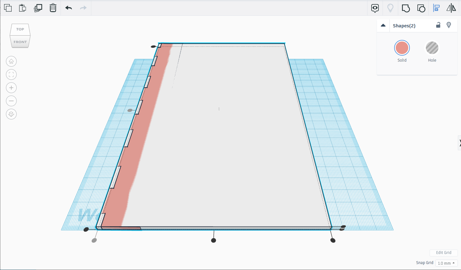


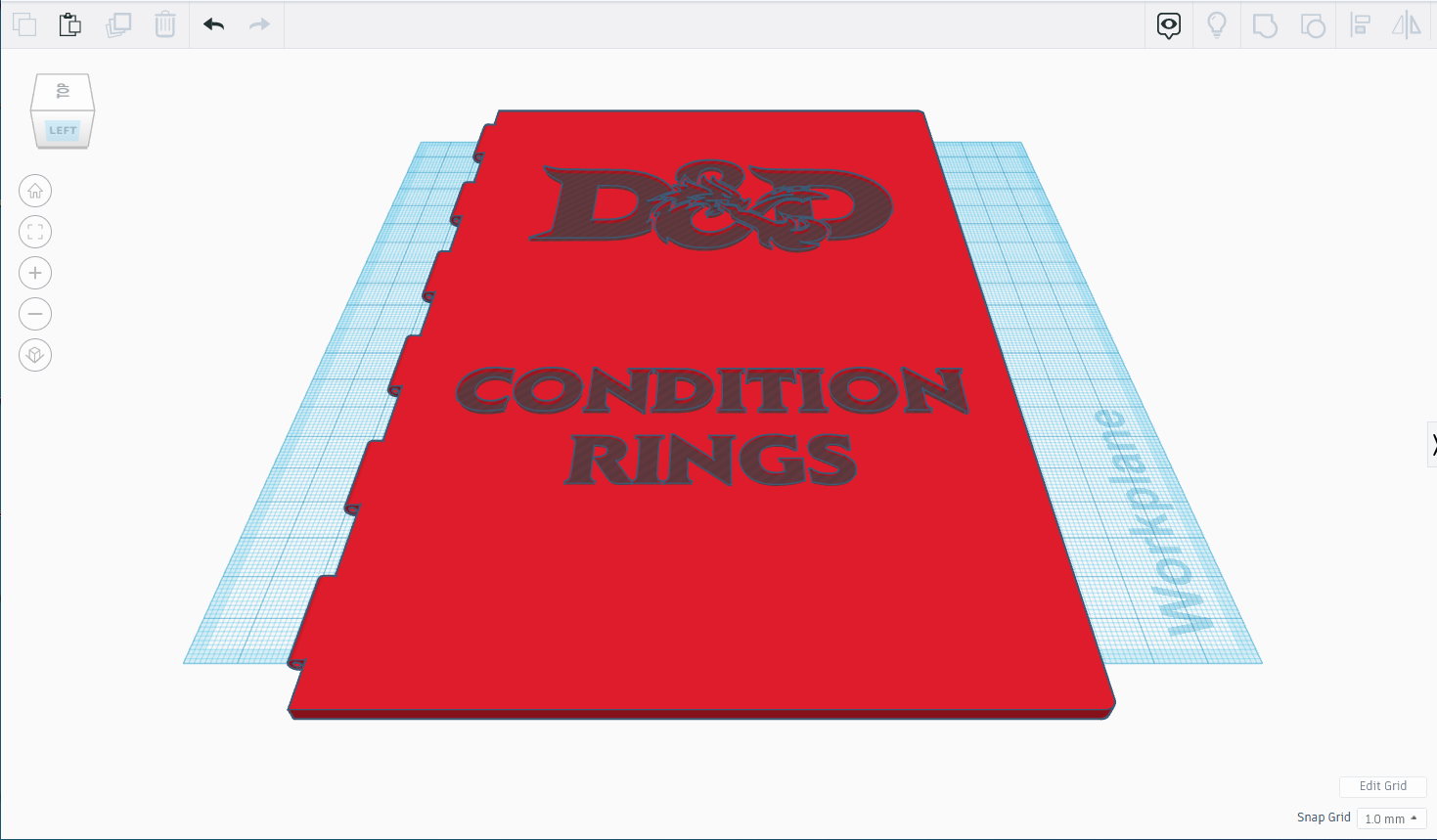

The book cover needs to be the same size as the [book base] (148.4mm x 226.8mm), and due to the hinge thickness will be 3mm thick.
- Starting with the [cover hinge] we made earlier, rotate it so that it lays flat and the hinge is on the left.
- Create a box that is 140mm x 226.8mm x 3mm [cover span]
- Select the [cover hinge] piece and the [cover span] piece and select the Align tool. Align both pieces centered on the length and height, but aligned left on the width.
- Selecting only the [cover hinge] piece, move it 8.4mm to the left.
- Group the [cover hinge] and [cover span] pieces.
- Round the edges of the right side of the cover the same as before, using the last 2 [cover round] pieces. [one cover]
- Select the [one cover] piece and rotate it 180 degrees so we see the back side.
- Create two Hole boxes that are sized for your metal pieces for the latch. Since the [magnet holder] pieces are 12mmx12mm, I made my hole boxes 12mm x 12mm. The metal flashing I chose to use measured 3.4mm thick, so I made the hole boxes 0.4mm deep.
- To line the 12x12 hole boxes over the [magnet holder] pieces, align each hole box into each corner of the [one cover], not including the hinged corners. Then move each hole box 5.4mm in toward the center of the [one cover] in the width and length.
- Lastly, select both hole boxes and the [one cover] piece and choose the Align tool. Choose only to align them in height. Combining all 3 object then yields two square depressions in the back of the cover.
At this point, the generic cover is finished. I chose to embellish my cover by adding a logo and some text.
- I selected the back cover and rotated it 180 degree so that the front was face up.
- Then I chose the Import command to load a 3D model of the D&D logo into Tinkercad; I found the model on a 3D printing website.
- Once the model was imported, I selected it and changed its type from a Solid to a Hole.
- I also found a D&D type font online and created my text with it in Inkscape. I saved the text as an SVG file, and Imported that into Tinkercad. Again, I changed its type form a Solid to a Hole.
- I placed the logo and text above the cover and sized and positioned them until I was satisfied. Remember to hold down the shift key when resizing to maintain the aspect ratio
- I made the log and text 2mm deep. I then set them to be 2mm off the work surface so that they sunk 1mm into the cover.
- Finally, I selected the cover, logo and text and grouped them.
Putting It All Together - Real Life Results
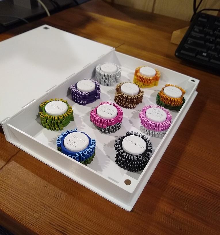
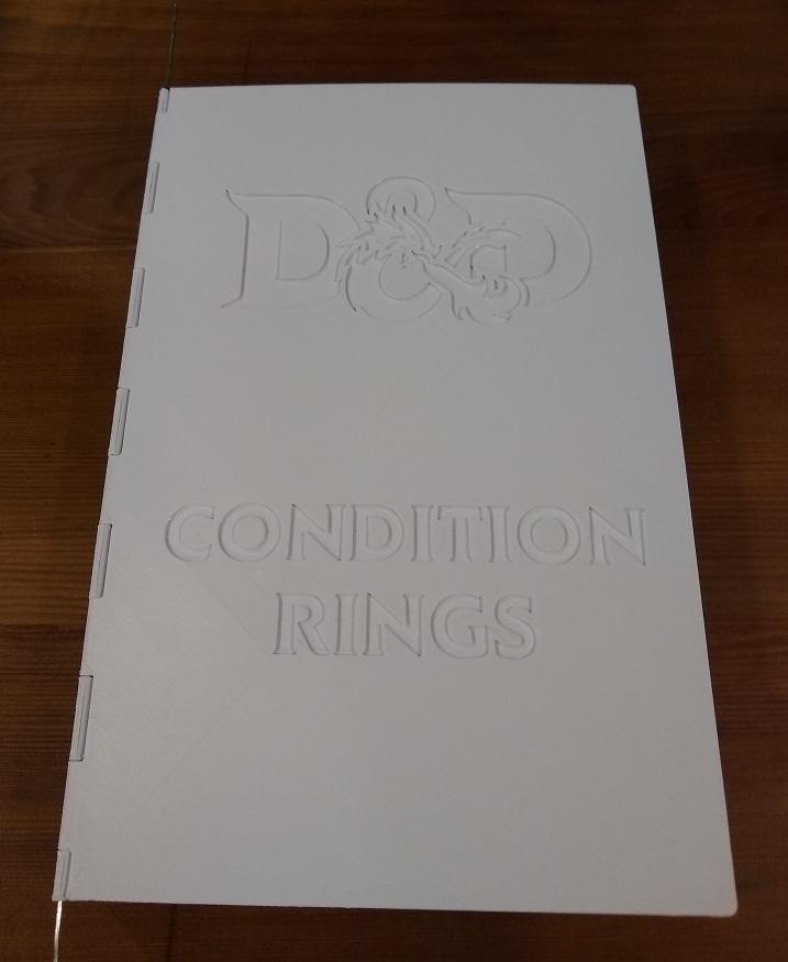


From model to reality:
- I printed the book base and book cover on my FDM printer, using white PLA. Neither piece needed supports.
- I placed a little super glue into the holes on top of the magnet holders and then press fit the magnets in place.
- I cut two small squares out of home duct flashing. Cutting them caused the edges to curl up, so I pounded them flat with a hammer. I then used super glue to affix them inside the recessed squares in the cover.
- After the glue was dry, I set the cover on top of the book base and pushed the hinges together; the magnets engaged and help keep everything closed and aligned.
- I unfolded two medium paper clips until they were mostly straight. I inserted one paper clip into the hinge hole at the bottom and pushed it through each tab, twisting the clip as it reached each new tab. I only pushed one paper clip in as far as half the height of the book. I took the second paper clip and followed the same procedure to slide it halfway down the hinge, starting at the hinge hole at the top.
- With this assembled, I opened and closed the book several times, ensuring smooth operation of the hinge and proper latching of the magnets to the metal flashing.
- Once the dry fit was successful, I removed both paper clips and separated the book pieces.
- I then primed and painted the entire front cover, as well as the hinge, spine and back of the base cover in plain red. I was careful not to prime or paint any parts that I wanted to stay white. I did make a few mistakes and got some red paint into the recessed lettering, but I touched that up with some white paint where needed.
- Once all the paint was dry, I put the paper clips back into the hinge. With there position set, I marked each paper clip at the point where they exiting the hinge. I then pulled the paper clips out about 15cm and cut the paper clip just past its mark. Then I put some super glue on the end of the paper clip and pushed it fully back into the hinge (I used the piece of paper clip that I cut off to prevent getting super glue on my fingers). If you do glue the paper clips into your hinge, but sure that the glue does not go into the hinge past the first tab, or the hinge won't rotate. I did the same to the paper clip on the other side of the hinge.
...and there you have it! If you made it this far, thanks for sticking around. I hope you found this interesting and, if you decide to try it yourself, I hope it is easy enough to follow.