Tinkercad Finger Focus Highlighter by Accessing Potential
by Accessing Potential in Design > 3D Design
201 Views, 0 Favorites, 0 Comments
Tinkercad Finger Focus Highlighter by Accessing Potential

We provide step by step instructions on drawing your own Finger Focus Highlighter 3D model using TinkerCAD. This simple project is created to help 3D printing beginners start designing their own 3D models.
Supplies
Caliper
Measuring Tape
Reading material
Set Up Workplane
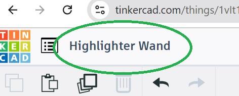

Change the name of your project in the upper left of the workplane.
If your units are not in millimeters, select Settings (in the bottom right of your workplace) and then use the dropdown Units box to select millimeters.
Place First Shape

Select the box shape and place onto workplane.
Adjust Box Size

Adjust the shape width to 50 mm, shape length to 20 mm, and the shape height to 2 mm using the Box form fields.
Create Reading Window

Select the Box Hole shape (the first shape option) and drag onto workplane over your box.
We want a 3 mm frame so we will subtract 6 mm (3 mm for each side) from our box dimensions, leaving us with 14 mm length and 44 mm width for our hole. This window size is customizable based on your reading material. If you have smaller font or only want to see one line at a time, you may want to reduce the size of your reading window. Use your measuring tape or caliper to measure your reading material.
Adjust the height to 4 mm so we can make sure it goes all the way through our material.
Center Reading Window


Click and drag over both objects to select them together.
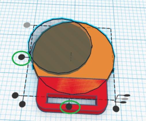
Select the Align tool located in the top right toolbar.
When the dots appear, click the center dots of both the left and bottom sides.
Pull Hole Through Box


Hover over the view cube in the top left corner to display arrows around the cube. Select the bottom arrow to convert the view to Front. If the arrows are not available, select the House icon first to change the perspective and then front view.
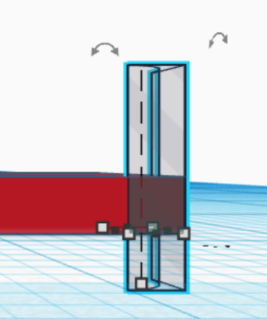
Select your hole shape, then select the black arrow (which may appear above or below the shape), and drag downward until it is -1 mm below the workplace surface. A white box will appear to the right that will display the distance from the bottom of the shape in relation to the ground plane.
Group to Create Hole
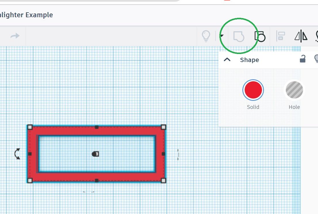
Hover over the view cube and select the Top arrow to return to top view.
Highlight both objects again.
Select the Group icon in top left toolbar.
Create Handle


Drag a second box shape onto the workplane below your reading window.
Adjust the dimensions to: length- 50 mm, width- 10 mm, height- 2 mm.
Select the box and move it up or down until second box is just barely overlapping the bottom of the first box.
Add Fillet
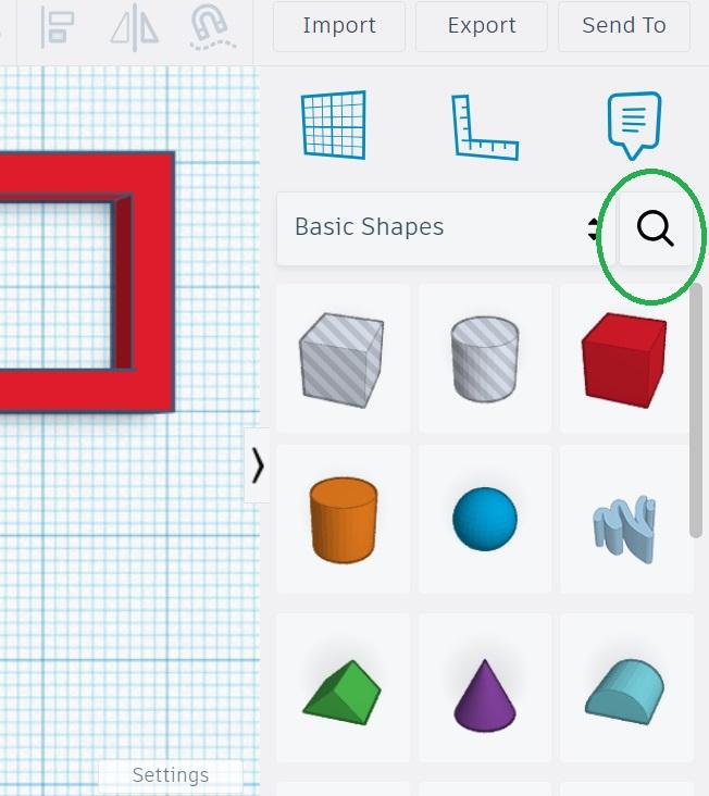


Select the Search icon in the Shapes toolbar and type MetaFillet. When the shape appears, click the star to save the shape as a Favorite.
Drag the shape onto the workplane near the upper left corner of your window box. Convert it to a hole by select the Hole option in the form. Adjust the radius to 2.
Round First Corner of Window Box

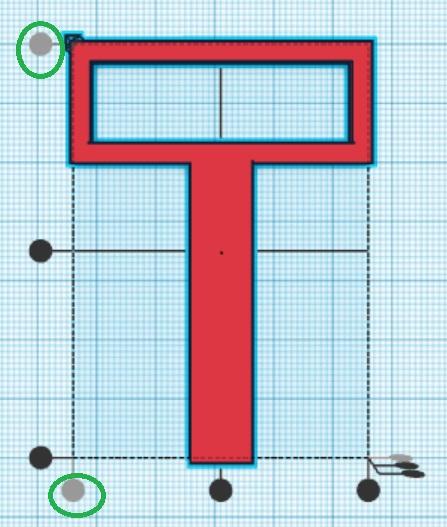
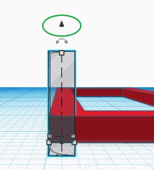
Select the rotate icon and rotate the fillet 90 degrees by clicking and dragging or typing 90 in the text box.
Select both the fillet and reading window shapes by clicking the fillet and holding shift as you click the reading window.
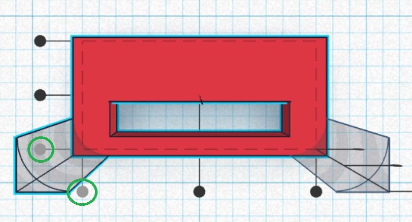
Now align the fillet to the window box by selecting align and then selecting the left, top dot and the bottom, left dot. Click off both objects.
Select Left View, then select the fillet shape. Click and drag the black area down until the shape is through the ground plane at least -1 mm.
Round Second Corner


Return to Top view and rotate your plane by holding your right mouse click while rotating.
Select the first fillet and then click Duplicate and Repeat in the top left toolbar. Next select Mirror in the top right toolbar. When the black arrows appear select the vertical arrow to flip the shape vertically.
Highlight the fillet and the reading window. Select Align and then click the two dots in the bottom left corner. Click off both objects.
Round Third Corner

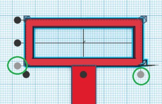
Select your new, second fillet. Click Duplicate and Repeat. Mirror the shape using the horizontal arrow. Select the third fillet and reading window, click align, and align using the left, bottom dot and the bottom, right dot. Click off both objects.
Round Fourth Corner
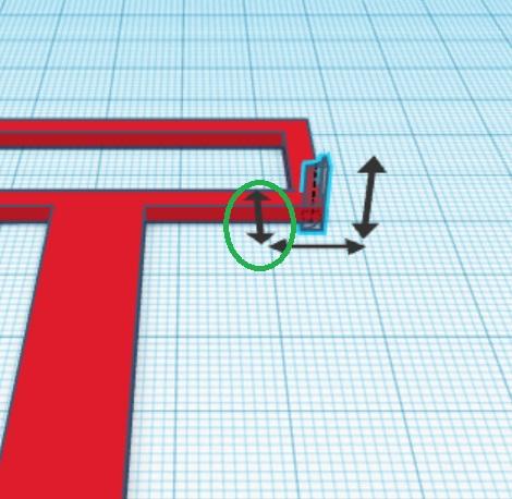

Select your new, third fillet. Duplicate and repeat. Mirror the shape using the vertical arrow. Highlight the fillet and the reading window, click Align, and align using the left, top dot and the bottom, right dot.
Round Fifth Corner

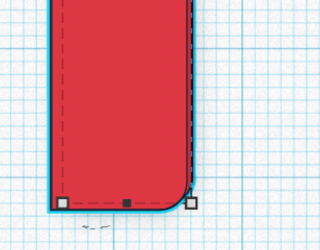
Select your third fillet. Duplicate and repeat. Select your new fillet and the handle. Select align and align using the left, bottom dot and the bottom, right dot. Click Group. Click off both objects.
Round Sixth Corner
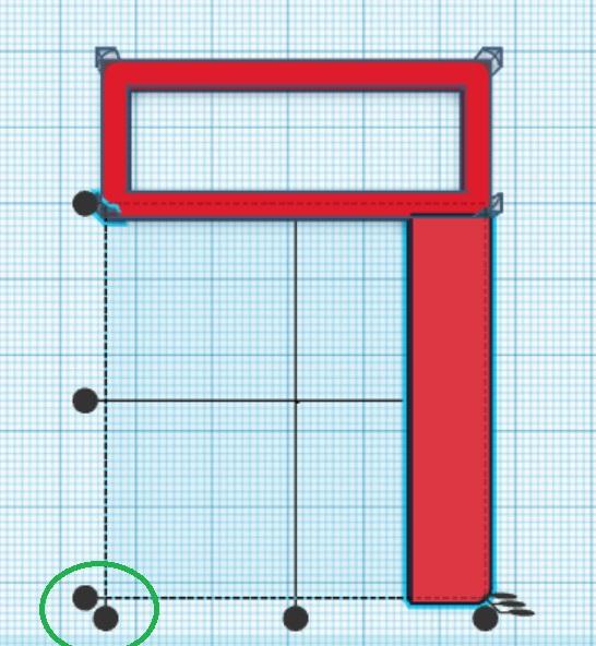
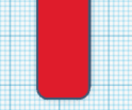
Select your second fillet. Duplicate and repeat. Select your new fillet and the handle. Align using the two bottom, left dots. Click Group.
Group Reading Window and Fillets

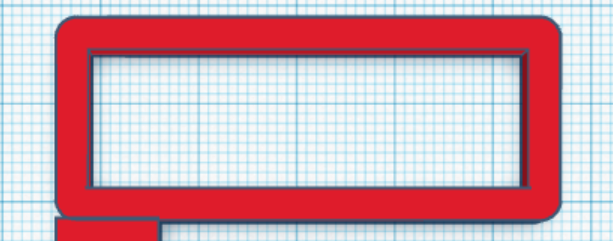
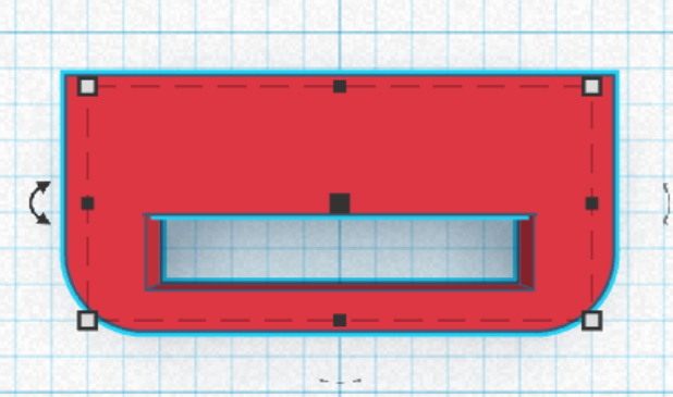
Select your first four fillets and the reading window (do not select the handle). Click Group.
Align and Group Reading Window and Handle


Highlight your Reading Window and Handle. Align using the bottom, center dot. Click Group. Click off objects.
Create Ring Base


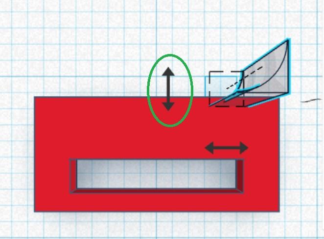

Place a new box on the workplane. Adjust size to: length- 6.5 mm, width- 14 mm, height- 2 mm.
Add a box hole over the top of the new box. Adjust size to: length- 2 mm, width- 10 mm, height- 4 mm. Adjust to front view, select the hole, drag the black arrow down until the hole is at least 1 mm below the workplane.
Return to top view. Drag the hole inside the box until there is just a small border along the bottom. Select both objects, align using the bottom, center dot, and finally group.
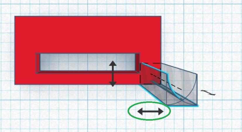
Go to your Favorite shapes and add metafillet. Adjust radius to 2 mm. Convert to hole. Mirror the fillet vertically. Align with the box using the left, bottom dot and bottom, right dot.
Select just the fillet. Duplicate and repeat. Mirror horizontally. Select the new fillet and the box. Align using the two bottom, left dots.
Select all three objects and group.
Create Ring



Using a caliper, measure the diameter of the finger you want your ring to fit between the first and second joint.
Return to basic shapes and add cylinder to workplane near the Ring Base.
Click the bottom, right node (a white square), and adjust the measurements of each side to your finger size plus 4 mm. For example, if your finger measured 14 mm your cylinder sides will be 18 mm.
Select the top, white node and adjust the height to 2 mm.
Drag the cylinder onto the Ring Base until the bottom of the cynlinder meets the hole. Do not allow the cylinder to overlap the hole.
Add a cylinder hole to the workplane over the cylinder. Adjust the measurement of each side to equal your finger size. Pull the hole down until it is at least 1 mm below the workplane.
Align the hole to the cylinder using both center dots. Group.
Select the Ring and the Ring Base. Align using bottom, center dot.
Select the Ring and ungroup. Now select all three objects and Group.
Create Ring Opening


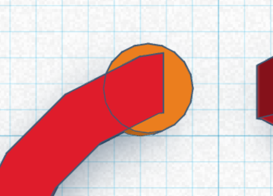


Add a box hole to the workplane. Adjust size to: length- 3 mm, width- 4 mm, height- 4 mm.
Drag the onto the top of the ring. Align with the ring using the left, top dot and bottom, center dot. Drag the hole down until it is at least 1 mm below the workplane.
Select both objects and group.
Add a cylinder to the workplane near your new opening. Adjust size to 3 mm on each side and 2 mm for the height.
Drag the cylinder to the tip of one side of opening. Duplicate and repeat. Using keyboard arrow, move the new circle to the other tip.
Highlight all three objects and Group.
Group for Printing

Now select your Ring and move it as close as you can to the wand without overlapping.
Export for 3D Printing
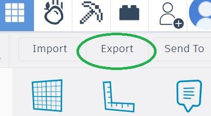

Select Export and then .STL.
Now you can go to your 3D printer slicer and upload your 3D model.