Tinkercad Robotics for School: Laser-cut Walking Machine!
by M.C. Langer in Teachers > 8
16000 Views, 148 Favorites, 0 Comments
Tinkercad Robotics for School: Laser-cut Walking Machine!


Hello and welcome to a new episode of my "Tinkercad Robotics for School" series! Usually I dedicate this space to 3D printing projects. However, a few months ago I had access to a Snapmaker desktop laser cutter for the first time. My first idea for a project? A basic walking robot, that could be built at schools.
When an educational center wants to purchase equipment for its makerspace, the first gadgets to come to mind are 3D printers. But what about laser cutters? Each type of machine has its advantages and disadvantages. 3D Printers (Additive Manufacturing) can create 3D models with more complex shapes and less waste of material, but the printing process can take hours and even, days; and 3D printing materials are more expensive and harder to find. Laser cutters (Subtractive Manufacturing) are a faster method, achieving more immediate results (even in minutes); and it can use cheaper and easy-to-get materials (wood, acrylic, leather, cardboard). However, complexity of models may be more limited than the ones achieved with 3D printing, professional machines may require more workspace to operate, more material may be wasted, and don't forget the basic considerations of eyes protection and fire prevention.
What is the best option? That depends on the kind of projects you are developing in your classroom. The ideal scenario is to have both a laser cutter and a 3D Printer in your makerspace. But consider this: if you want to teach a lesson in CAD and Robotics, you have 16 students, you want everybody to take a robot home but you only have two days to complete the task; with the time it takes to 3D print the parts for one single robot, your laser cutter can create robot pieces ready to assemble for 16 happy kids.
In today’s lesson, we will use Tinkercad to design a walking machine, and then, we will bring it to life using the Laser mode of the Snapmaker CNC Machine.
Fun Facts
- The world “Laser” is an acronym for "Light Amplification by Stimulated Emission of Radiation". Since its invention during 1960, they have been used in thousands of different applications, including consumer electronics, information technology, communication, science, medicine, industry, space exploration, law enforcement, entertainment, and the military.
- Boston Dynamics is an American engineering and robotics design company founded in 1992. They are famous for their 4-legged and 2-legged walking robots Spot, Handle and Atlas. They can walk in any terrain, keep balance in different situations and even, stand up by themselves after falling!
Definitions
- CAD (Computer-Aided Design): the use of computer technology to design an object.
- CAM (Computer-Aided Manufacturing): the use of computer technology to control machine tools to create objects.
- CNC (Computer Numerical Control): automated control of machining tools (such as laser cutters, drills, lathes, mills, routers and 3D printers) by means of a computer. A CNC machine automatically processes a piece of material (metal, plastic, wood, ceramic) by following coded instructions created in a computer.
- Laser Cutter: CNC machine that uses a high-power laser beam to melt, burn, or vaporize away materials, leaving an edge with a high-quality surface finish.
- Robot: machine that can perform a task by automatic or semi-automatic controls.
Supplies

EQUIPMENT AND MATERIALS:
- 1 CNC Snapmaker Original, with 1600mW Laser Cutting Module (or any other available Laser Cutter)
- 1 laptop with Wi-Fi connection.
- 1 Laser Safety Goggles
- 5 Wood tablets of 120mm x 120mm x 3.15mm
- 1 hobby gearbox (yellow motor)
- 1 AA Batteries holder for two batteries
- 2 AA Batteries
- 1 PVA glue for wood
- 2 metal washers
- 1 rubber band
- 4 small binder clips
- 1 Vernier caliper
- 1 Ruler
- OPTIONAL: cutter, small abrasive file, sandpaper, color markers, super-glue (cyanoacrylate).
SOFTWARE:
- Tinkercad (www.tinkercad.com)
- Snapmaker Luban and CH340 Driver for Windows (https://snapmaker.com/product/snapmaker-original/downloads)
- Inkscape (https://inkscape.org/). I am using the 1.1 version for Windows. However, new versions are already available.
Pre-Lesson


- Download the Snapmaker and Inkscape programs to the classroom computers and get acquainted with the software.
- Check the Snapmaker User Manual. Review the operation instructions and safety measures.
- Connect, test, and perform all setup calibrations in the Snapmaker CNC machine and software before the lesson. To save time and achieve a good cutting, it is especially important to know how to achieve the right calibration on each Snapmakers, particularly in the Z-axis. More about this topic later.
- Create a sample of this walking robot, so you can train yourself in this project and show students what they will be designing and building.
- Prepare the materials.
- Verify the dimensions of each wooden tablet. Check the thickness using the caliper. This lesson will work with 3.15mm of thickness, and it is very important to keep this value in mind. In case your wooden tablets have a different thickness, use that value instead during the design, and consider it during the cutting process.
Side Panel and Gearbox


- Open Tinkercad. Students must bring a Box from the Basic Shapes library. For the moment, this box will be of 50mm (length) x 80mm (width). Now, there will be an extremely critical dimension to consider during the rest of the lesson: the thickness of the wooden tablet (in this case, it will become the height of the box). Explain students that this walking robot will be assembled as a Lego, and to achieve that, the holes of each piece must be as wide as the thickness of the connecting parts; and the best way to have an accurate measurement of this thickness is using a caliper. If your wooden tablet has a different thickness (example: 3.80mm), then use that value instead of 3.15 every time we use that dimension.
- Activate the Ruler Tool (placed between the Workplane and the Notes tools) and place it in the bottom-left corner of the box.
- Bring a Hobby Gearmotor from the Circuits/Components Library and place it on the left part of the box.
- Change to Orthographic View. Most of this lesson will be using Orthographic. Also, change the Snap Grid from 1.0mm to 0.1mm. Go to the View Cube and select Top View. Using CTRL + Down Arrow Key, bring the Gearmotor down, until the yellow box is over the red box.
- Change to Top View. Place the Gearmotor 6.00mm away from the left border of the box, and 8.00 mm from the lower border.
- Bring a Box Hole to the left of the Gearmotor. The dimensions are 20mm (length) x 3.15mm (width, equal to wooden tablet thickness). It must be placed 2.30mm away from the left border of the box, and 20.00 mm from the lower border.
- Duplicate that hole box and place it on the other side of the Gearmotor. That will be like 30mm from the left border of the box.
- Check that the Gearmotor is exactly between both holes, without overlapping any of them.
Place the Battery Holder


- Bring a 68mm (length) x 35mm (width) x 22.30mm (height) box and change it to black color. It will represent the space for the AA Battery Holer. Place it after the last hole box we created. If you check the real Gearmotor and AA Battery Holder, you will realize that the have more or less the same thickness. So go to Front View and check that the same is happening in Tinkercad.
- Check that the lower part of the Battery Holder is aligned with the lower part of the Gearmotor. In this example, the lower part of the Battery Holder is located 34.10mm from the left edge of the red box, and 8.10mm from the lower edge.
- Duplicate again the hole and place it after the Battery Holder (70.30mm from the left edge of the red box, 20mm from the lower edge.)
- Using the middle handle from the right edge, reduce the width of the red box from 80mm to 76mm.
- Select the last hole we created (right side of the battery holder) and reduce its length to 10mm. Also, move it closer to the upper edge of the red box, until it is 70.30mm away from the left border of the red box.
- Duplicate (CTRL-D) that hole and bring it down, placing it 19.20mm away from the lower edge.
- Duplicate the hole box that is between the gearmotor and the battery holder and bring it down.
- Now, rotate it 90 degrees.
- Move that hole box to the left and place it directly under the lower part of the gearmotor. That must be 8mm from the left border, and 4.02mm from the lower border of the red box.
- Duplicate the hole box (CTRL-D), and move the duplicate to the right, until it is placed under the battery holder (45mm from the left border of the red box.)
Front Panel


- Bring a Box of 42.19mm (l) x 19mm (w), to create the Front Panel.
- Create a duplicate of the hole (20mm x 3.15mm) located near the Gearbox.
- Move that duplicate next to the new box created in the first step.
- Transform the hole into a solid.
- Change the height of that new solid shape to 3.15mm.
- Duplicate this box, and place it on the opposite side of the first box. It must look like a cross.
- Select and group all these new three shapes.
Bottom Panel


- Bring a Box of 19mm (L) x 76mm (W), to create the Bottom Panel.
- Create a duplicate of the two holes (20mm x 3.15mm) located under the Gearbox.
- Move that duplicate next to the new box created in the first step.
- Transform the holes into solids.
- Change the height of those new solid shapes to 3.15mm.
- Duplicate these boxes, and place them on the opposite side of the first box. It must look like a double cross.
- Select and group all these new three shapes.
Back Panel


- Bring a Box of 42.19mm (L) x 19mm (W), to create the Back Panel.
- Create a duplicate of the two holes of 10mm (L) x 3.15mm(W) located at the right side of the Battery Holder.
- Bring the duplicate holes at the left side of the first box, and make them Solid.
- Take the duplicate hole located in the lower part, and increase its width to 20mm.
- Select the small box on top and this new 20mm (W) box. Duplicate them, move them to the opposite side of the box, and mirror them.
- Change the height of those new solid shapes to 3.15mm.
- Select and group these five boxes, creating a shape that looks like an airplane.
Washers


- Bring a cylinder of 20mm diameter X 3.15mm height.
- Place a Hole Box of 10mm (L) X 3.15mm (W), in the center of the cylinder. Use the Align Tool for this operation.
- Select both shapes and group.
Last Adjustments for the Side Panel


- Hide or delete the Battery Holder.
- Transform the Gearbox into a Hole; select it and the Side Panel, and group them.
- Check the circular partial holes on the Side Panel, left by the protrusions of the Gearbox. Place slightly bigger cylinders on them, and group them with the Side Panel, so the holes will become complete. This will allow the real Gearbox to fit perfectly on the Side Panel.
- At the end, you must have five shapes: Front Panel, Side Panel, Back Panel, Bottom Panel, and Washer.
Exporting the Body Components


- Check that all the shapes are exactly over the Workplane (select one by one, and click the "D" key.)
- Now, select all the shapes, and take them down 0.1mm. Why? Because Tinkercad will create SVG profiles from the objects intersecting the Workplane.
- Go to "Export".
- Select ".SVG" in the Lasercutting area.
- Save each piece as a SVG document.
NOTE: I recommend you to check this Tinkercad Blog link, explaining more about SVG files:
https://www.tinkercad.com/blog/import-and-export-svg-files-tinkercad
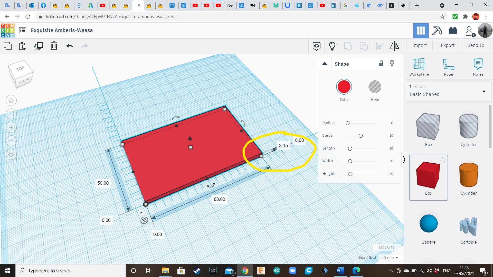

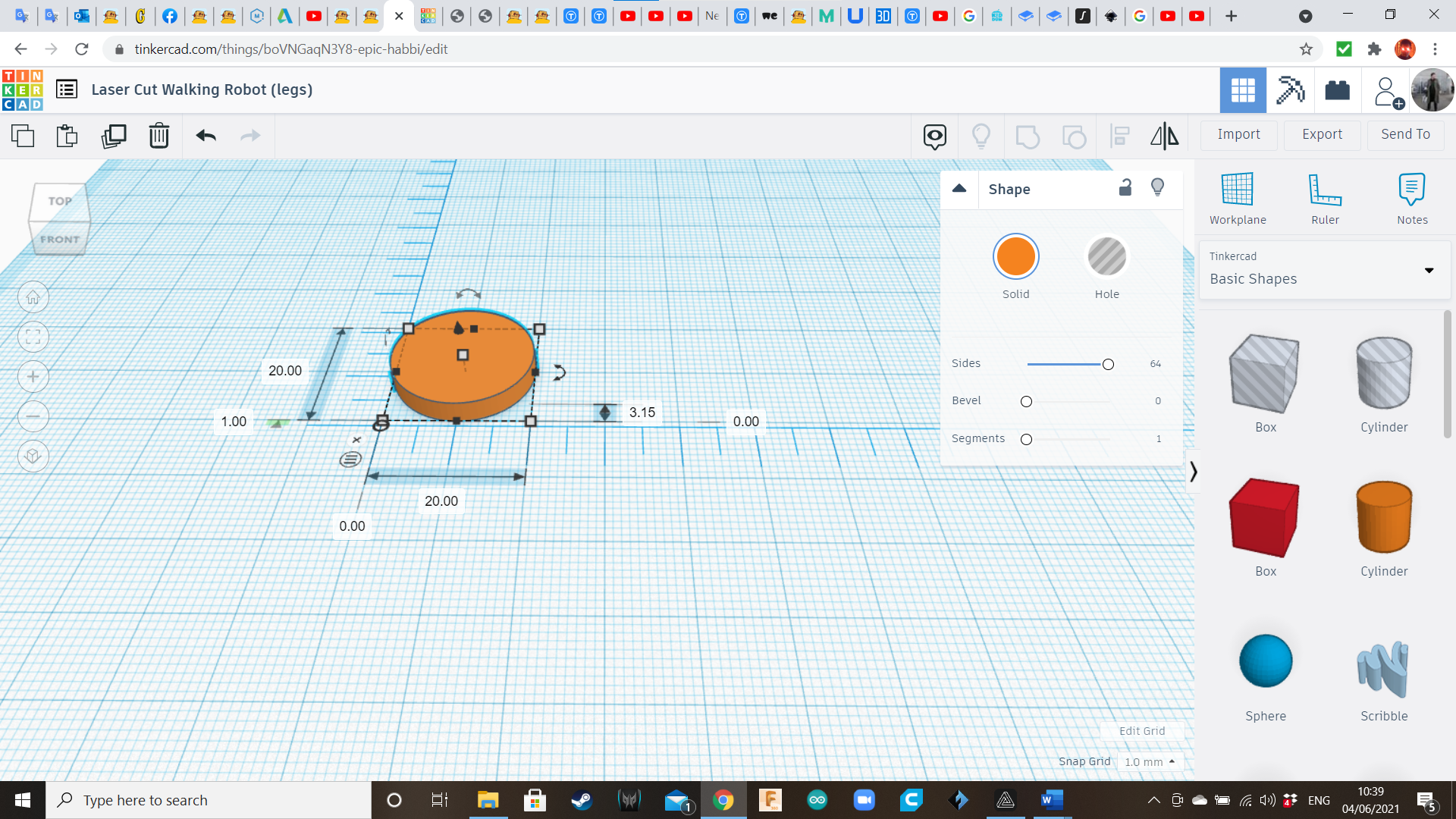


- Let's remember that the height (H) of the following solids is also 3.15mm (real-life thickness of our wooden tablet.)
- Bring a cylinder of 20mm diameter.
- Align (by eye) the center of the cylinder to the axle of the Gearbox.
- Transform the Gearbox into a hole, and group both shapes.
- Create a Box hole of 3.15mm (L) x 5mm (W). Duplicate this hole. Place one of the copies between the cylinder's center and the border. Select and group. We will call this shape "Wheel".
- Take the second hole box, and place it in the center of a cylinder of 10 mm diameter. Select and Group both of them. Duplicate this new shape (from now, we will call them "Locks")
- Create a Box of 15.75mm (L) x 5mm (W). We will call this shape "Axle". It will fit tightly inside the side hole of the Wheel, and the center hole of the Locks
Front Leg


- Bring a Box of 80 mm (L) x 15mm (W), to create the Front Leg.
- Create two holes: one cylinder of 6mm diameter, distant 45.20mm (more or less) from the bottom border; and a box of 3.15mm (L) x 5mm (W), on top.
- Select these three shapes, and group.
Back Leg


- Bring a Box of 50 mm (L) x 15mm (W), to create the Back Leg.
- Bring a cylinder of 20mm diameter, and place between the center and the top end of the box.
- Bring a cylinder of 11mm diameter, and place it in the center of the bigger cylinder. Use Align tool to verify.
- Select these three shapes, and group.
Transmission Rod


- Bring a Box of 40 mm (L) x 7 mm (W), to create the transmission to connect the Back Leg, to the front one.
- Rotate it 45 degrees.
- At the end of the rod, add a cylinder of 15 mm diameter.
- Add a cylinder of 6 mm diameter, aligned to the center of the previous cylinder.
- Select all the shapes, and group them to create a single Back Leg with transmission rod.
Exporting the Legs Components


Follow the same procedure from Step 9.
Preparing the Parts for Lasercutting (Inkscape)


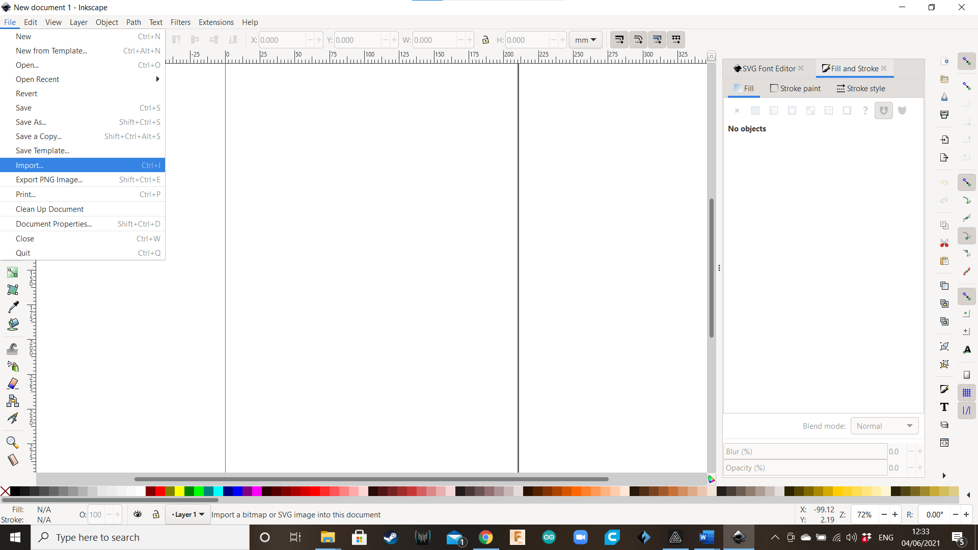


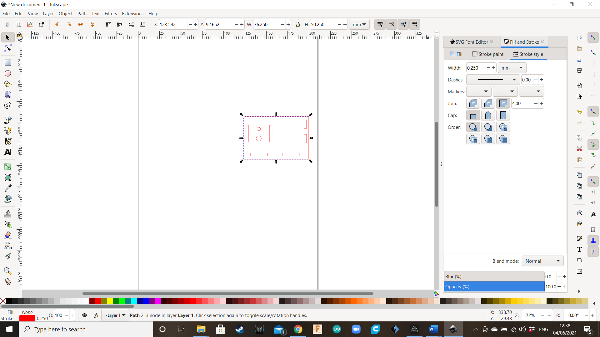


- In theory, the parts are ready for cutting. However, when I tried to import them to the Snapmaker Luban app, they were nowhere in sight. In this case, Tinkercad shapes had a very thin line, and they will be invisible when you bring them to the Snapmaker Luban app. To solve this problem, we will use a tool named Inkscape. Click on the icon and open Inkscape. A small window will appear. Click on “New Document”.
- We will need to deploy a special window to modify our shapes. Go to the top bar menu and click on “Object”, then click on “Fill and Stroke”.
- Let’s start importing our shapes. Go to “File” and select the option “Import”.
- Choose one of the shapes. In this case, we will select the Side Panels and the Front Panels
- A window named “SVG Input” will appear. Select the first option “Include SVG image as editable…” and go directly to “OK.”
- As expected, the Side and Front Panels are not visible, and you can only see a selection square. So, go to the “Fill and Stroke” area (right area of the screen).
- Go to “Stroke Style” and click on “Width”. Change the value from 0.004mm to 0.250mm. Now your shapes are visible!
- Click on the shape and bring it to the top left corner of the page.
- Go to “Edit” on the top bar and click on “Resize Page to Selection”. This is necessary so the program only exports the required area and not all the page. After doing this, the page will be reduced to a square around the selected shapes.
- Go to “File” and click on “Save”.
- Save the file. You can create a new folder named “SVG Visible” and name the file “Double Side Test” or some other name; or simply, overwrite the original file, but be careful to control the files you already improved.
- Let’s import the next file. Go to “File” and click “New”.
- Follow the previous instructions to import the Top Panel and modify it. At the end, name it “Top Ready”.
- When you finish, click again “File/New”, and bring the remaining pieces of the robot. You can import several files and arrange them in a way that all of them may fit in a single wooden tablet. Select each piece and move it using the arrow keys. Use the ruler the confirm that they do not exceed the size of the wooden tablet (120mm x 120mm; but is better to leave a safety margin).
SVG Body
Here you will find the SVG files for the body.
SVG Legs
Here you will find the SVG files for the legs.
Snapmaker


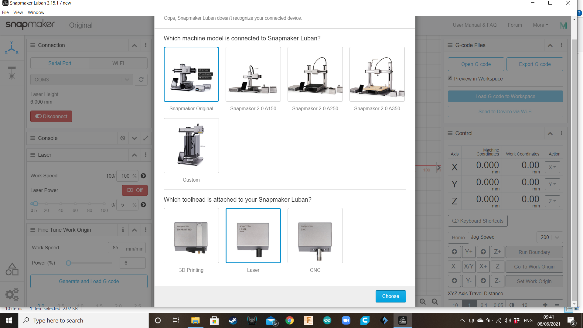
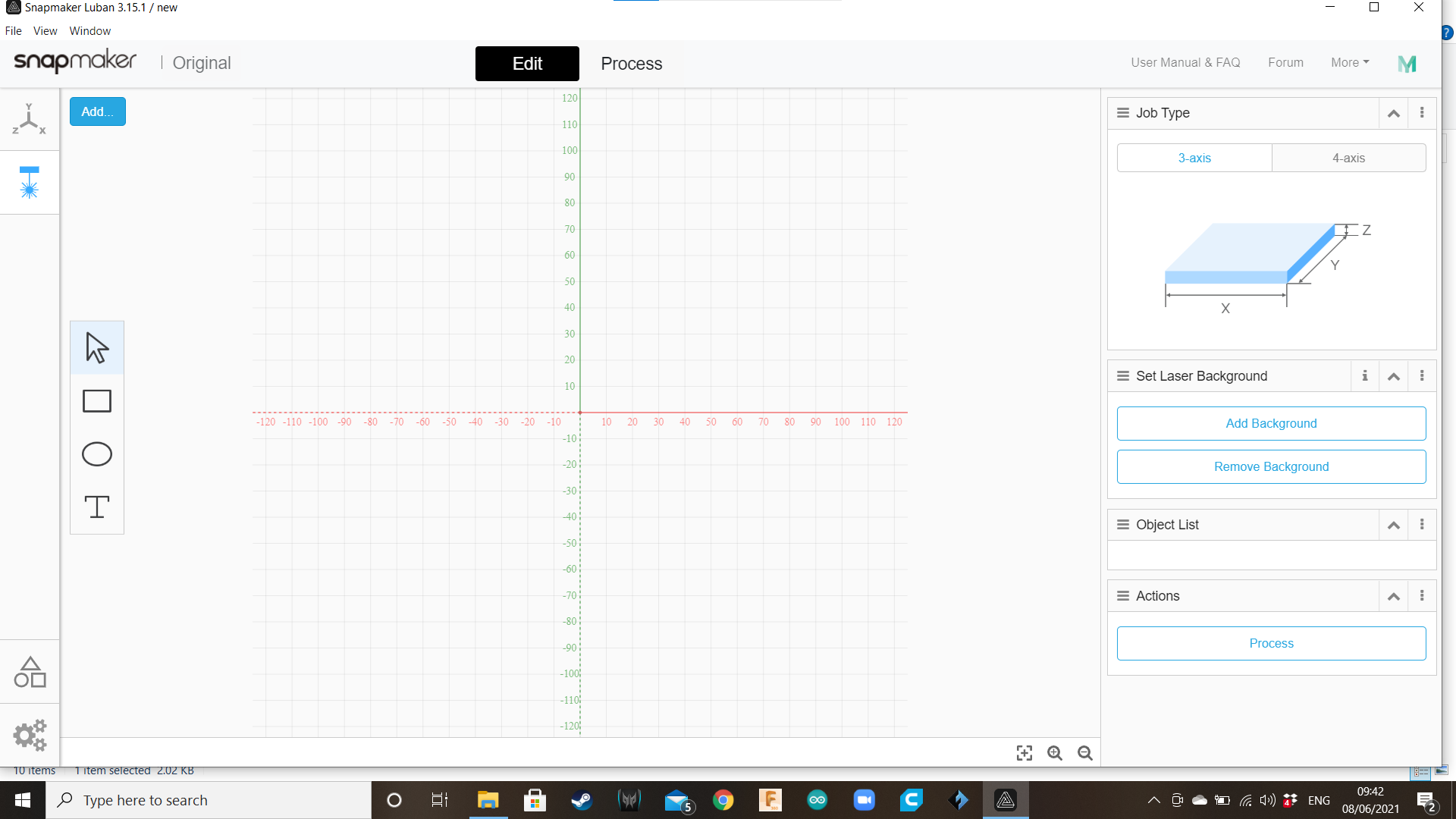


1.Now that our parts are visible and in a proper distribution, let’s lasercut with the CNC Snampmaker. Open the Snapmaker Luban application.
2.For safety and quality of the lesson, the teacher must be already acquainted with the Snapmaker basic operation. In case of doubt, please refer to the operations manual that comes with the Snapmaker. However, let’s remember the basic steps. In the Snapmaker’s application lobby you will find a left toolbar with four options (Workspace, 3D Printing, Laser and CNC Engraver). Go to “Workspace” (on top of the left bar, the symbol of the X,Y,Z coordinates.)
3.Turn on the CNC Snapmaker and connect the cable to one of the USB port. In the “Connection” window, click the Refresh icon and select the COM where the CNC Snapmaker is connected.
4.A window will appear, asking to confirm the machine you are using (Snapmaker Original) and the attached Toolhead (Laser). Then click “Choose”.
5.If the connection was successful, the four options of the left toolbar will be reduced to only two (Workspace and Laser), and you will be in the “Edit” screen of the “Laser” option. Click “Add”.
6.Choose the first SVG ready file (in this case, “Bottom Ready”). Probably it will appear on the center of the cartesian plane, so move it to the top right quadrant. Check that the shape is not surpassing the dimensions of the wooden tablet (it’s 120mm x 120mm, but consider 110mm x 110mm to leave some available space for the binder clips to attach the wooden tablet to the platform). This file will be processed as a Vector. Then, click “Process” (right toolbar).
7.Now the shape is in the “Process” screen, where you will add a toolpath. A toolpath is the program that controls the speed and intensity of the laser, and the number of times it will travel over the shape. Click on the shape to select it. Then go to the right toolbar and click on “Create Toolpath”.
8.For the Toolpath, use the following configuration, then save:
- Name: Toolpath 1
- Fill: NO
- Jog Speed: 2000 mm/min
- Work Speed: 120mm/min
- Multi-pass: Yes
- Passes: 7
- Pass Depth: 0
- Fixed Power: Yes
- Power (%): 100
9.Now click on “Generate G-code”; and when it is ready, click on “Load G-code to workspace”.
WARNING: From now we will start operating the laser. Remind the kids that they must avoid eye or skin exposure to the laser beam and radiation, or they can get hurt or damage their eyes. Teacher and students must always wear the protective goggles (green color) when they are supervising the laser calibration and operation. Also, do not leave the CNC unattended when is working.
10.Now we will set the work origin in the CNC Snapmaker. The Work Origin is where the X and Y axis intersect in their 0 point, and it is where the cutting work will start. But first, we need to find the perfect focal distance in the Z Axis, between the laser head and the material to be cut. It is recommendable that teachers find this point when they practice before the lesson, to avoid delays and class management issues. Also, the focal distance in Z is critical to achieve a perfect cutting in just one attempt.
11.Place a wooden tablet on the CNC’s working area and fix it with binder clips. In the “Laser” option (right toolbar), select a low intensity (0.5) and turn the laser on. Then, using the Z+ and Z- controls, and the “XYZ Axis Travel Distance” control, find where the laser beam projects the smallest point (0.5mm). Use the “Calibration Card For Laser” that comes with the Snapmaker.
TIP: Once you have found the perfect focal distance of a Snapmaker, measure it with a ruler (from the cutting material to a reference point, like the Laser head label) and write it down. In this specific case, the perfect distance is 63mm. This will save you a lot of time for the next opportunities.
12.Using the X-, X+, Y+, Y- controls and the “XYZ Axis Travel Distance” control, bring the laser to the front left corner of the wooden tablet.
13.Click on “Set Work Origin”. From now, this will be the starting point of the cutting work.
14.Click on “Run Boundary”. The laser beam will do a preliminary travel showing the limits of the cutting work. In case the laser is burning out of the wooden tablet, it could mean that you need to move the Work Origin, place the wooden tablet in a better position or review your design.
15.If everything is ready, click on the “Run” icon (top of the cartesian plane). The laser will start engraving and cutting.
16.After finishing cutting this first shape, import another shape and repeat this whole procedure.
Taking the Parts Out of the Laser Cutter


When the work with the Laser Cutter is over, remove the pieces from their wooden tablets. Also, clean the holes.
For a more efficient work, we will start with the Body parts.
Assembling the Body


Bring one Side Panel, the Bottom Panel, the two Front Panels and the Back Panel. Assemble the box, without adding the other Side Panel. Use carpentry glue to stick the pieces together.
Inserting the Gearbox


Bring the gearbox, place it in its respective place, and then add the remaining Side Panel to complete the body.
Axles


Insert an axle in the Wheel, and another axle in the Front Leg.
Assembling the Leg Mechanism


Let's start with the left leg. Brink the Back Leg, and insert the axle of the front leg through its top hole. Then use a Lock piece to complete the mechanism.
Crank


Bring the Crank and two Locks. Place a Lock in the Crank's axle, then insert it through the available hole of the Front Leg, then add the second Lock.
Attaching the Left Leg Mechanism to the Body.


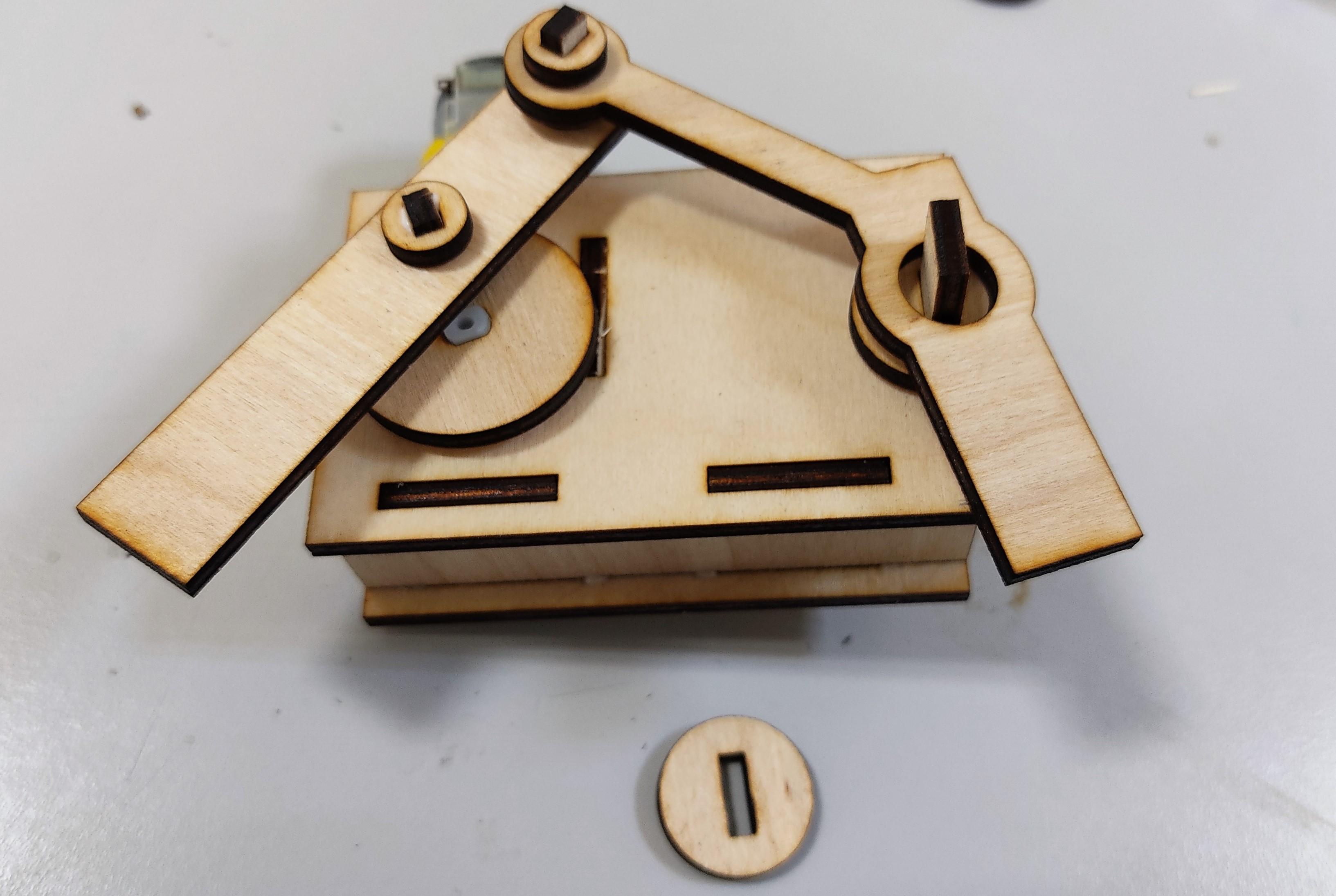


Place a Washer in the axle of the Back Panel. Bring the Left Leg Mechanism. Insert the axle of the gearbox in the center hole of the crank. Insert the Back Panel's axle through the biggest hole of the Back Leg, and lock with another Washer.
Now, repeat these last four steps, but with the Right Leg Mechanism parts.
Power


Bring the battery holder and insert two AA batteries, being careful of the polarity. Place the battery holder in the available spot in the robot. Connect the cables to the pins of the motor, and test the motion.
Test and Improvements


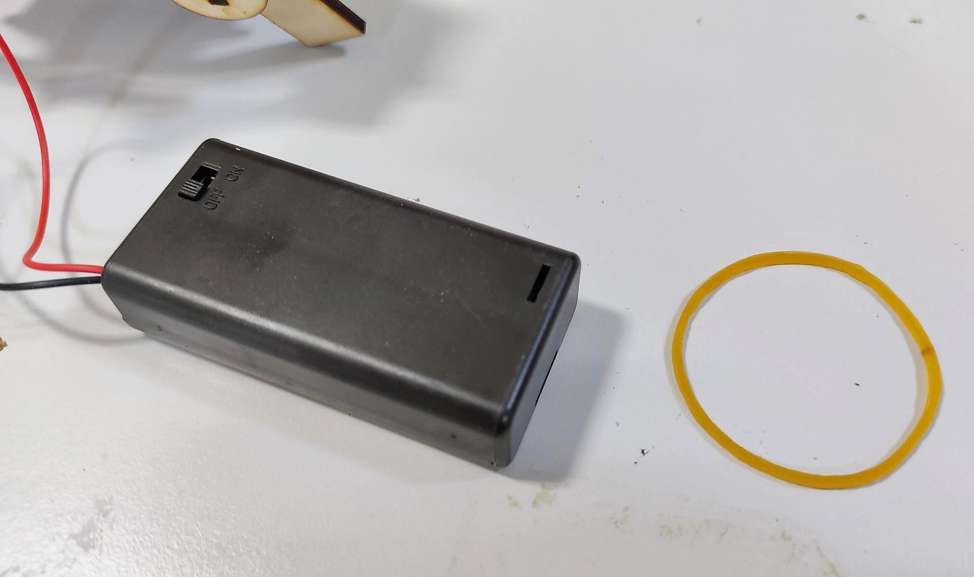
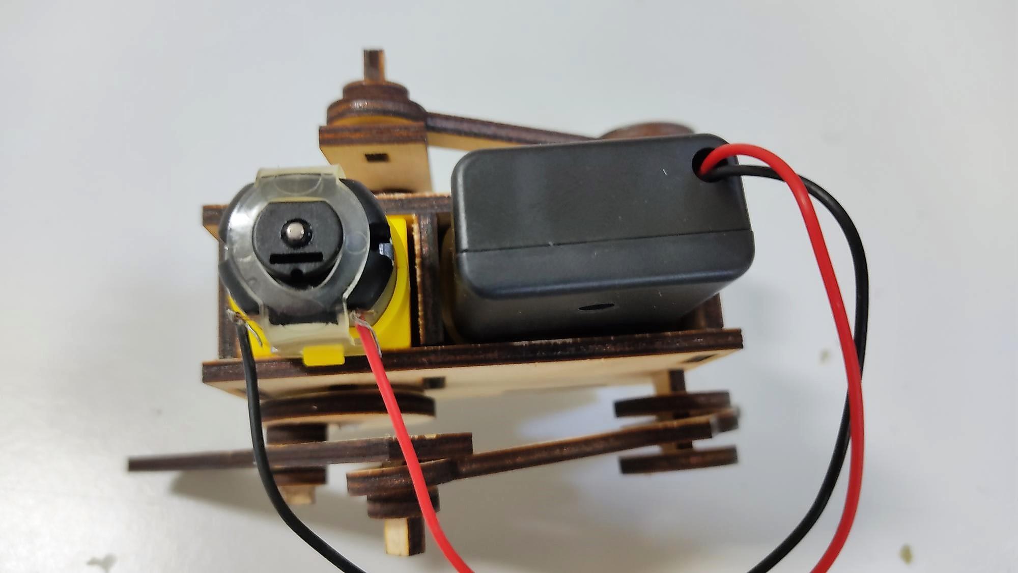
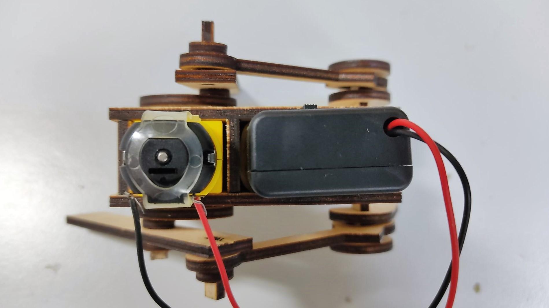

Place a metal washer in the axle of the gearbox, between the body and the crank. This will separate both wooden parts, reducing friction and allowing a more efficient motion.
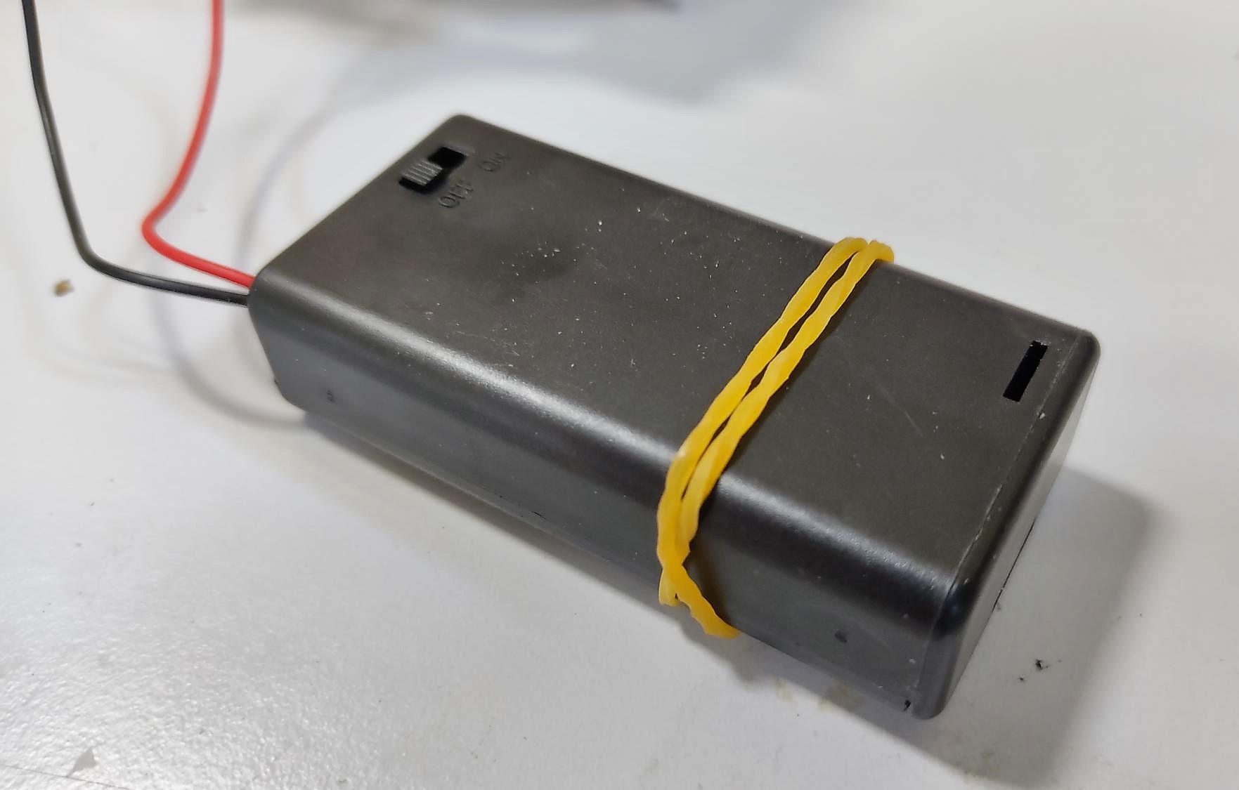
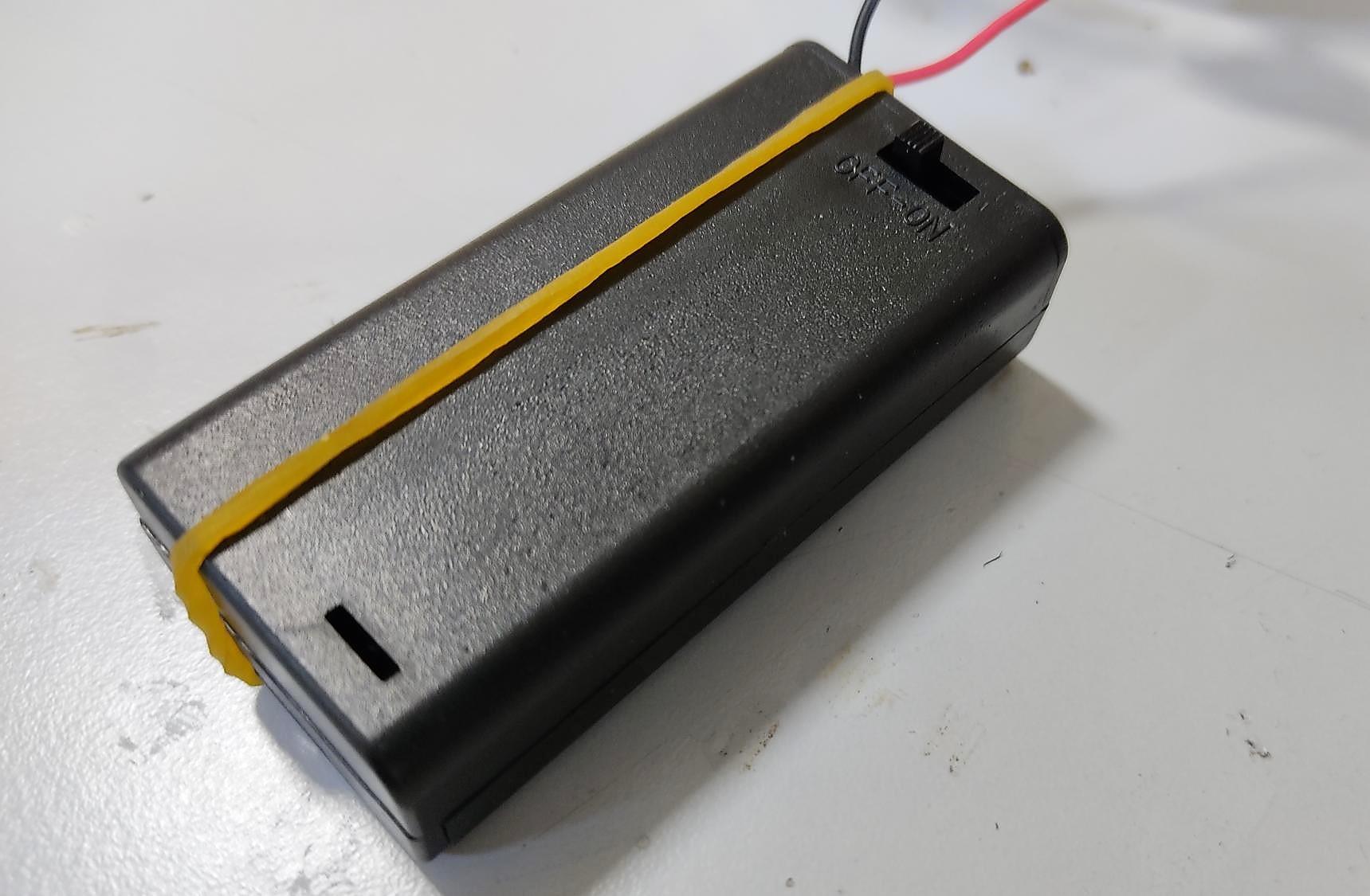
If the battery holder is falling constantly, place a rubber band around it, or add a little piece of double-sided tape in the cover, so it can stay inside the body using pressure and friction.
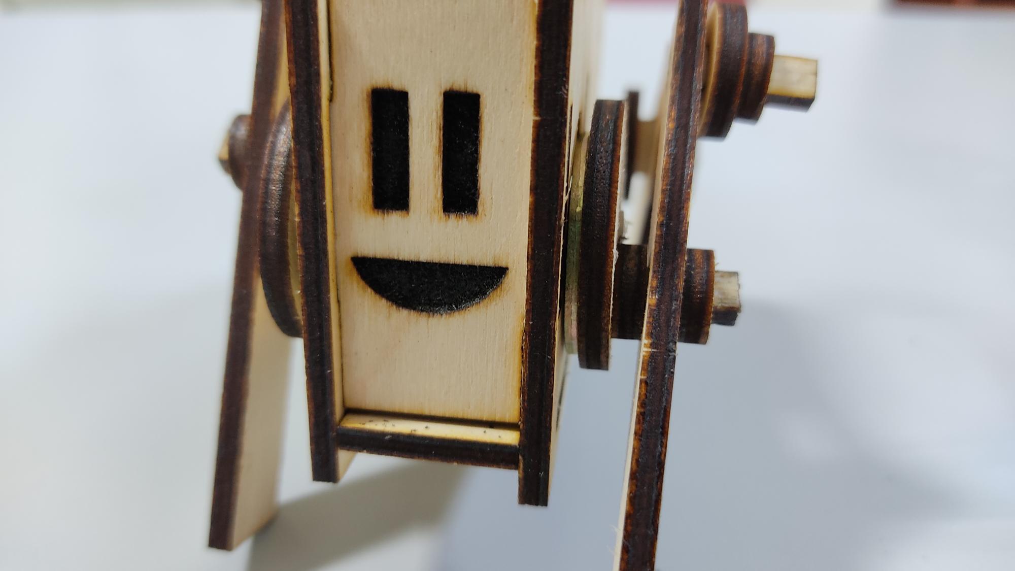
Add a face! Robots have the right to look happy!