Tiny Rechargeable LED Flashlight With USB Port
by TheLeftyMaker in Circuits > LEDs
720 Views, 5 Favorites, 0 Comments
Tiny Rechargeable LED Flashlight With USB Port
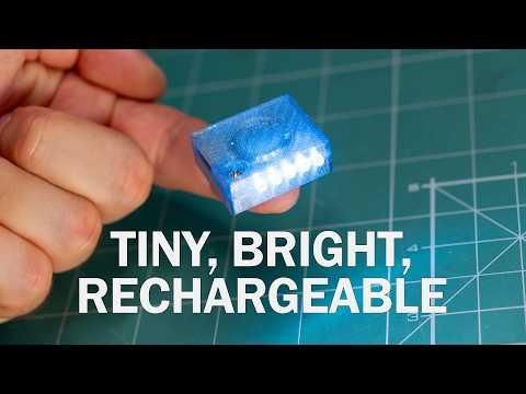
Making a flashlight seems like a trivial project, until you try to make it as small as possible. Shrinking any circuit design is a challenge that forces you to look at it from a different perspective – to consider details like how tall your USB port is or whether there's anything smaller than garden-variety, through-hole caps and resistors.
This project was inspired by YouTuber Gadget Industry, who built a truly tiny rechargeable flashlight – around 25 by 10 by 10 millimeters, by my estimates. My version isn't quite as small, but it lasts longer and is safer, in my opinion, which I'd say makes it more practical. Here are some of the key features of my design:
- Five 3mm white LEDs
- A 100mAh 3.7V rechargeable battery for at least an hour of runtime
- USB-C port for charging
- Two brightness levels
This project is not for absolute beginners. It involves a custom circuit board, two integrated circuits, a 3D-printed enclosure, and a Li-Po battery that can give you a bad time if not treated with respect. However, I don't expect anyone to replicate it as described. Instead, I hope the steps below contain enough advice, tips, and tricks for you to copy and incorporate into your own, hopefully much better designs. And if you want to copy or modify my flashlight anyway, the project files are available to download for free on my Patreon page.
Supplies
Here are the parts and tools I used for the project, along with links in case you want to order any:
Parts:
- 100mAh 3.7V rechargeable battery with protection - I got mine from AliExpress
- 5x 3mm LEDs - You can use any generic 3mm LEDs you like, as long as you know they're of good quality and have a clear lens. For my project, I used cold white LEDs from LCSC with a 20mA current rating and 30-degree beam angle for the lens. Model name XINGLIGHT XL-302UWC, LCSC part number C2895458
- Custom circuit board - this will be explained in detail below. If you plan to order one or make it yourself, you can use one of my free coupons for JLCPCB services.
- One pair M3 nut and bolt to hold the flashlight housing together.
Tools:
- A soldering iron: the one I use most of the time is a Miniware TS21 Amazon US / AliExpress
- Solder: I like Kester's rosin core solder ( Amazon link) but you can use any solder you like
- 3D printer: The 3D printer I currently use is an Elegoo Centauri Carbon 2 Combo Official store / Amazon US
- Filament: The blue one here is the Elegoo PETG Translucent Blue, but their regular PLA will work just fine, if not better
Disclaimer: some of these are affiliate links. This does not affect the price you pay, but I may earn a small commission, which helps me make more projects and videos. Thanks!
Selecting the Battery
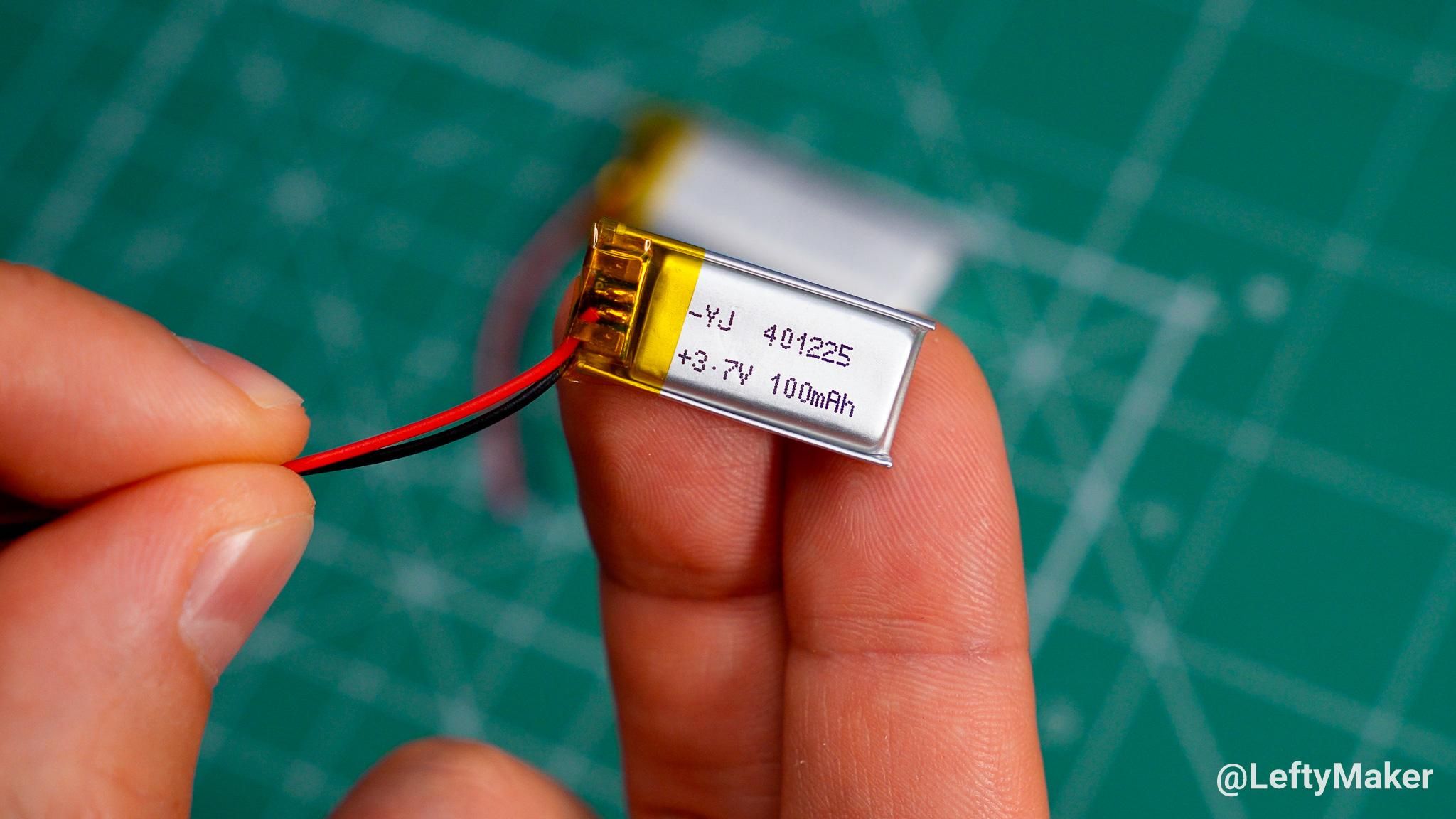
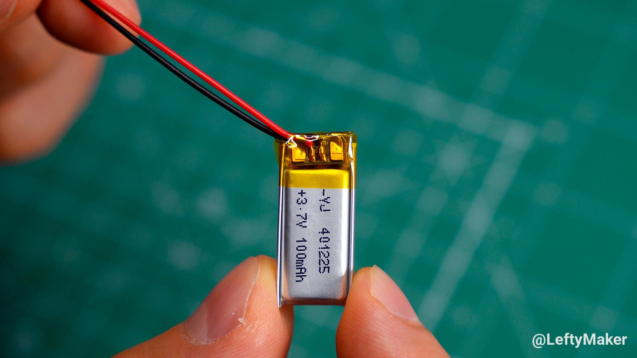
The battery is perhaps the most important part of a DIY rechargeable flashlight project. It directly affects three key aspects of the build:
- Runtime – how long the light stays on for
- Brightness – the peak light output depends on the current rating of the battery
- Enclosure Size – a bigger battery lasts longer and delivers more current, but takes up more space
That is why it was the first component that I picked and then build everything around it. After ordering a few different batteries to evaluate, I settled on a 100mA 3.7V Li-Po battery. It was indeed very small, yet bigger than the one used in the inspiration video (60mA). Also, it had a built-in protection module, which protects against overcharge, overdischarge, and short circuit.
Be aware that rechargeable lithium-ion batteries can be dangerous if overcharged, physically damaged, or exposed to extreme heat. Treat them with care and make sure you don't exceed the technical limits specified by the manufacturer. Do not trust specs listed on AliExpress or similar websites.
Selecting the LEDs
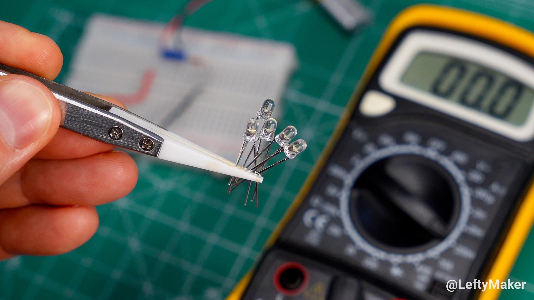
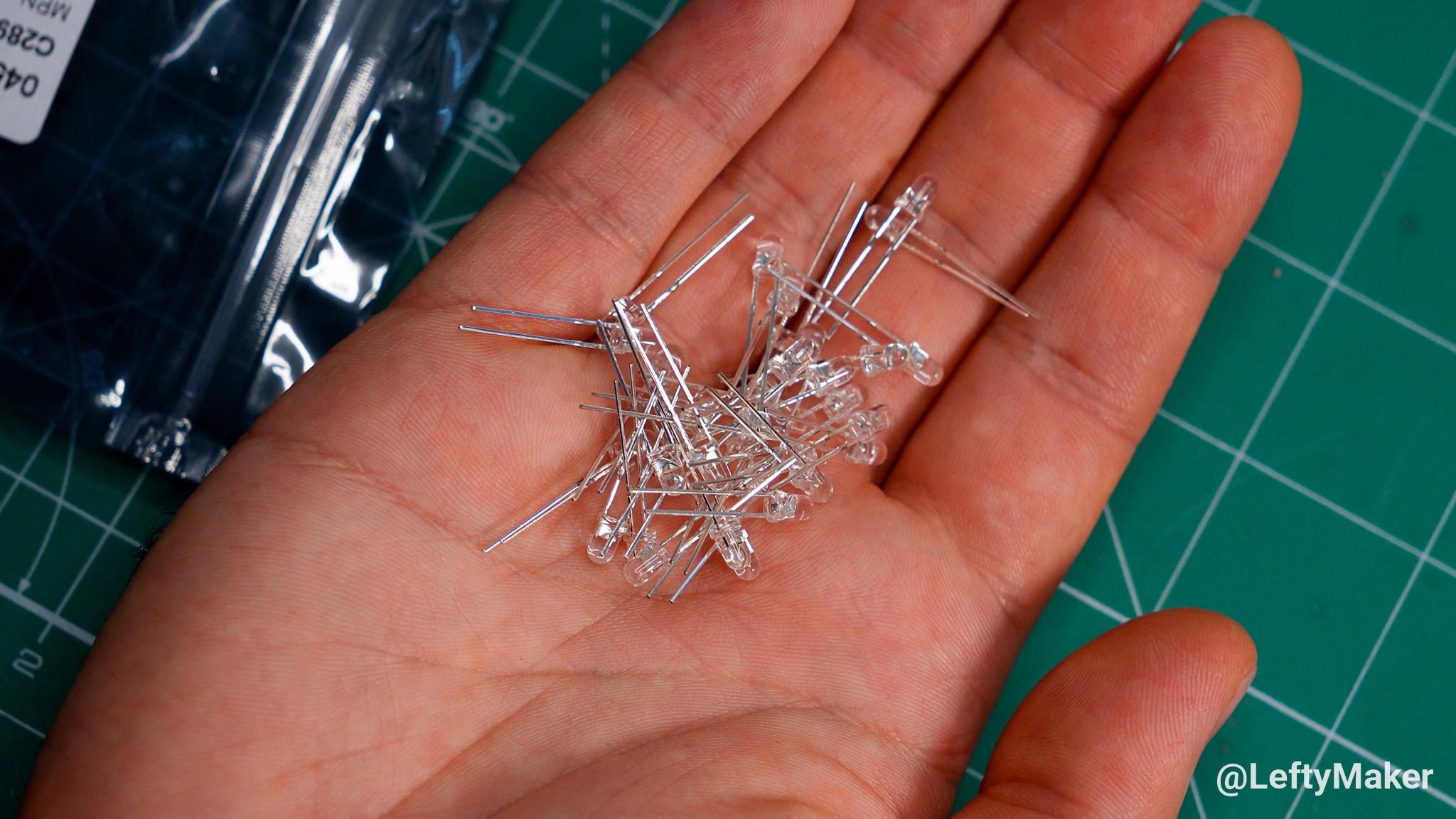
Picking the LEDs was tricky. The brightest and most efficient LEDs nowadays are not ideal for DIY hobbyists – they are SMD components, designed to be soldered on the surface of a circuit board or on a flexible strip. This makes it difficult to point them forward without resorting to hacks or to making a separate PCB just for the LED.
So instead, I decided to keep things simple and picked regular, 3mm LEDs. The flexible leads let me bend them in the direction I want, and the lens directs light forward, which is what you want in a flashlight.
How the Circuit Works
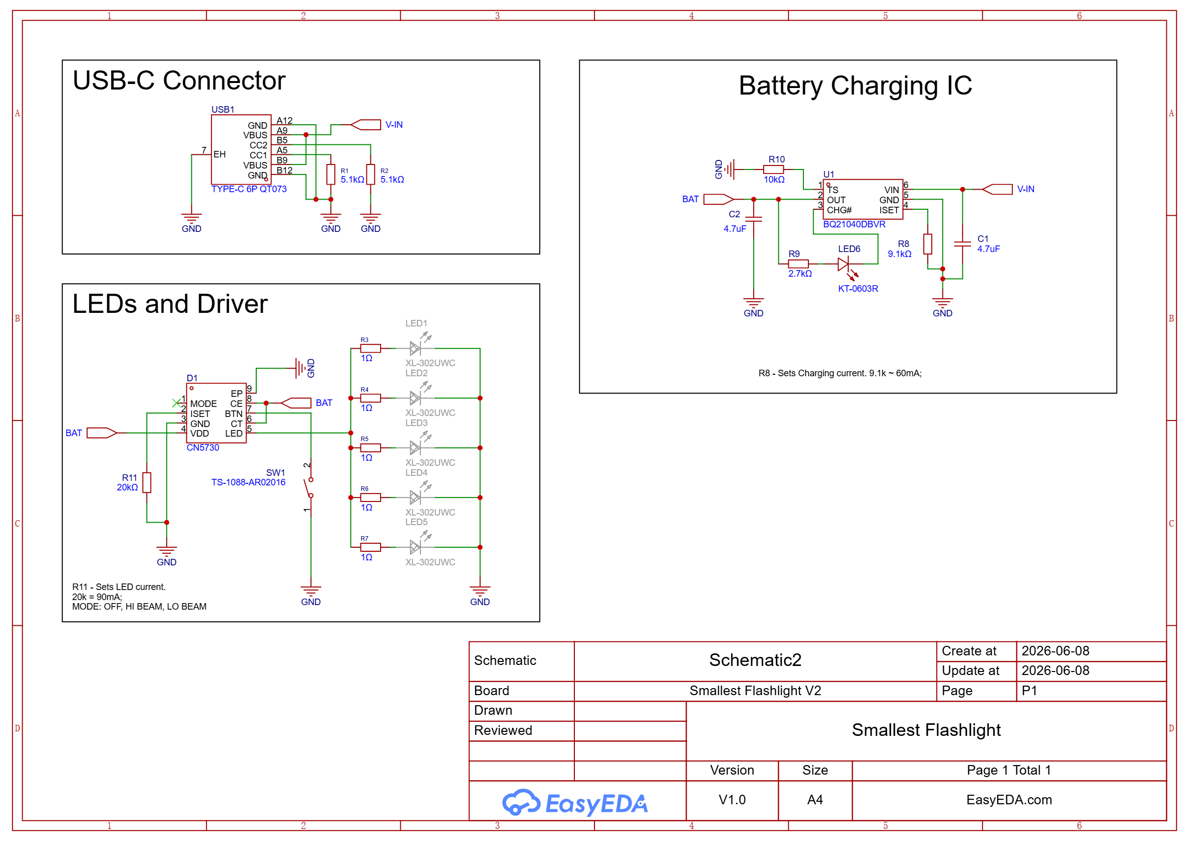
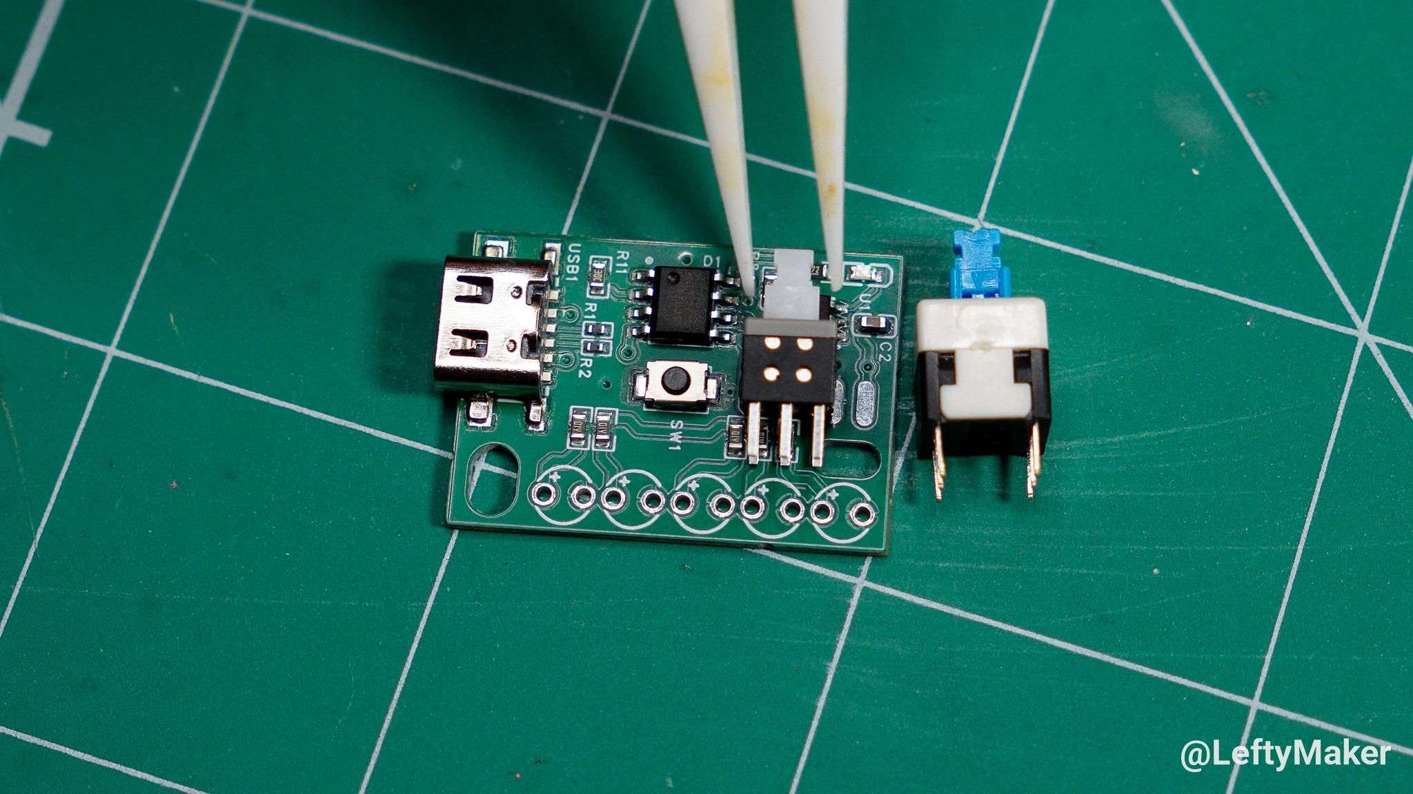
Before I go over the circuit board design, I should explain the circuit itself. I've split it in three main sections for clarity: the USB port, the charging circuit, and the LED driver.
🔌USB-C port (LCSC Part Number C2681548) – I picked this particular USB port for my design for several reasons. It doesn't have any legs sticking through the PCB and it is cheap since it uses six pins only (2x GND, 2x Voltage, and CC1 and CC2 pins). I must mention that two 5.1k resistors are connected from each of the CC pins to ground. This allows the circuit to function with smart chargers and Type-C to Type-C cables.
🔋Battery charger: Texas Instruments BQ21040 (LCSC Part Number C202311) – Power from the USB port goes to the battery charging chip. The BQ21040 is a small, linear battery charging integrated circuit that requires only a few external parts to work and supports low currents. I have it configured for 60mA – the current setting depends on the value of the resistor between pin 4 (ISET) and GND. Although the chip can be adjusted to up to 800mA of charging current, smaller batteries charge at lower currents for safety. A single LED indicates when the battery is charging. When it is full, chip automatically stops pushing current to the battery, and the LED turns off.
💡LED driver: Consonance CN5730 (LSCC Part Number C840502). Power from the battery goes to the LED driver. This is a special component designed to push a constant current to one or several LEDs, regardless of the input voltage – I have an in-depth LED driver explanation video on my YouTube channel.
There are several benefits of using this LED driver as opposed to resistors in series with the LEDs. First of all, it is possible to achieve greater efficiency. Secondly, the LED brightness remains constant no matter the battery's charge level. But most importantly, this particular chip offers several features ideal for this project:
- It can be turned on and off with a simple push button. Even the smallest switch buttons are considerably bigger than momentary ones due to the mechanical parts that make them work.
- I supports several brightness levels: you can cycle between high-brightness, low brightness, flashing, and off. The flashing function can be disabled.
However, there is also a notable downside: the LED driver consumes a bit of power when in stand-by. It is in the microamp range, but it is enough to drain the battery in about four months.
Although this LED driver is made for high-power LEDs and can handle over 1A of current, I have it configured to operate at 90mA – each of the five LEDs gets about 18mA. The 1-ohm resistors in series with each of the LEDs are not mandatory, but they ensure that the current will be distributed evenly among the LEDs.
The Circuit Board
.png)
.png)
.png)
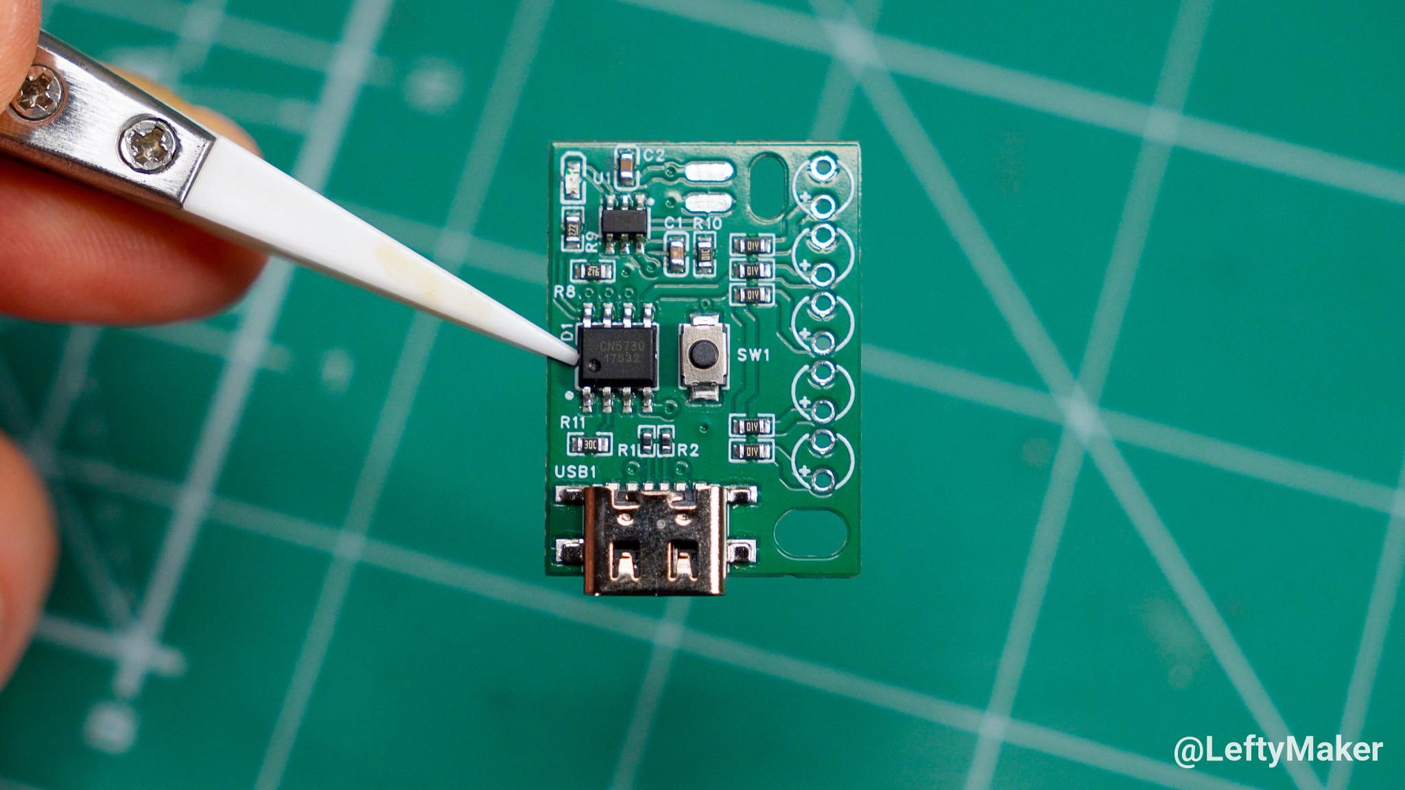
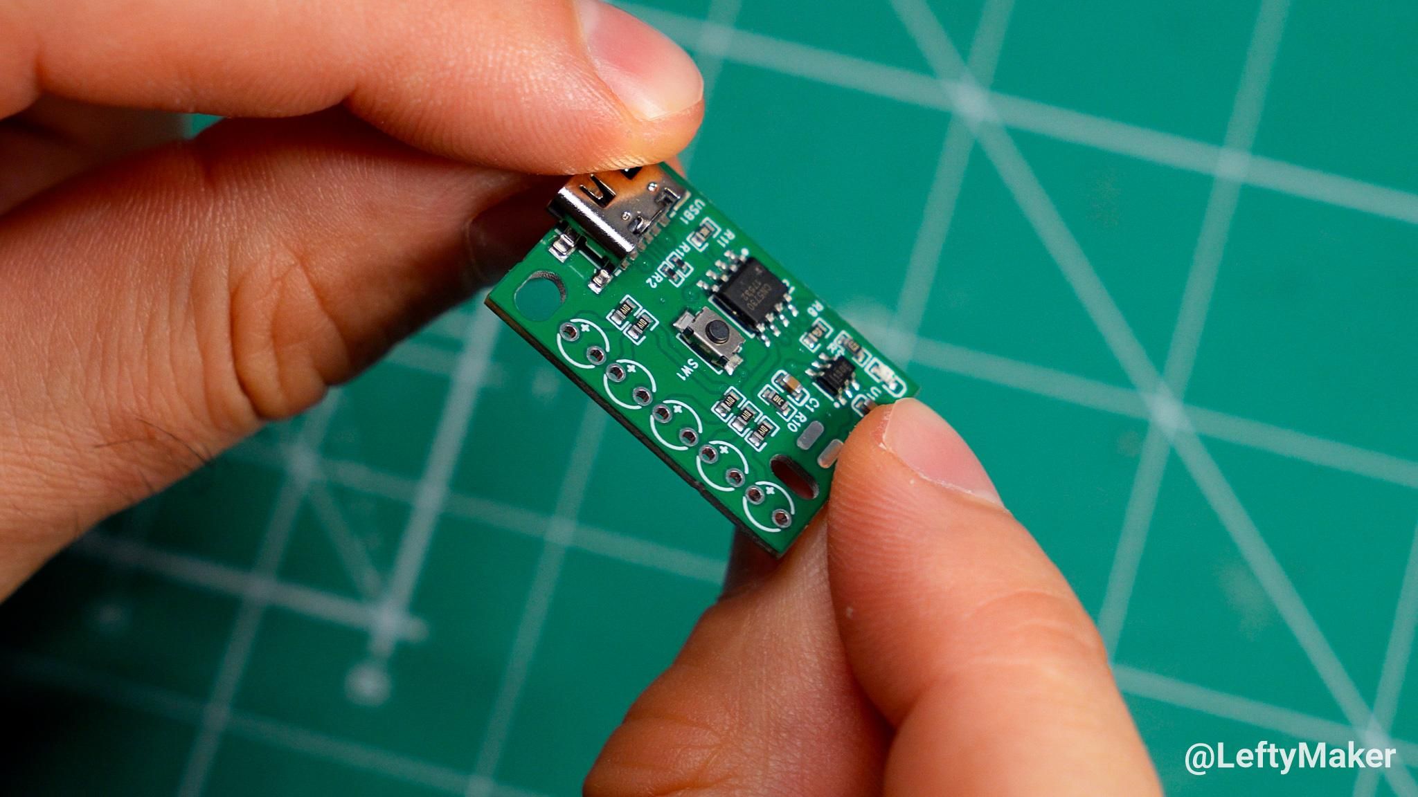
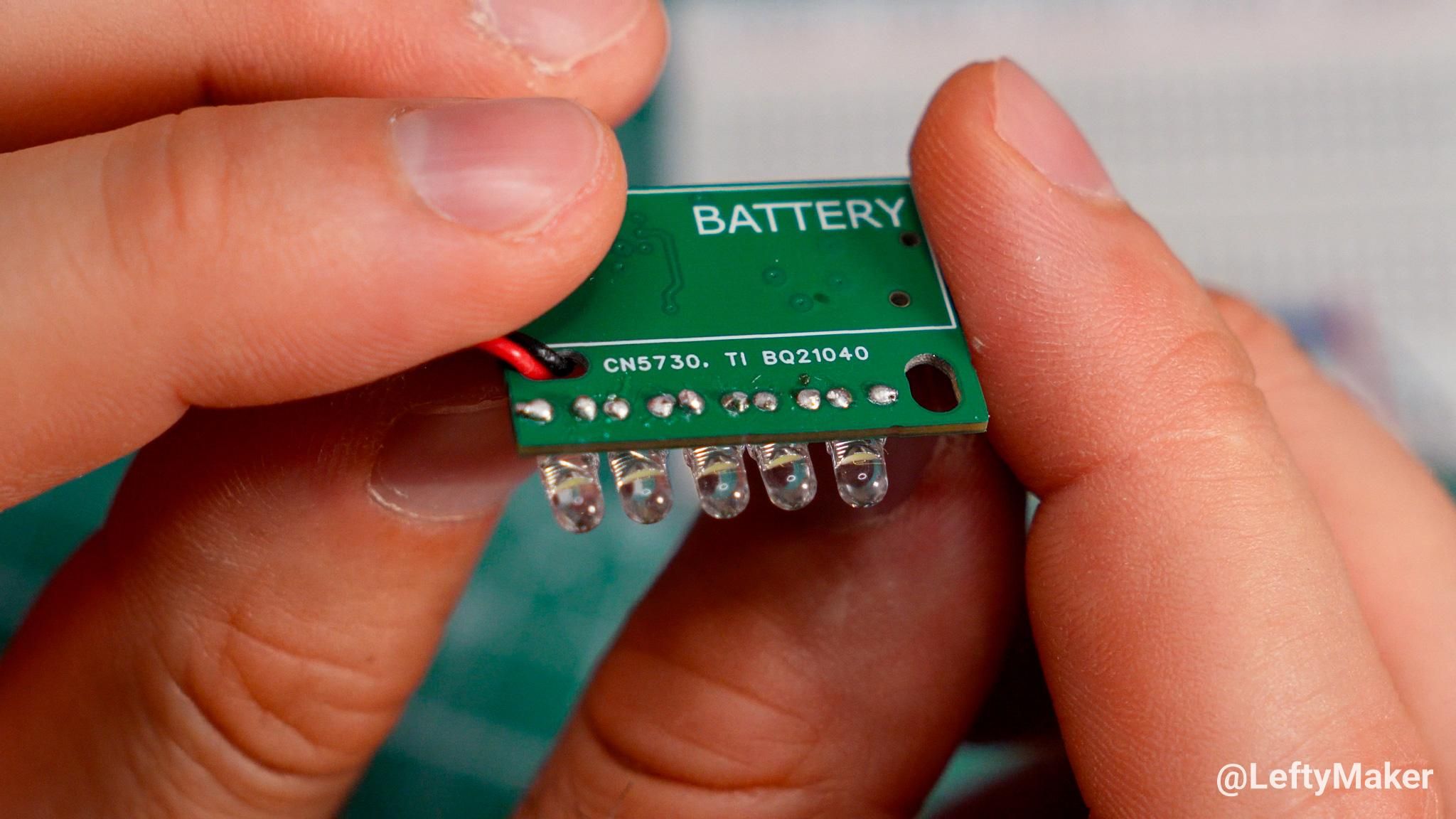
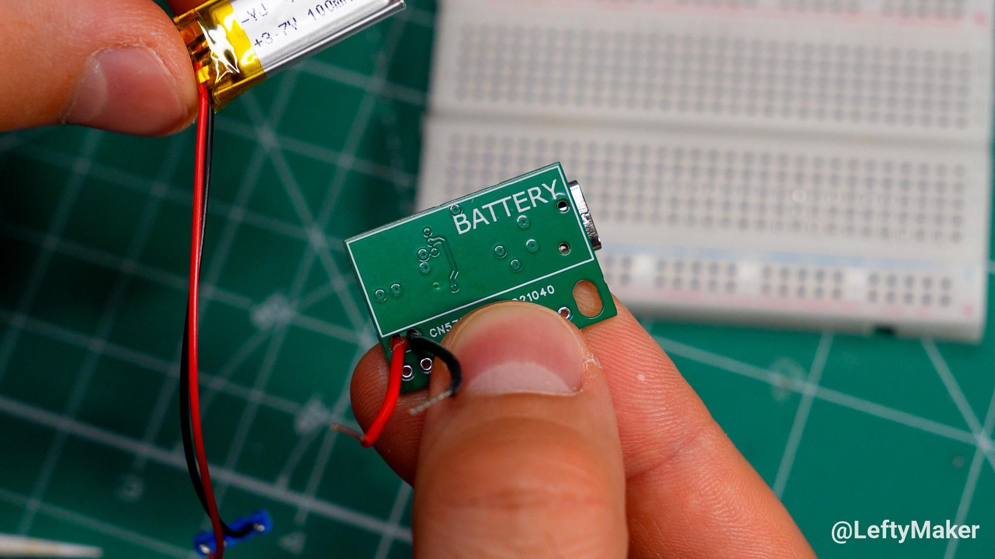
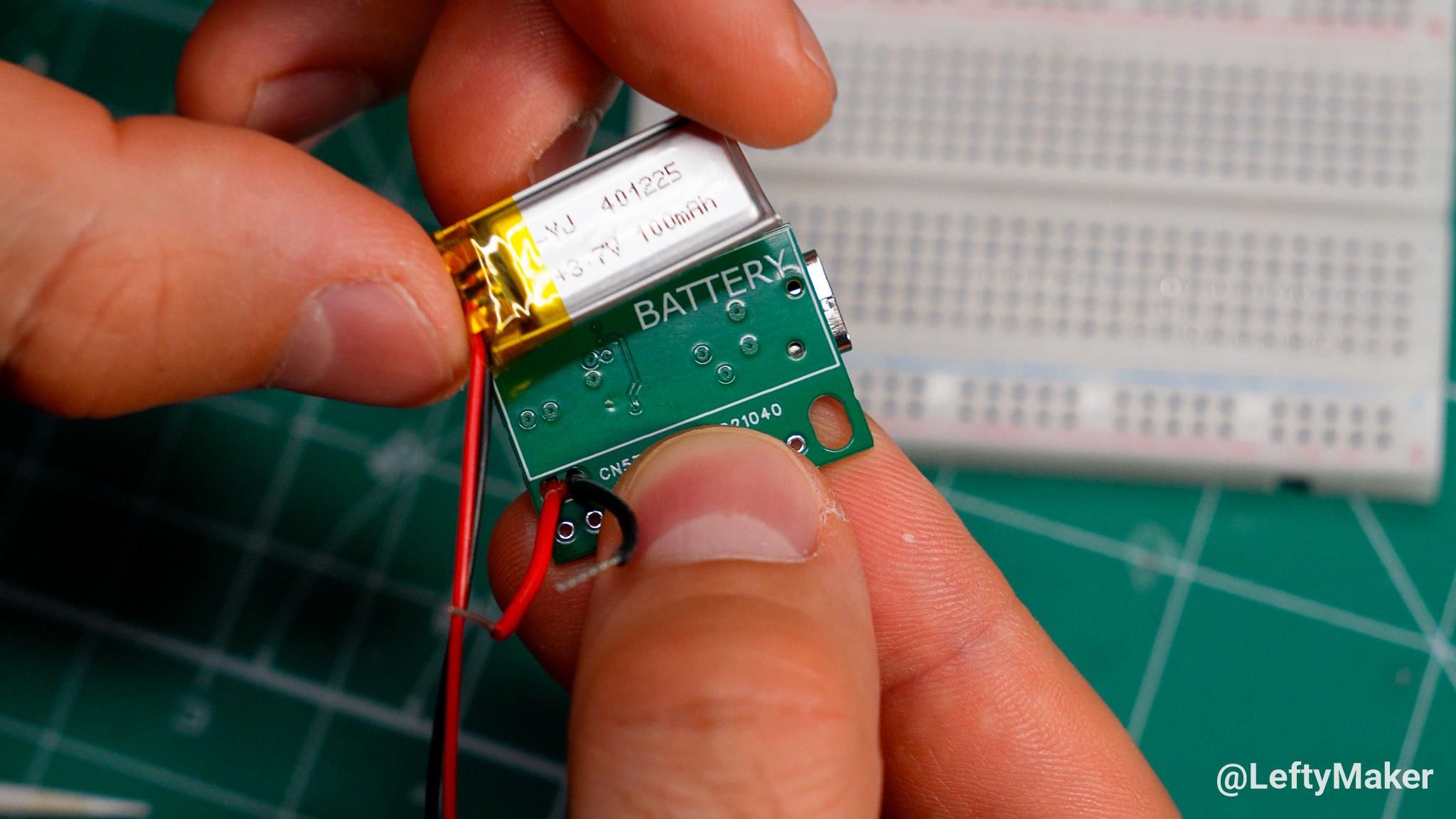
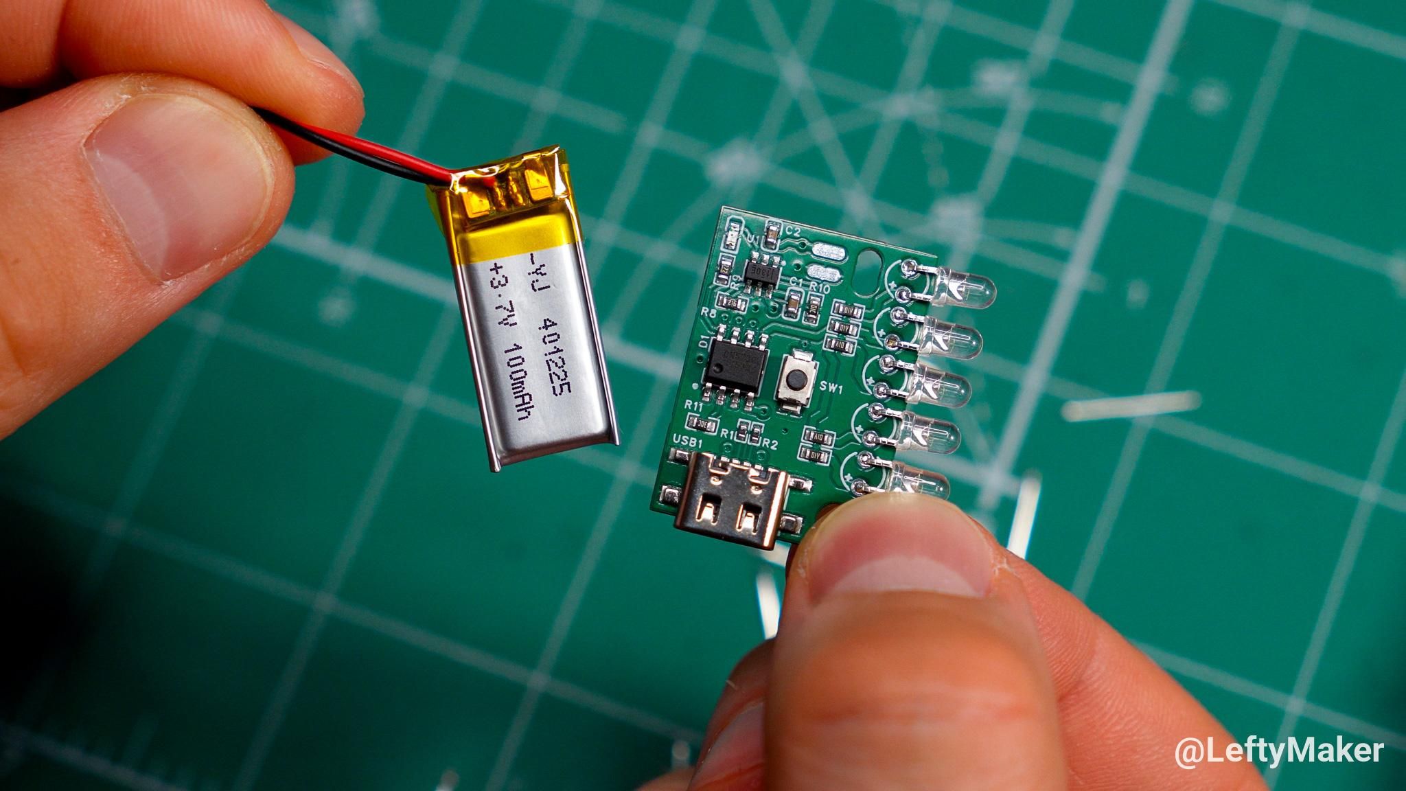
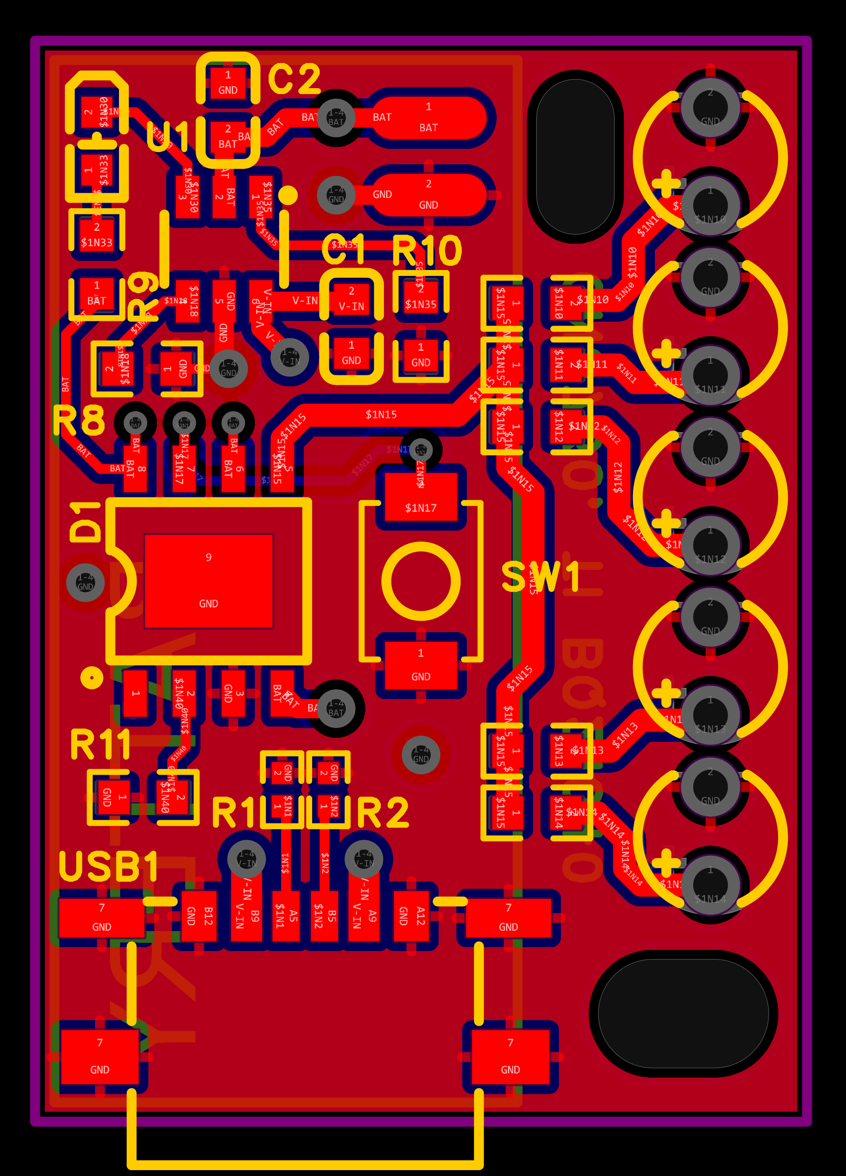
A project like my tiny flashlight greatly benefits from a custom circuit board. It allows me to fit all the essential components (USB port, LED driver, battery charger) onto a single, tightly packed PCB instead of using separate pre-made modules for each.
Besides, the chips, capacitors, and resistors used throughout are surface-mount components. SMD parts – designed to be soldered onto pads on the surface of a circuit board – are much smaller than their through-hole alternatives. The only components I had to solder myself were the five LEDs, which all go in their dedicated spots on the side, and the battery, for which I have two dedicated voltage and ground pads.
There are two openings in the PCB. The one next to the battery charging chip is for the battery wires to go through. The one in the corner was originally intended for alignment only, but eventually, I decided to use it for an M3 screw to hold the two pieces of the enclosure together.
I ordered this circuit board from JLCPCB, whose services I've been using for years, but I expect the project files to work with other PCB manufacturing companies. The PCB has four layers, and I ordered mine with a thickness of 1mm. The SMD parts were soldered professionally by JLCPCB.
⚠️ Warning: the legs of through-hole components can damage a battery if it is pressed against them. That is why the battery goes underneath the section of the PCB with SMD parts only. The location is marked on the bottom side of the PCB.
The 3D-printed Enclosure
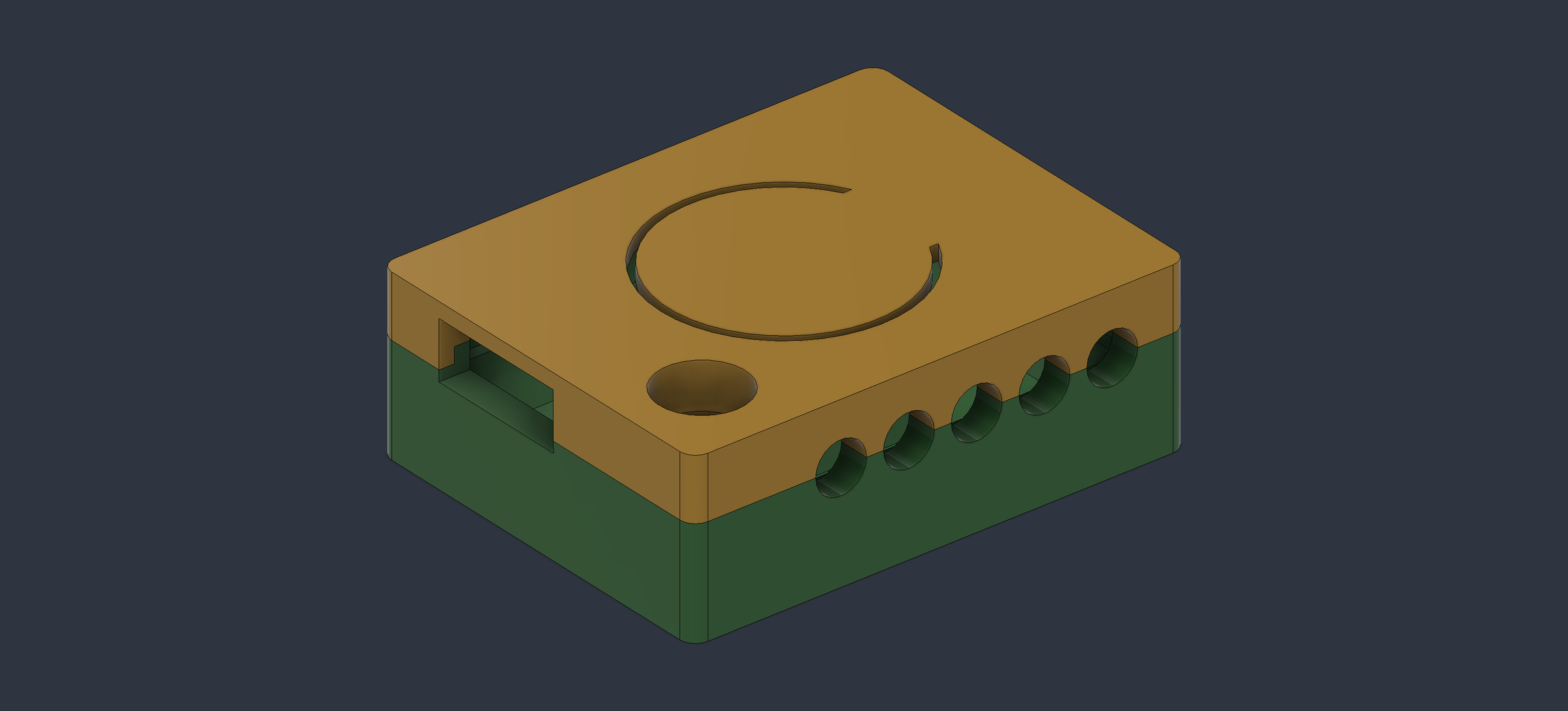
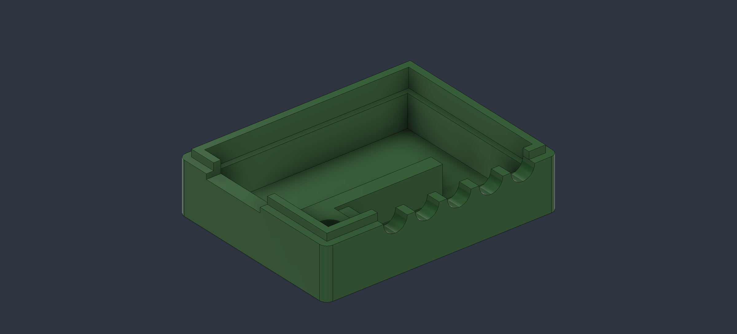
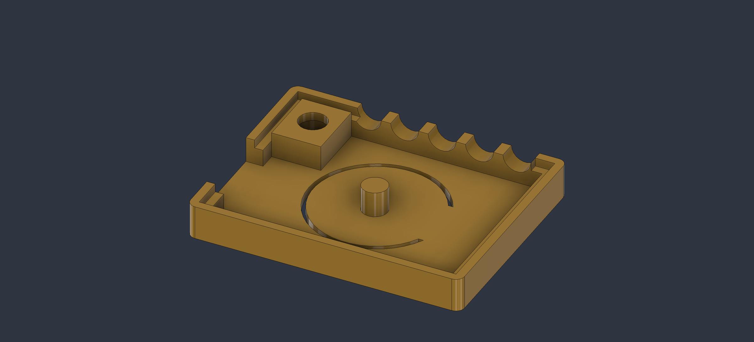
I wouldn't call myself a 3D-printing and design expert, and I'm confident the enclosure could have been designed better. I went through several iteration until I ended up with one that worked well enough.
My enclosure is made of two parts: the bottom has a section where the battery fits, and the top is designed with a flat, bendy section which pushes the power button when pressed. The two pieces fit together with a slot and a ridge going around the perimeter. The fit ended up not being super tight, so I added the openings for the screw and the nut. There are openings on the sides for the USB port and for the LEDs.
Downloads
It's DONE!
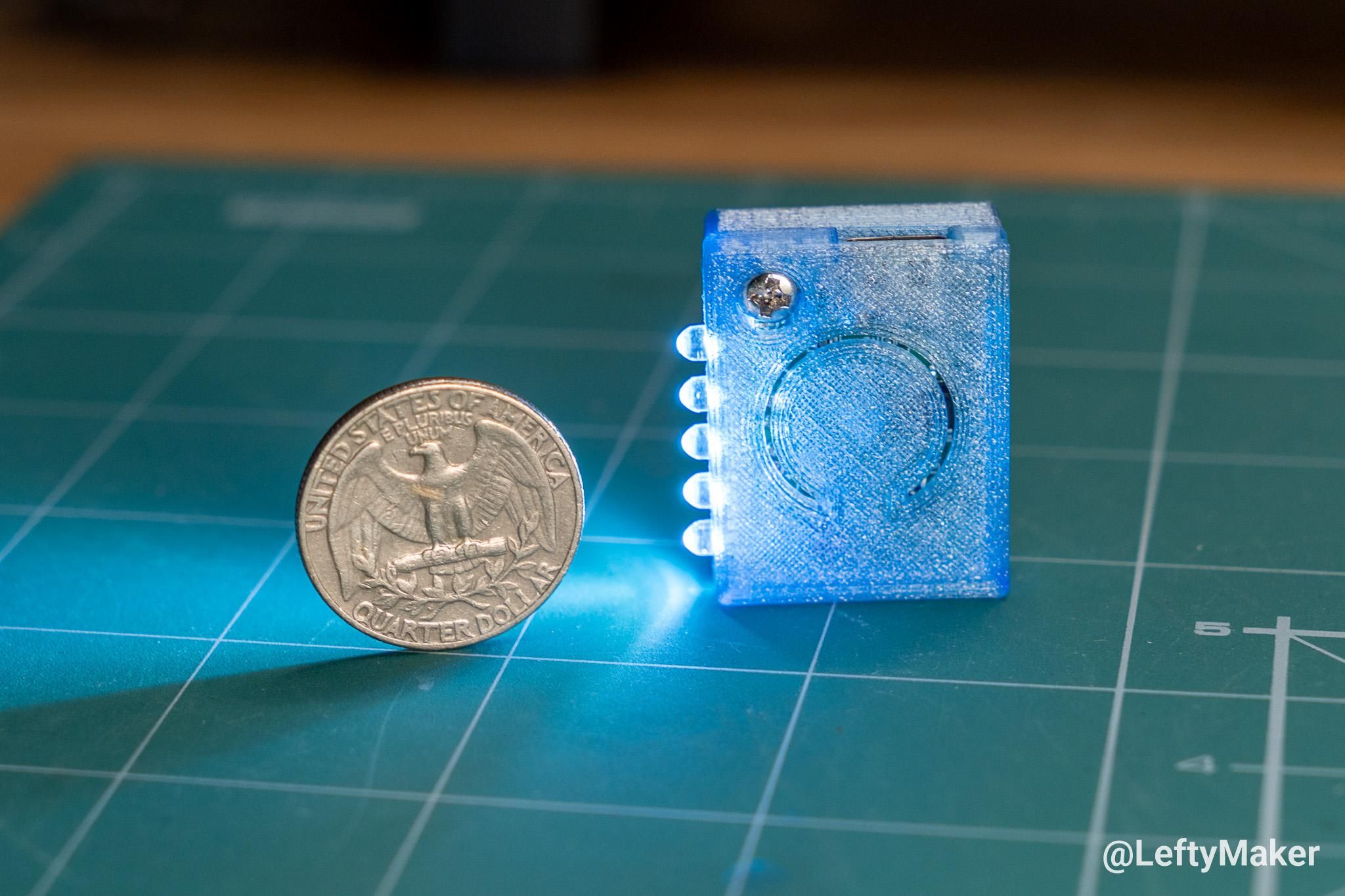
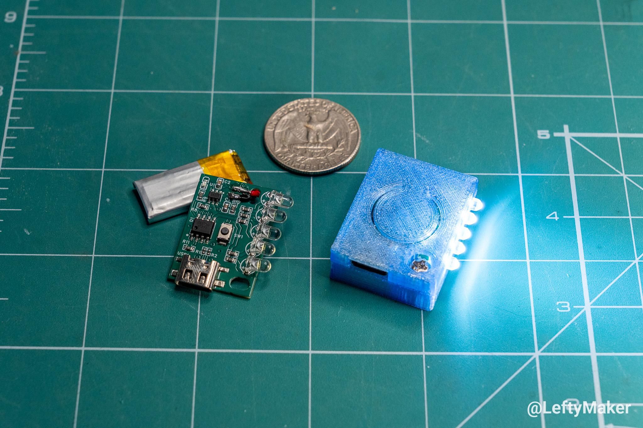
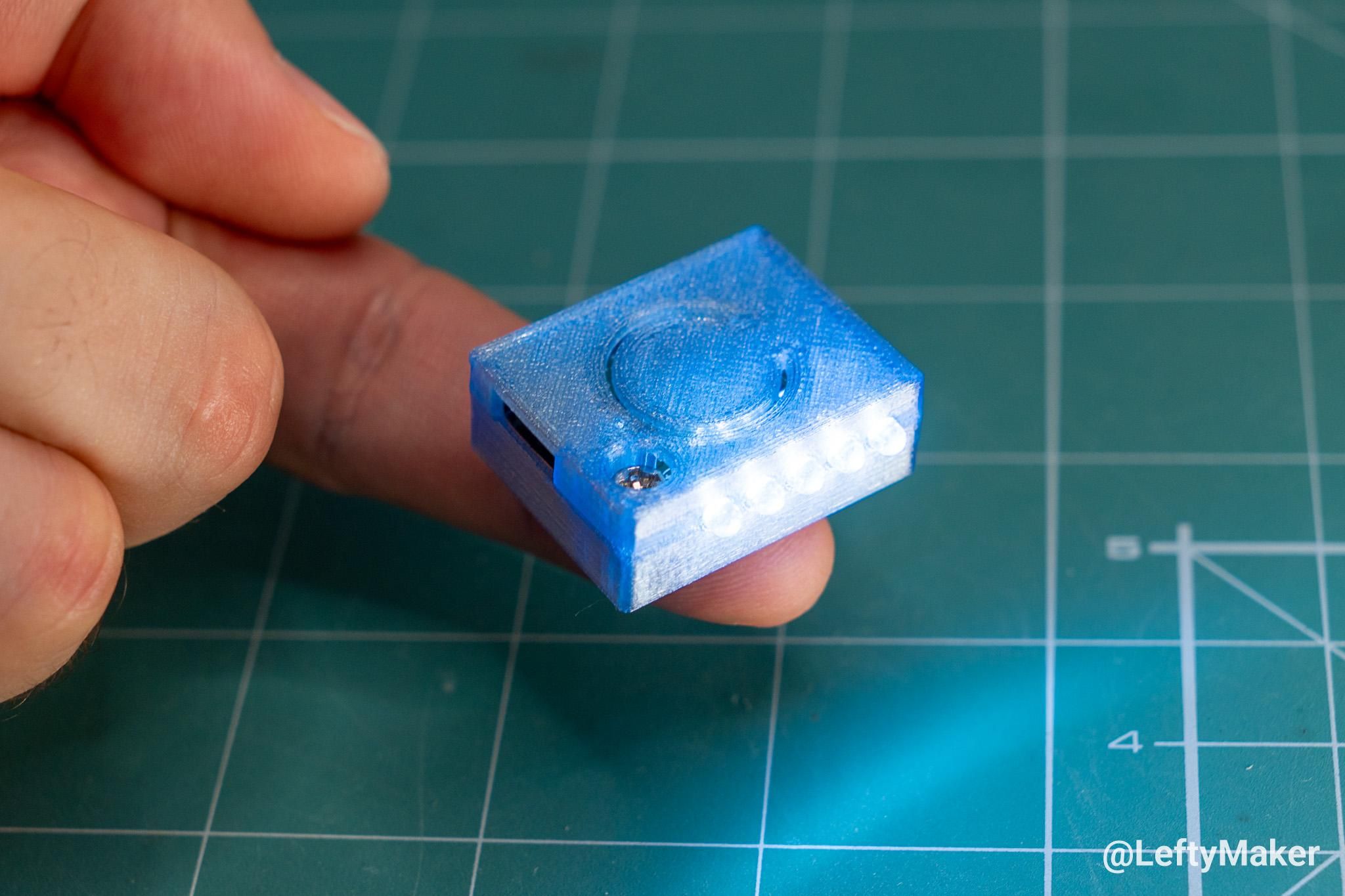
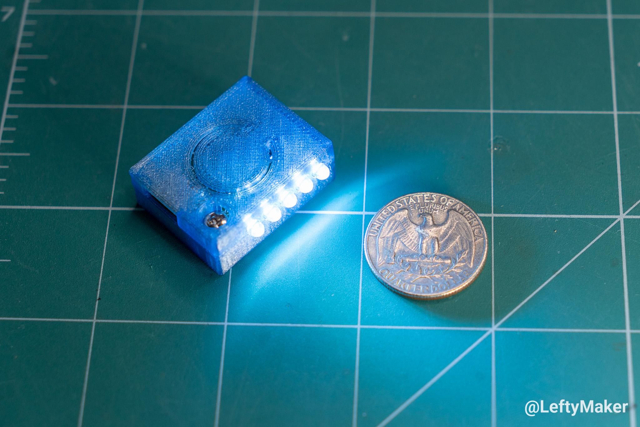
As mentioned earlier, my flashlight design isn't as small as the one that inspired it. It ended up being around three times bigger. However, it is still small enough to fit into any pocket, and with a tweak to the enclosure design, it would make a cool keychain.
In terms of battery life, I measured 54 minutes at high brightness. At low brightness, I got 2 hours and 29 minutes out of a single charge.
As for light output, the flashlight at high brightness looks as bright as my phone's camera LED light at a medium setting. In other words, it is perfectly usable.