Tobi-P, the Robotic Rabbit Companion
by jdelbe in Circuits > Robots
2098 Views, 17 Favorites, 0 Comments
Tobi-P, the Robotic Rabbit Companion


Tobi-P ("Pi-bot" read backwards) is a fully open-source companion, bringing smiles and good mood at home.
The nose is a tilt camera, making it a FPV robot controllable from the dedicated Android app.
The body has been entirely designed with Blender, and requires no screw to assemble.
It is white on the outside, orange on the inside.
Supplies
- Pololu DRV8835 Dual Motor Driver Carrier
- Pololu 100:1 Micro Metal Gearmotors HP 6V
- Pololu Micro Metal Gearmotor Brackets
- Pololu Wheels 32×7mm
- Pololu Ball Caster + 3/4″ Metal Ball
- Raspberry Pi 1 Model B rev 2 (512MB)
- Raspberry Pi Camera Module v2.1 + ribbon cable
- Power Bank with dual output (2,1A + 2,4A)
- Wifi Nano USB Adaptor
- SD card (at least 8GB recommended)
- Micro servomotor 4.8/6V
- USB A connector plug kit
- Micro-USB cable (very short)
- Wires
- Iron wire
- Googly eyes
- Fabric for the ears
- Wool ball for the tail
- PETG filament (white, orange)
Check Your Raspberry Pi Revision

The heart of Tobi-P is a Raspberry Pi 1 Model B (512 MB), which is now obsolete. Recent versions of the board should work well as replacements though.
In particular the Raspberry Pi Zero W should be good enough, it even has wireless already. However some of the following steps may need to be adapted, as well as some of the requirements and components (camera cable, Ethernet, board power requirement, footprint in the case...).
Customize Your Future Companion

Because Tobi-P already exists and is unique, you should change some of its features if you decide to build one. ;)
It could be a different color, or longer ears for instance. Having different relatives is cool! :)
Also don't forget to pick up a name for your new companion!
Prepare the SD Card
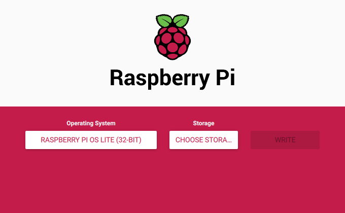

Let's start with the brain part of our project: the software.
-
Download and install the latest Raspberry Pi Imager from the official website.
-
Insert the SD card into your computer, or connect a SD card reader with it inside.
-
Launch the program, select Raspberry Pi OS (other) -> Raspberry Pi OS Lite (32-bit)
-
Choose your SD card in the "Storage" tab.
-
Press Ctrl-Shift-X to open the advanced options.
-
Set the hostname to tobi.
-
Enable SSH and choose a password.
-
Click "Save", then "Write", and wait for the download and copy to finish.
Note:
If using Raspberry Pi Imager on Windows 10 with controlled folder access enabled, you will need to explicitly allow Raspberry Pi Imager permission to write the SD card. If this is not done, the imaging process will fail with a "failed to write" error.
Setup the Raspberry Pi
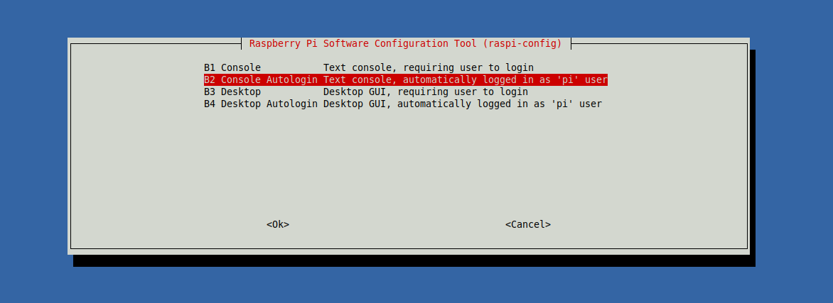
- Insert the SD card in the Pi and connect an Ethernet cable.
- Power it up. No need to use the power bank yet, a standard USB charger 5V @ 2A is enough.
- SSH into it.
- Start the raspi-config utility to change some of the default settings:
sudo raspi-config
1 System Options -> S5 Boot / Auto Login -> B2 Console Autologin
3 Interface Options -> P1 Camera -> Yes
4 Performance Options -> P1 Overclock -> High
                      -> P2 GPU Memory -> 16 MB
5 Localisation Options -> L2 Timezone -> Select yours
                       -> L4 WLAN Country -> Select yours
6 Advanced Options -> A1 Expand Filesystem -> Ok
- Finish and reboot to apply the changes:
sudo reboot
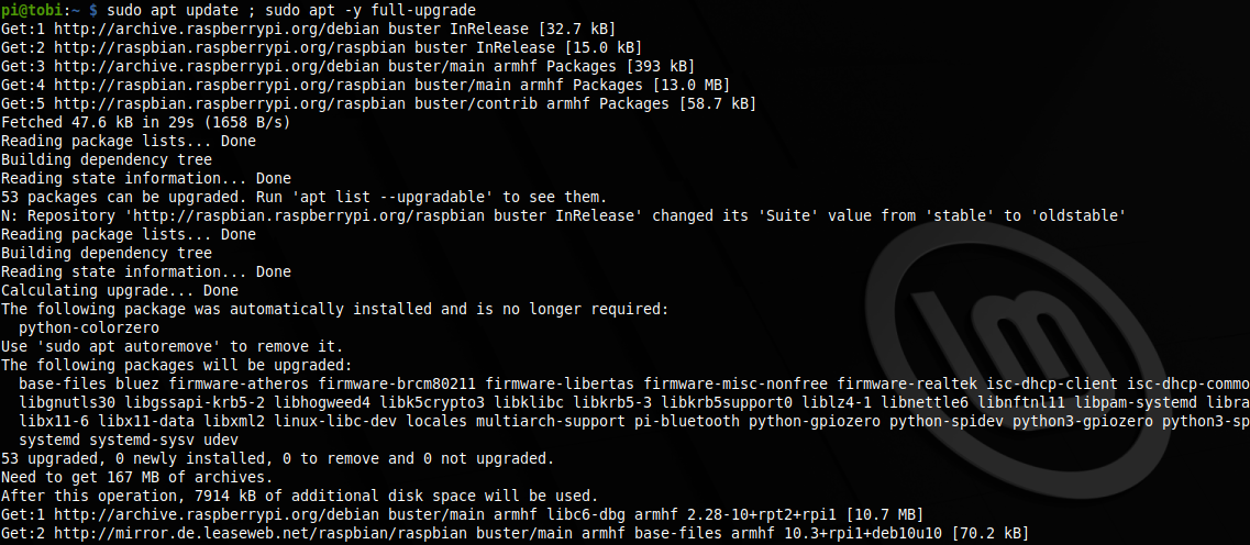
Optionally, it would be a good time to update the OS:
sudo apt update ; sudo apt full-upgrade
sudo reboot
Install the Software


If not already present, install git:
sudo apt install git
Then get the latest version of the robot software stack:
git clone https://gitlab.com/jdelbe/tobi-p.git ~/tobi_catkin_ws/src/tobi-p
Now simply start the installation script which will take care of everything:
cd ~/tobi_catkin_ws/src/tobi-p/tobi_bringup/scripts
./install.bash
Note: the last step can be VERY long, as it installs ROS and everything from sources!
As long as the spinner keeps spinning though, everything is fine :)
Be patient, or start already with the next step.
Once the installation is successful, run the last to command to shut down the Raspberry Pi:
sudo poweroff
You can now unplug the power (micro-USB) and the LAN cables.
Prepare the Motors


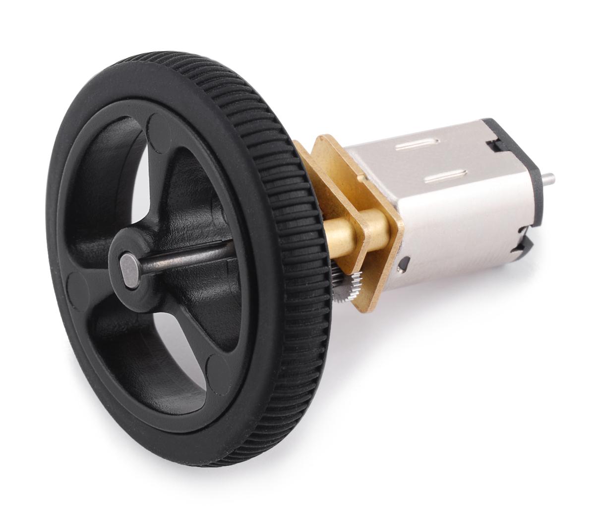
We now start to give Tobi-P its ability to move.
First, solder 2 wires (preferably of different colors), to the brushed motors. Since the motors are identical, we will keep the same +/- convention for both.
This is optional, but I really like using standard 2.54mm Dupont connectors (with crimping pliers) to manage wires.
Once this is done, you can already fit the wheels and tires.
Prepare the Motor Driver


Solder the provided headers, it is way more convenient than soldering cables directly onto the little board.
Both orientations are possible, just keep in mind that you will want to be able to read the labels on the PCB later, when this is full of wires.
Prepare the USB Connector

Carefully follow the pin configuration of a USB Type-A connector and solder the red wire on the Vcc (+5V) pin, the black wire on the Ground pin. This will be responsible for providing power to the previous board.
Once soldered, put the different pieces of the plug kit together. Depending on the one you have, it can be a pain to fit everything into the plastic casing.
Here I have used again 2.54mm connectors for the other end of the red and black cables.
Wire Up the Electronics

Follow the above diagram to connect :
- the motor driver to the Raspberry Pi GPIOs
- the motors to the motor driver
- the USB connector (from the previous step), between the motor driver and the power bank (2.4A output)
- the micro servomotor to the Raspberry Pi GPIOs
- the short micro-USB cable to the Raspberry Pi (power input port)
It is in theory fairly simple, but it is easy to make mistakes as well. The wiring of the motor driver in particular can get a bit tricky. The DRV8835 product page has all the details and further explanations, should you want them.
For the Raspberry Pi, the pinout website is also a good reference.
Connect the Remaining Components

- If your Raspberry Pi has no native wireless capability, plug the USB Wi-Fi adapter.
- Insert the ribbon cable for the camera into the Raspberry Pi camera module, then correctly connect the other end of the ribbon cable to the Raspberry Pi.
- Finally plug the remaining end of the short micro-USB cable to the power bank (2.1A output)
With the last step, the Pi should power up.
Download and Install the Android App


We want to to test if everything is functioning, especially after the last 2 steps.
For this we need an Android device and the control application: the latest release version is available for download from the dedicated project repository, for convenience.
Note:
You should never install a program if you don't trust its origin!!
Feel free to build the apk directly from the sources, that is the beauty of open source!
Then simply install the application.
Connect to the Access Point and Start the App

- Turn on the Wi-Fi on your Android device.
- Display the list of available Wi-Fi networks.
- Select Tobi-AP, our Access Point.
- Type the password, the default is "Tobi-Pass-42".
Once connected to the robot network, launch the ROS Control app for the first time. Allow it to access media, location and camera.
Configure the App for Your Robot

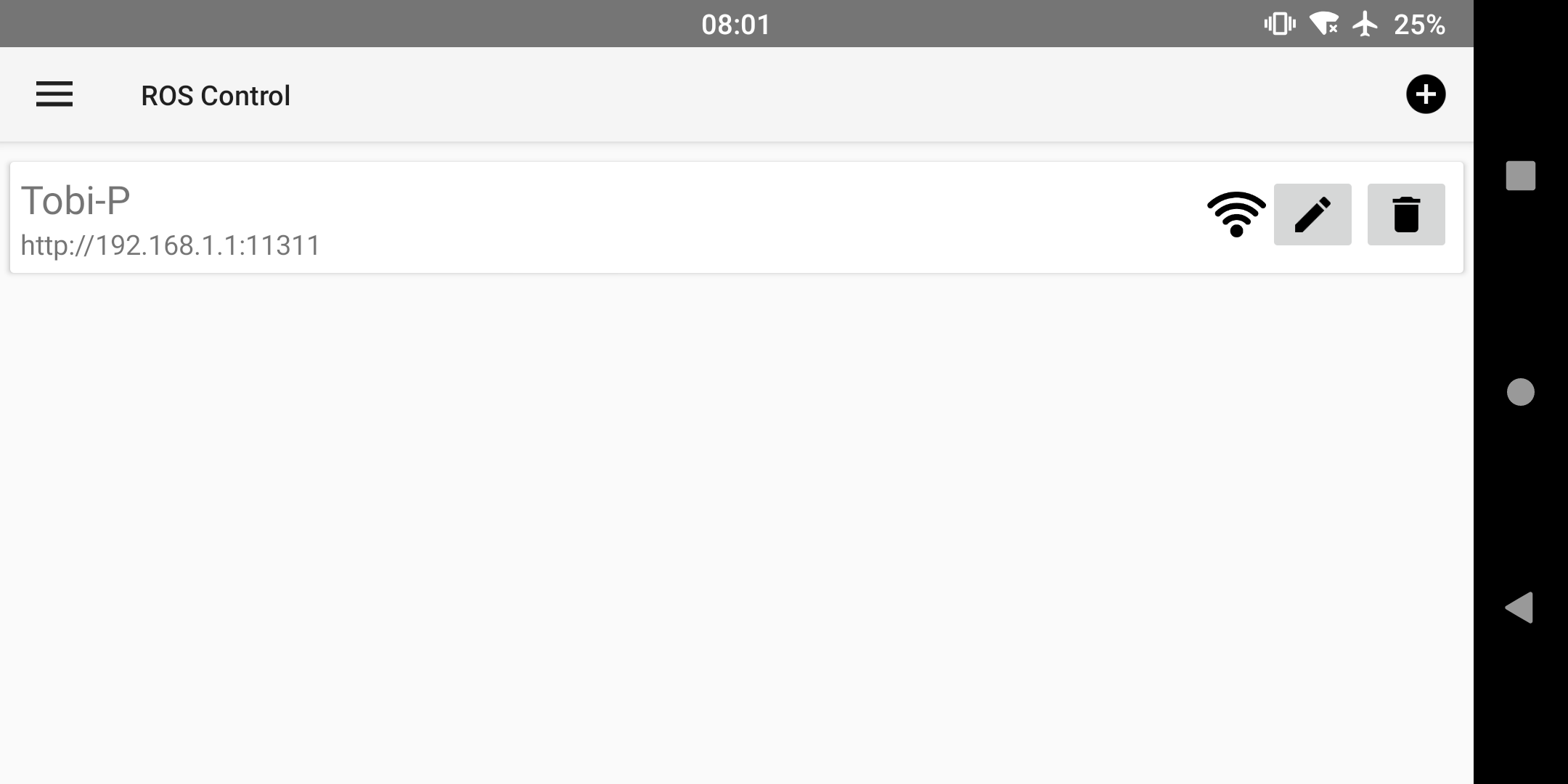
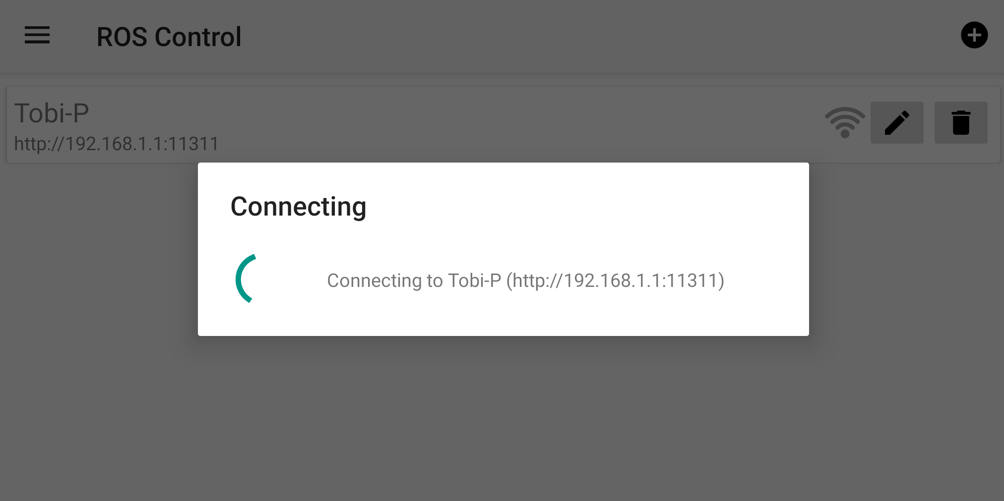
Follow the instructions on the screen to add a new robot:
- Give it a name
- set the Master URI to: http://192.168.1.1:11311
The signal icon should turn black if the robot is detected. Click on it to connect, the application should now switch to the main window.
Check That Everything Is Working

From the main screen, try now to move the slider up and down. It should rotate the servo.
Move the joystick in all directions, and check that the orientation of both wheels is the one expected.
Try moving the camera a bit, to make sure that the image is not frozen.
Note:
When the app is started for the first time, it can take take several seconds before everything works normally. This is specially true for the camera.
Congratulations, the core of your new robot is working!
You can unplug the power bank as well as most of the components. The next time we connect them will be for the complete assembly.
Download the 3D Files

It is now time to give our new companion its body.
Go to the dedicated project page and download all the files. The page also has all the information and detailed settings for 3D printing.
Adapt the Parts to Your Case

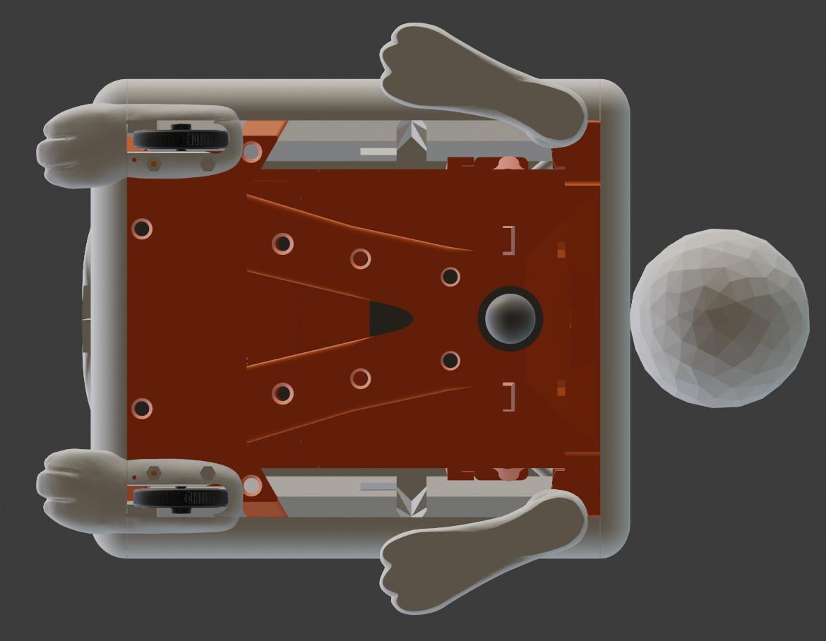

As mentioned in the first step, some adjustments may be needed if you are using a different Raspberry Pi than mine. This concerns particularly the Raspi_Plateau, which is tailored for my revision (screw holes, connector orientation...).
It is anyway a good idea to check all the parts with your favorite CAD software before taking the next steps.
Slice the Parts for Your 3D Printer


In my case I'm using the latest version of PrusaSlicer (2.3.3 at the time of writing).
Be sure to refer to the details on the project page in the previous step, for instance regarding the non-manifold meshes.
As a rule of thumb, I have used a resolution of 0.20mm most of the time, except for the parts with smooth edges on the external cover.
Turning on the variable layer height feature is also advised, as it really optimize the quality/time ratio.
3D Print the Case


Start with the orange parts (inner structure), since they will not be visible in the end.
This way you still have means to edit the next pieces and correct the printing settings, should anything from the 2 previous steps not go as planed.
When printing the white parts (outside case), start from the back pieces for the same reason.
The panels for instance only need to have a nice and flat surface, the rest is hidden. But this is the first layer, so make your printer is correctly tuned for that.
Make the Fluffy Parts

The big pom pom for the tail can easily be made by hand, whereas a smaller one can be created with a fork.
The ears are made of different fabric stitched together. The white one is made of 2 layers, creating an opening for an optional iron wire. The iron wire gives some stiffness to the ears and allow them to bend nicely to your will.
Ready the Face Accessories

We are getting closer to our goal, our companion is slowly gaining its personality!
- Run some very important functional tests on the googly eyes.
- Check that the camera is fitting nicely into the nose hole.
- Make sure the muzzle looks awesome when put on the face.
- Cut a few pieces of iron wire (about 2 cm long) for the whiskers.
Prepare the Assembly

First verify that the 3D printed parts all fit correctly together: here is a video for the orange parts, and here one for the white parts.
Gather and line up all the pieces for the big next step, as well as a few tools: a screwdriver, pliers, and maybe some glue.
Assemble Everything

Follow the video for the complete assembly!
Take your time, pause or slow down the video for the sections where you need it.
It is a quite long process, but the result is definitely worth it!
Power Up Your Robot, and Enjoy!


Congratulations !
You have finished creating your new companion, and it is now ready to be guided from your pocket device.
I hope it will bring you joy and entertainment, as much as Tobi-P does in our home!
Also don't hesitate to share your creations on the website! :)